

patent · EP0235896A1
Electromagnetic flow coupler for regulating flow rate/pressure
9 September 1987
Text
Page 1bibliographic recordscan →
J » European Patent Office 5i) Publication number: 0 235 8 9 6
Office europgen des brevets
EUROPEAN PATENT A P P L I C A T I O N
Application number: 87300519.3 intci- H 02 K 44/00, G 21 C 1 5 / 2 4
Date of filing: 21.01.87
Priority: 24.01.86 US 822183 Applicant: WESTINGHOUSE ELECTRIC CORPORATION, Westinghouse Building Gateway Center, Pittsburgh
Pennsylvania 15235 (US)
Inventor: Alexion, Christopher Constantine, 14320 Michael Drive, North
Date of publication of application: 09.09.87 Huntingdon.Pennsylvania 15642 (US) Bulletin 87/37 Inventor: Nathenson, Richard David, 5301 Fair Oaks Street, Pittsburgh, PA 15217 (US)
Inventor: Keeton, Alvin Robert, 5055 Don Street,
Finleyville, PA 15332 (US)
Representative: van Berlyn, Ronald Gilbert, 23, Centre
Designated Contracting States: BE DE FR GB NL Heights, London, NWS 6JG (GB)
Electromagnetic flow coupler for regulating flow rate/pressure. A flow characteristic regulating electromagnetic flow ■32a. coupler (10) is disclosed as comprising a pump duct (36) and a generator duct (38) for connection in separate flow circuits containing electrically conductive fluid. Circuit means (26) electrically connect the separate fluid in each of the pump and generator ducts (36, for conducting electric current through the fluid in each of the pump and generator ducts (36, transversely of the fluid flow therethrough. Means are provided for applying respectively first ^ and second magnetic fields (42, through the fluids of the ^^< generator and pump ducts (38, transversely of the current and fluid flow therethrough, whereby the fluid driven the duct (38) forces the fluid to flow
(O through the generator *q through
JjJ pump duct (36). Means are provided for setting W the magnetic flux density of the first and second magnetic (0 fields (42, in the generator and pump ducts (38, at different levels B1 and B2 respectively, whereby the flow char- S4fe acteristic of the forced fluid in the pump duct (36) is greater
O than that flow characteristic of the drive fluid in the generate tor duct (38).
III
ACTORUMAG
Page 2scan →
Electromagnetic flow coupler
For regulating flow r a t e / p r e s s u r e
This invention relates to electromagnetic (EM) flow couplers and, in particular, to such couplers as adapted for regulating the flow rate or the pressure of the driven flow of a metal fluid.
5 As is well known in the art, EM p u m p s produce a pressure differential or a pressure head between the inlet and the outlet through the interaction of an electrical current and a crossed magnetic field. This interaction produces an electromagnetic force throughout the volume of 10 the fluid within the pump region wherever both the current density and the magnetic field are non-zero. At each such point, this force is dependent on not only the magnitude of the current density and magnetic flux density vectors, but also on their relative orientation. The maximum force 15 density and resulting pressure differential occurs when the current and the magnetic field are mutually perpendicular to each other and to the direction of fluid flow. There are two basic types of EM p u m p s . A first type known as an AC (alternating current) pump includes 20 means for applying an alternating magnetic field to the liquid metal. In an AC EM pump, the alternating magnetic field induces a corresponding AC c u r r e n t through the liquid metal, whereby a force is exerted thereon. In a DC EM pump, a steady state electromagnetic field and a steady 25 state or DC current are applied to the liquid metal, whereby a corresponding force is exerted thereon.
Page 3scan →
Typically, DC EM pumps are constructed in a rectangular duct by mounting two electrodes flush with the opposite side walls of the duct and placing the other two electrically conductive walls between magnetic pole faces. 5 When the two electrodes are connected to an external power supply, current flows across the duct and interacts with the magnetic field to produce a directed EM force and pressure difference along the duct. The pump's inlet and exit regions are defined roughly by the electrode edges. 10 These regions may vary somewhat depending upon the relative location of the magnetic pole face edges. In an ideal pump, all the current would be confined to the duct volume enclosed by the electrodes and the pole faces, where the force density is the greatest. In an actual pump, however, 15 some current leaks into the. magnetic fringe region both upstream and downstream from the electrode edges. This
DC EM p u m p s , in small sizes up to several horsepower, have been used for many years in liquid metal cooled 20 reactors where extremely high reliability of the has pump been required. Large DC EM p u m p s having several thousand horsepower have not been used in reactor systems for two main reasons: (1) inability to obtain suitable high ' current/low voltage power supplies, and (2) problems of 25 transmitting the high current from the power supply to the pump without high resistance losses. Suitable high current/low voltage power supplies are now available which may take the form of a Faraday disc generator producing high current at relatively low voltages as would be suit- 30 able to drive DC EM p u m p s . However, current transmission problems associated with such current generators require the use of large current buses. To overcome both of these problems, two ducts may be arranged side-by- side in a common magnetic field with one such duct acting as an EM 35 generator and the other acting as an EM pump. This arrangement of EM p u m p s is commonly referred to as a "flow coupler" and is described in U.S. Patent No. 2,715,190 of
Page 4scan →
Brill and U.K. Patent No. 745,460 of Pulley. Brill, however, had both the generator and pump duct constructed to the same dimensions and had a uniform magnetic field extending across both ducts. Thus, the flow rate and 5 pressure difference were the same for both ducts. In a typical flow coupler, a liquid metal is caused to flow through a generator duct. Passage of the fluid through the common magnetic field generates a large current in the generator duct which is transferred to a 10 pump duct by short, low resistance electrodes. Interaction of the current in the pump duct with the common magnetic field produces a driven flow in the pump duct. In this manner, the flow of a first liquid metal in the generator duct is "coupled" to the flow of a second liquid metal in 15 the pump duct. The local generation of the current enables lower voltages and higher currents to be used than would be possible with an external power supply. The lower voltages, in turn, reduce end current losses and permit higher overall efficiencies, on the order of 60%, to be attained. 20 Early in the development of the liquid-metal fast breeder reactor (LMFBR), it was recognized that liquid metals could be pumped by the EM p u m p s as described above. Such EM p u m p s and flow couplers offer significant advantages in the reactor environment due to their inherent 25 simplicity and lack of moving parts. In "Sodium Electrotechnology at the Risley Nuclear Power Development Laboratories," by D. F. Davidson et al., NUCLEAR ENERGY, 1981, Vol. 20, February, No. 1, pp. 79-90, there is discussed the use of EM pumps and flow couplers in LMFBR systems. EM 30 flow couplers serve to transfer hydraulic power from one liquid metal flow circuit to another. Each circuit is isolated from the other so that there is no mixing of the
A flow coupler typically has a pump duct and a 35 generator duct of equal sizes, the ducts coupled in each circuit and disposed side-by-side between the poles of a 5 permanent magnet. The pump and generator ducts are electrically connected by the low resistance electrodes so that a current induced by flow in one duct passes through the other duct to produce a driving pressure. The side-by-side 5 arrangement of the two ducts is disposed between two magnetic poles, whereby an equal magnetic flux is induced in each duct. For ducts of equal size in equal magnetic fields, it has been found impossible to make the flow rate through the pump duct greater than that of the flow rate 10 through the generator duct. Such a limitation is a disadvantage in those reactor designs requiring higher flow rates in the pump duct than in the generator duct. The Pulley patent, noted above, discloses a flow coupler wherein a pressure transformation may be achieved 15 between two ducts in inverse ratio to the duct depths. In this arrangement, equal flux density is maintained in the two ducts. Further, Pulley discloses that the flow velocity may be transformed in direct proportion to the duct widths. Where the pressure drops in the two ducts are kept 20 equal, a low flow rate may be established through a secondary or pump duct of large cross-section to provide a high flow rate in the pump duct of small cross-section. An examination of the Pulley patent indicates that the magnetic flux in each of the ducts of such a coupler remains 25 equal and that flow pressure or flow rate may be changed as a function of the dimensions of the ducts. Pulley, however, does not extend to the anti-parallel flow cases, a situation made necessary by requiring the magnetic field to be the same across both ducts.
30 A principle object of the invention is to provide an improved EM f l o w coupler in which either the flow rate or the pressure of the driven flow may be varied.
Accordingly, with this object in view, the present invention resides in a flow characteristic regu- 35 lating electromagnetic flow coupler comprising:
Page 6scan →
a) at least a first pump duct and at least a first generator duct for connection in separate flow circuits containing electrically conductive fluid; and b) circuit means for electrically connecting the 5 separate fluid in each of said first pump and first generator ducts and for conducting electric current through the fluid in each of said first pump and first generator ducts transversely of the fluid flow therethrough; characterized
10 c) means for applying respectively first and second magnetic fields through the fluid of said first pump and said first generator ducts transversely of the current and fluid flow therethrough, whereby the fluid driven through said first generator duct forces the fluid to flow 15 through said first pump duct; and d) means for setting the flux density of the first and second magnetic fields in said first generator and said first pump ducts at different levels Bl and B2, respectively, whereby the flow characteristic of the forced 20 fluid in said first pump duct is greater than that flow characteristic of the driven fluid in said first generator duct.
The preferred embodiment of the invention will be described, by way of example, with reference to the accom-
Figure 1 is a broken away, perspective view of a regulating EM f l o w coupler in accordance with the teachings of this invention;
Figure 2 is a broken away, perspective view of a 30 further embodiment of this invention in which a second pump duct is associated with the generator duct;
Figure 3 is a schematic diagram of the equivalent, electrical circuit of the regulating flow coupler of this invention acting as a flow/pressure amplifier;
35 Figure 4 is a graph illustrating the efficiency versus the ratio of flow rates through the ducts of an EM 7 flow coupler for the case of equal flux densities in each duct;
Figure 5 is a graph illustrating the efficiency as a function of the ratios of flow rates in each of the 5 ducts of a flow coupler where each duct is of the same height;
Figure 6 is a curve indicating the efficiency as a function of the ratio of pressures where equal flux densities are established in the ducts of a flow coupler; 10 Figure 7 is a curve of the efficiency as a function of the ratio of the pressures where the ducts of a flow coupler have equal duct heights; and
Figure 8 is a side, sectioned view of a parallel flow coupler wherein the fluid flows in the pump and 15 generator ducts are in the same direction.
Referring now to the drawings and in particular to Figure 1, there is shown a regulating electromagnetic (EM) flow coupler, which is referred to generally by the number 10 and comprises a pump duct 36 and a generator duct 20 38 disposed in a side-by-side relationship. The regulating EM f l o w coupler 10 includes a side wall 14, a top wall 16, and a bottom wall 18 forming in conjunction with an electrically conductive divider plate 26, the pump duct 36. In a similar fashion, the regulating EM flow coupler 10 25 includes a top wall 20, a bottom wall 22, and a side wall 24 defining in conjunction with the electrically conductive divider plate 26, the generator duct 38. The walls 14, 16, 18, 20, 22 and 24 are made of a highly electrically conductive material such as copper. The electrically conduct- 30 ive divider plate 26 may be made of a copper alloy. The divider plate 26 functions as a circuit means for electrically connecting the pump duct 36 and the generator duct 38, whereby a current is permitted to flow in both ducts transversely to the fluid flow therethrough. Further, 35 layers or sheets 28 and 30 of insulating material are respectively disposed on the topmost and lowermost surfaces of the ducts 36 and 38. Such sheets 28 and 30 may be made 8 of a suitable insulating material such as alumina, where relatively high temperatures are contemplated, or a glass epoxy, where relatively low temperatures are expected. As explained above, a current is generated within the generat- 5 or duct 38 as directed along a current path 48 as seen in Figure 1. The side wall 24 acts as an electrode, while the top walls 16 and 20 act as a return conductor to permit current flow along a return current path 50a. In a similar fashion, the bottom walls 18 and 22 act as a return con- 10 ductor to establish a second return current path 50b. The return current paths 50a and 50b are coupled to the side wall 14, which acts as an electrode to direct the current along the current path 48 through the liquid flowing in the pump duct 36, the divider plate 26 and the liquid flowing 15 in the generator duct 38.
As indicated above, the EM f l o w coupler 10 may be particularly adapted for use in a liquid-metal fast breeder reactor, wherein reactive liquid metals such as sodium are circulated. In such applications, an inner, protective 20 duct 52 may be disposed within the pump duct 36. The inner, protective duct 52 may be formed of a relatively thin, approximately 40 to 60 mil thickness, layer of a relatively high resistance conductive material such as stainless steel manufactured under the designations 304 and 25 316 or Inconel number 718. The inner protective duct 52 is formed on the inner surfaces of the side wall 14, the insulator sheets 28 and 30, and the divider plate 26. A similar inner, protective duct 54 may be disposed within the generator duct 38, as shown in Figure 1.
30 A first set of magnetic poles 32a and 32b is aligned such that their axes are disposed vertically, as shown in Figure 1, so that the magnetic field 40 generated thereby is likewise disposed in a vertical orientation to pass through the pump duct 36. In a similar fashion, 35 there is provided a second set of magnetic poles 34, whose axes are aligned vertically, as shown in Figure 1, so that their magnetic field 42 is directed vertically to pass 9 through the generator duct 38. As is well known in the art, the first and second sets of magnetic poles 32 and 34 may be either permanent magnets or electromagnets. As illustrated in Figure 1, the air gap A formed between the 5 first set of magnetic poles 32a and 32b is made greater than the air gap B between the second set of poles 34a and 34b. As a result, the strength of the magnetic field Bl established between the second set of poles 34a and 34b is greater than the magnetic field B2 established between the 10 first set of poles 32a and 32b.
The regulating EM f l o w coupler 10 of this invention is capable of operating as a flow characteristic amplifier, wherein the flow characteristic may be either the flow rate or the pressure rise of the metal fluid along 15 the duct. In the flow rate amplifier mode of operation, the duct height t2 of the pump duct 36, i.e., that dimension along the direction of the magnetic field as indicated by the arrows 40 in Figure 1, is made greater in the pump duct 36 than the corresponding dimension tl in the gen- 20 erator duct 38. Further, the magnetic flux density Bl is made greater in the generator duct 38 than the flux density B2 in the pump duct 36. As shown in Figure 1, the air gap established between the magnetic poles 32a and 32b is greater than the air gap established between the magnetic 25 poles 34a and 34b, whereby the magnetic field Bl established within the generator duct 38 is greater than the magnetic field B2 established within the pump duct 36. Thus, by varying one or both of the duct heights tl and t2 and the magnetic flux densities Bl and B2, high- 30 efficiency operation may be achieved in which the flow rate within the pump duct 36 is greater than the flow rate through the generator duct 38.
In a second mode of operation, the regulating EM flow coupler 10 may be operated as a pressure amplifier, 35 whereby the pressure rise of the fluid within the pump duct 14 is made greater than the pressure drop of the fluid within the generator duct 38. In particular, the duct
Page 10scan →
^ 0 235 8 9 6 height tl of the generator duct 38 is made greater than the duct height t2 of the pump duct 36, or the flux density B2 within the pump duct 36 is made greater than the flux density Bl within the generator duct 38.
5 These design considerations required for operating the regulating EM f l o w coupler 10 as a pressure amplifier are exactly opposite to the design considerations for operating the coupler as a flow rate amplifier. It is impossible to have both flow and pressure amplification in 10 the same design. To achieve pressure amplification, the ratio
15 must be made greater than unity in order that the pressure ratio is greater than unity. Conversely, to achieve slow rate amplification, the ratio
20 ( W must be greater than unity for the flow rate ratio to be
A simple analysis of the flow coupler was presented in the above-referenced Pulley patent assuming 25 one-dimensional magnetic field, current and flow and no 'fringing of current or field outside of the center region of the EM flow coupler. The equations for flow rate and pressure drop through the generator duct can be written in 11 where Bl is the magnetic flux density in generator, tl is the duct height, II is the duct current, El is the voltage developed across the generator duct, API is the pressure drop along the generator duct 38, and 01 is the flow rate of the metal circulated through the generator duct 38. Similarly, the equations for flow rate and pressure rise through the pump duct 36 can be written:
10 Here, the subscript 2 refers to the parameters relating to
Figure 3 is an electrical, equivalent circuit of the distributed system comprising the generator duct 38, the pump duct 36, and the bus bar or electrically conduct- 15 ive divider plate 26 disposed therebetween. The electrical elements as indicated in Figure 3 are defined as follows: Rl is the ohmic resistance of the fluid directed through the generator duct 38 within the magnetic field Bl. R2 is the ohmic resistance of the fluid directed through the pump 20 duct 36 within the magnetic field B2. Re is the total resistance in the paths 48 and 50 from the generator duct 38 to the pump duct 36 , which includes the ohmic resistances of the divider plate 26 and the walls 14, 16, 18, 20, 22 ,. and 24, and the interfacial resistance presented 25 between the liquid metal and the exposed surfaces of those inner ducts 52 and 54 overlaying the side walls 14 and 24 and the divider plate 26. The relationship between the 12 ii 0 235 8 9 6 currents and voltages presented in the generator duct 38 and the pump duct 36 is expressed as follows:
The relationship between the flow rate Ql and the 5 pressure drop API of the liquid metal circulated through the generator duct 38 and the flow rate Q2 and pressure rise AP2 of the liquid metal pumped through the pump duct
36 is derived by rearranging equations (1) and (2) to obtain expressions for II and El and 12 and E2 , which are 10 substituted into equation (3). Subsequent matrix conversion and multiplication of equation (3) provides:
Ap. ap
"Rl + R2 + V B2/t:J j |__ i 2 J. L _ _
Such an EM f l o w coupler 10, wherein the liquid metals flow in opposite directions as indicated by arrows 46 and 47, is
15 known as an anti-parallel flow coupler.
Page 13scan →
The second equation of the matrix expression (4) can be divided by Ql and the following expression of the ratio of the flow rates obtained:
The opposite signs are provided on Ql and Q2 as a matter of mathematical notation to indicate power flow out of a duct as positive and power flow into a duct as negative. It is clear, then, that (t2/tl) must be made sufficiently greater than the reciprocal of the bracketed term of expression (5) in order" to ensure that the flow ratio is greater than one to achieve flow amplification. Qualitatively speaking, the pump duct height t2, as shown in Figure 1, must be sufficiently greater than the generator duct height tl and/or the pump flux density B2 must be sufficiently less than the generator flux density
The expression for pressure ratio can also be derived :
AP2 B2/t2 AP (B2/Bl)
L APl I W
I r 1 •
(B2/B1} mUSt be made sufficiently greater than unity in order to make the ratio of the pressures differentials greater than unity to achieve pressure amplification. This is evidence that the flow ratio and pressure ratio are inversely proportional to one another.
The expression for hydraulic efficiency^ of the flow coupler 10 is defined as the flow power output of the 14 pump duct 36 over the flow power input to the generator
11 = * ' (7)
with the minus sign included to make ti p o s i t i v e . Substituting the relationship (6) between API and AP2 into equa-
( h ( h (^> (8)
Thus, the efficiency n increases indefinitely as the flow ratio increases. However, this simple theory neglects end effects which, upon increased pump flow rate, 15 would cause generator action to start in the pump duct 36. This would lower the net pressure rise in the pump duct 36 and, thus, the efficiency ti . Thus, the efficiency n must reach a maximum for some value of the flow ratio. Numerical and analytical studies as reported in 20 "A Quasi-One-Dimensional Analysis of an Electromagnetic Pump Including End Effects", in Liquid Metal Flows and Magne t o h y d r o d y n a m i c s , Progress in Astronautics and Aeronautics, Vol. 84, AIAA, New York, 1983, by W. F. Hughes and I. R. McNab, have led to the development of a 25 quasi-one-dimensional analysis of the DC EM pump that includes end effects. This theory was extended to the DC EM g e n e r a t o r and, eventually, to the EM f l o w coupler in a report, "High Efficiency DC Electromagnetic Pumps and Flow Couplers for Pool-Type LMFBRs", in Liquid Metal Flows and
Page 15scan →
Magnetohydrodynamics, Progress in Astronautics and Aeronautics, Vol. 84, AIAA, New York, 1983, by I.R. McNab and C.C. Ale:-:ion. Later, in experimental studies described in "Demonstration of Flow Couplers for the LMFBR" , December 5 1983 by EPRI , R.D. Nathenson-, et al., it was shown that the flow coupler theory accurately described the operation of a prototype flow coupler of the type shown in Figure 1. The quasi-one-dimensional analysis of the flow coupler will now be described for the case of a flow or 10 pressure amplifier. Sample curves of efficiency n as a function of flow rate 0 have been generated for the sake of comparison. Figure 4 shows how the height ratio (the generator duct tl height over the pump duct height t2 ) affects the efficiency ti for the case of equal flux den- 15 sities in the two ducts. It can be seen that increasing the height ratio increases the optimum flow ratio value, that is, the point where maximum efficiency is reached. It also has an overall effect of slightly decreasing the maximum efficiency ti . Figure 5 shows how the flux density 20 ratio (B2/B1) affects the flow amplifier efficiency n for the case of equal duct heights, tl=t2 . I t c a n be s e e n t h a t decreasing the flux density ratio increases' the optimum flow ratio value, and it also increases the maximum effi-
25 The case of the pressure, amplifier is presented graphically in Figures 6 and 7. The effect of height ratio t2/tl is shown in Figure 6, where the flux densities Bl and B2 have been equalized for clarity. It clearly shows that pressure amplification is only accomplished for (t2/tl<l. 30 The effect of flux density ratio is shown in Figure 7.
Here, the height ratio was fixed at unity for simplicity. Overall, the efficiency n increases slightly as the flux density ratio is increased, as shown in Figure 7. Referring now to Figure 2, there is shown a 35 further embodiment of this invention, where elements similar to those in Figure 1 are identified by similar numbers except numbered in the hundred series. Figure 2 16 illustrates a regulating EM coupler 110 having more than one pump duct. In particular, the flow coupler 110 has a second flow duct 137 that is separated from a generator duct 138 by an electrically conductive divider plate 127. 5 In addition, a magnetic field 133 is established by a third set of magnetic poles 135a and 135b that direct a magnetic flux in a vertical direction as indicated by arrows 143. In a further embodiment of this invention, it is contemplated that there would be two generator ducts 10 and a single pump duct. In the embodiment as shown in Figure 2, it is contemplated that the metal fluids as driven through the pump ducts 136 and 137 are isolated from each other and may be different metals as driven along the paths indicted by the arrows 147 and 144, 15 respectfully. Though not shown in Figure 2, inner ducts may be disposed within each of the generator ducts 138 and the pump ducts 13 6 and 137 to protect against the corrosive attack of such metal liquids as sodium.
Referring now to Figure 8, there is shown a 20 further embodiment of this invention, where elements similar to those in Figure 1 are identified by similar numbers except numbered in the 200 series. In particular, Figure 8 shows a parallel flow coupler 210 wherein the liquid metals in the pump duct 23 6 and the generator duct 25 238 flow in the same direction as indicated by the x's 246 and 244, i.e., into the page as seen in Figure 8. The construction of the parallel flow coupler 210 differs from those of the embodiments of Figures 1 and 2 in that the parallel flow coupler 210 is comprised of a first U-shaped 30 electrode 219 and a second U-shaped electrode 217. The generator duct 238 is formed by portions of the first and second electrodes 219 and 217 and, in particular, by the side wall 224 and the bottom wall 222 of the first electrode 219 and a side wall 215 of the second electrode 35 217. Insulating members 228 and 230 are disposed parallel to each other and extend from the side member 224 to the side member 215. In a similar fashion, the pump duct 236 17 is formed by the side wall 214 and the top wall 216 of the second electrode 217 and the side wall 223 of the first electrode 219. Insulating members 231 and 227 extend parallel to each other from the side wall 223 to the side wall 214. A first magnetic field Bl as indicated by arrows 240 is directed through the pump duct 236. A second magnetic field B2 as indicated by the arrows 242 is directed through the generator duct 238, whereby a current is directed through the liquid flowing therethrough along a path indicated by the arrow 248a. The first U-shaped electrode 219 provides a return path as indicated by the arrow 250a to the pump duct 236, wherein the current flows across a path indicated by the numeral 248b. Similarly, the second U-shaped electrode 217 provides a return path 250b for the current to flow from the pump duct 236 to the generator duct 238. As seen in Figure 8, the current flows in opposite directions along the paths 248a and 248b f w h e r e a s the liquid flows w i t h i n the generator duct 238 a n d t h e pump d u c t 236 in t h e same direction. The flux densities Bl and B2, as well as the heights of the generator duct 238 and the pump duct 236, may be varied as explained above whereby the flow characteristics such as flow rate or pressure within the pump duct 236 may be controlled.
Page 18scan →
Claims
1. A flow characteristic regulating electromagnetic flow coupler (10) comprising:
(a) at least a first pump duct (36) and at least a first generator duct (38) for connection in separate flow 5 circuits containing electrically conductive fluid; and b) circuit means (14, 16, 18, 20, 22, 24, 26) for electrically connecting the separate fluid in each of said first pump (36) and first generator (38) ducts and for conducting electric current (48) through the fluid in each 10 of said first pump and first generator ducts transversely of the fluid flow therethrough; characterized by c) means for applying respectively first and second magnetic fields (32, 34) through the fluid of said first pump and said first generator (38) ducts transversely 15 of the current and fluid flow therethrough, whereby the fluid driven through said first generator duct forces the fluid to flow through said first pump duct; and d) means for setting the flux density of the first and second magnetic fields in said first generator 20 and said first pump (38) ducts at different levels Bl and
B2, respectively, whereby the flow characteristic of the forced fluid in said first pump duct is greater than that flow characteristic of the driven fluid in said first generator duct.
25 2. The regulating electromagnetic flow coupler as claimed in claim 1 further characterized by said generator duct (36) and said pump duct (38) having respective 19 heights tl and t2 as taken along the directions of the magnetic fields (Bl, B2 ) directed through said generator
3. The regulating electromagnetic flow coupler 5 as claimed in claim 2 further characterized by the flow characteristic being pressure rise and said flow coupler being adapted to operate as a pressure amplifier, wherein the ratio
10 (VB1> is set sufficiently high such that the pressure rise of the fluid in said pump duct is greater than the pressure drop of the fluid in said generator duct.
15 4. The regulating electromagnetic flow coupler as claimed in claim 2 further characterized by the flow characteristic being flow rate and said flow coupler being adapted to operate as a flow rate amplifier, wherein the ratio is set sufficiently greater than 1 such that the flow rate of the fluid in said pump duct is greater than the flow 25 rate of the fluid in said generator duct.
5. The regulating electromagnetic flow coupler as claimed in claim 1 further characterized by said first pump duct being disposed adjacent said first generator duct.
30 6. The regulating electromagnetic flow coupler as claimed in claim 1 further characterized by said circuit means including a divider plate 26 made of an electrically conductive material and disposed as a common wall between said generator and pump ducts.
Page 20scan →
7. The regulating electromagnetic flow coupler as claimed in claim 1 further characterized by said magnetic field applying means comprising first and second sets of magnetic poles (32, 34) for respectively applying said 5 first and second magnetic fields of flux densities Bl and B2, said setting means comprising means for providing first and second air gaps respectively between said first and second sets of magnetic poles, said second air gap being of a greater length than said first air gap.
10 8. The regulating electromagnetic flow coupler as claimed in claim 1 further characterized by a second pump duct for connection in a separate fluid circuit containing, electrically conductive fluid.
9. The regulating electromagnetic flow coupler 15 as claimed in claim 8, wherein said generator duct is disposed in a side-by-side relationship between said first-mentioned and said second pump ducts.
10. The regulating electromagnetic flow coupler as claimed in claim 9 further characterized by first and 20 second divider plates each made of an electrically conductive material and disposed respectively as a common wall between said generator duct and said first-mentioned pump duct and said generator duct and said second pump duct. 11. The regulating electromagnetic flow coupler 25 as claimed in claim 1 further characterized by a second
12. The regulating electromagnetic flow coupler as claimed in claim 11, further characterized by said pump duct being disposed in a s i d e - b y - side relationship with 30 each of said first-mentioned and second generator ducts. 13. The regulating electromagnetic flow coupler as claimed in claim 12 further characterized by first and second divider plates each made of an electrically conductive material being disposed respectively as a common 35 wall between said first-mentioned generator duct and said pump duct and between said pump duct and said second
Page 21scan →
14. The regulating electromagnetic flow coupler as claimed in claim 1 further characterized by said applying means applying said first and second magnetic fields in a first direction through said first generator and said 5 first pump ducts, whereby current is generated along a path extending through said first pump duct, said divider plate and said first generator duct and the fluid in said first pump duct is driven in a direction opposite to that of the fluid flow through said first generator duct.
10 15. The regulating electromagnetic flow coupler as claimed in claim 1 further characterized by said circuit means electrically connecting the fluid in each of said first pump and said first generator ducts such that electric current flows along a first current path in a first 15 direction through the fluid in said first generator duct and along a second current path in a second direction through said first pump duct, said first direction being opposite to said second direction.
16. The regulating electromagnetic flow coupler 20 as claimed in claim 14 further characterized by said applying means applying each of said first and second magnetic fields in a second direction through said first generator and first pump ducts, whereby the fluid in each of said first pump and said first generator ducts is driven
17. The regulating electromagnetic flow coupler as claimed in claim 16 further characterized by said first pump and said first generator ducts being disposed adjacent of each other and said first current path extending from a 30 first point through said first generator duct to a second point and said second current path extending from a third point through said first pump duct to a fourth point, and said circuit means comprising first conductor means adapted to provide a third current path for current flow from said 35 second point to said third point, second conductor means adapted to provide a fourth current path for current flow 22 from said fourth point to said first point and means for electrically isolating said third and fourth current paths from each other.
18. The regulating electromagnetic flow coupler 5 as claimed in claim 17 further characterized by said first and second conductor means comprising respectively first and second U-shaped, electrically conductive members each having first and second leg portions and a bite portion extending therebetween, said first leg and said bite 10 of said first conductive member and said second portions leg portion of said second conductive member forming respectively three sides of said first generator duct, said second leg portion of said first U-shaped member and said bite portion and said first leg portion of said second 15 member forming respectively three sides of said
Drawings
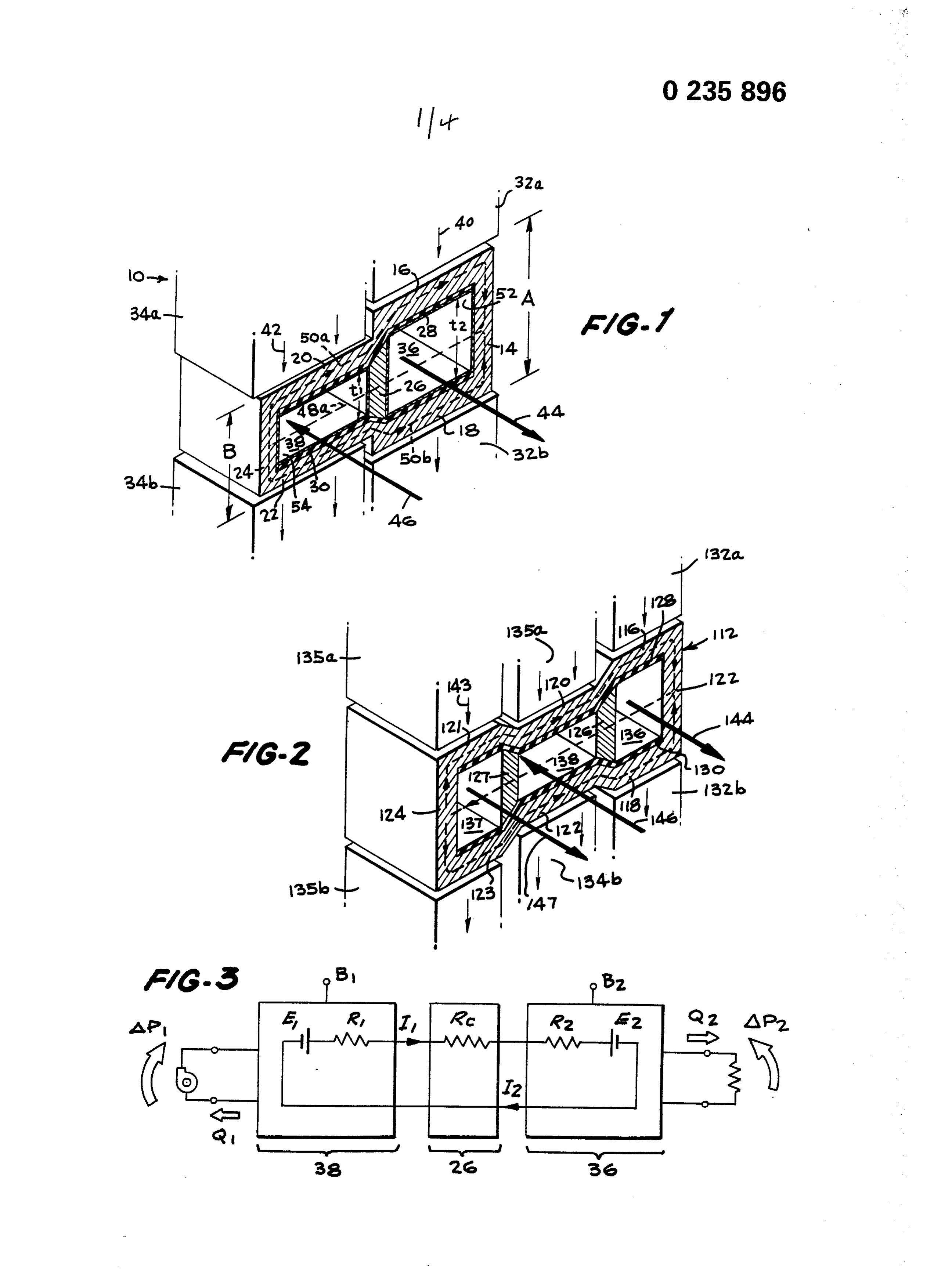
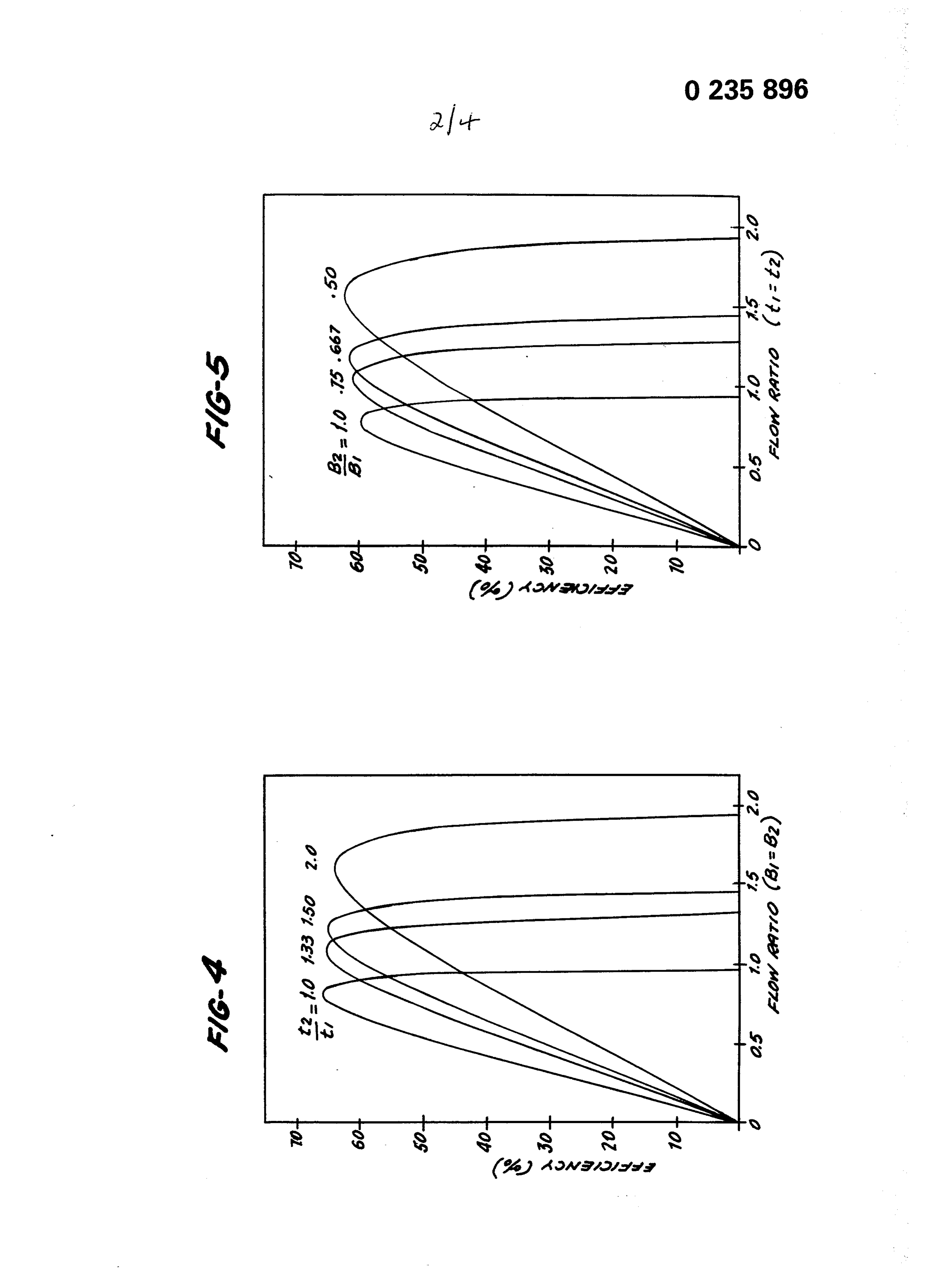
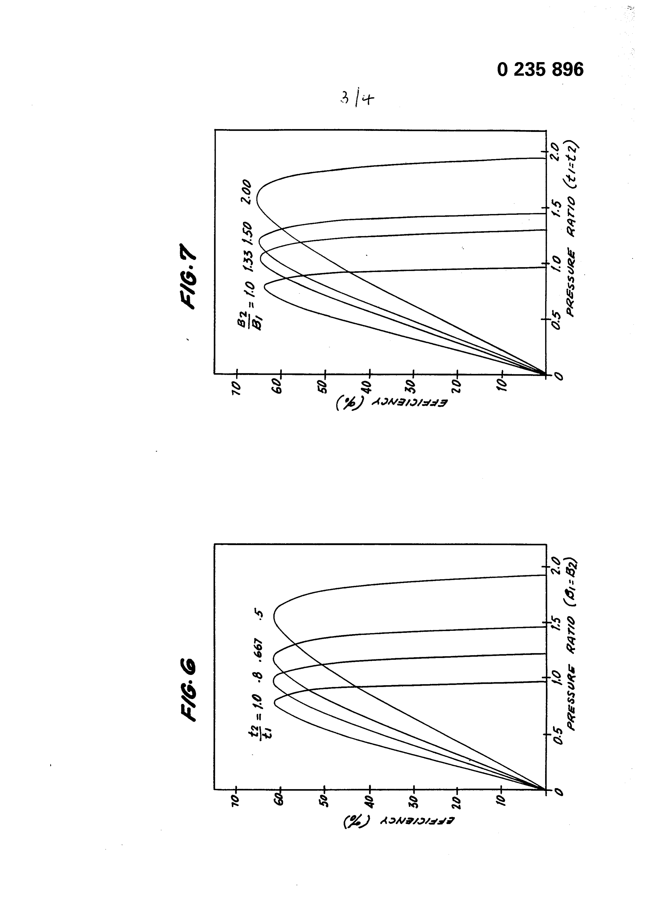
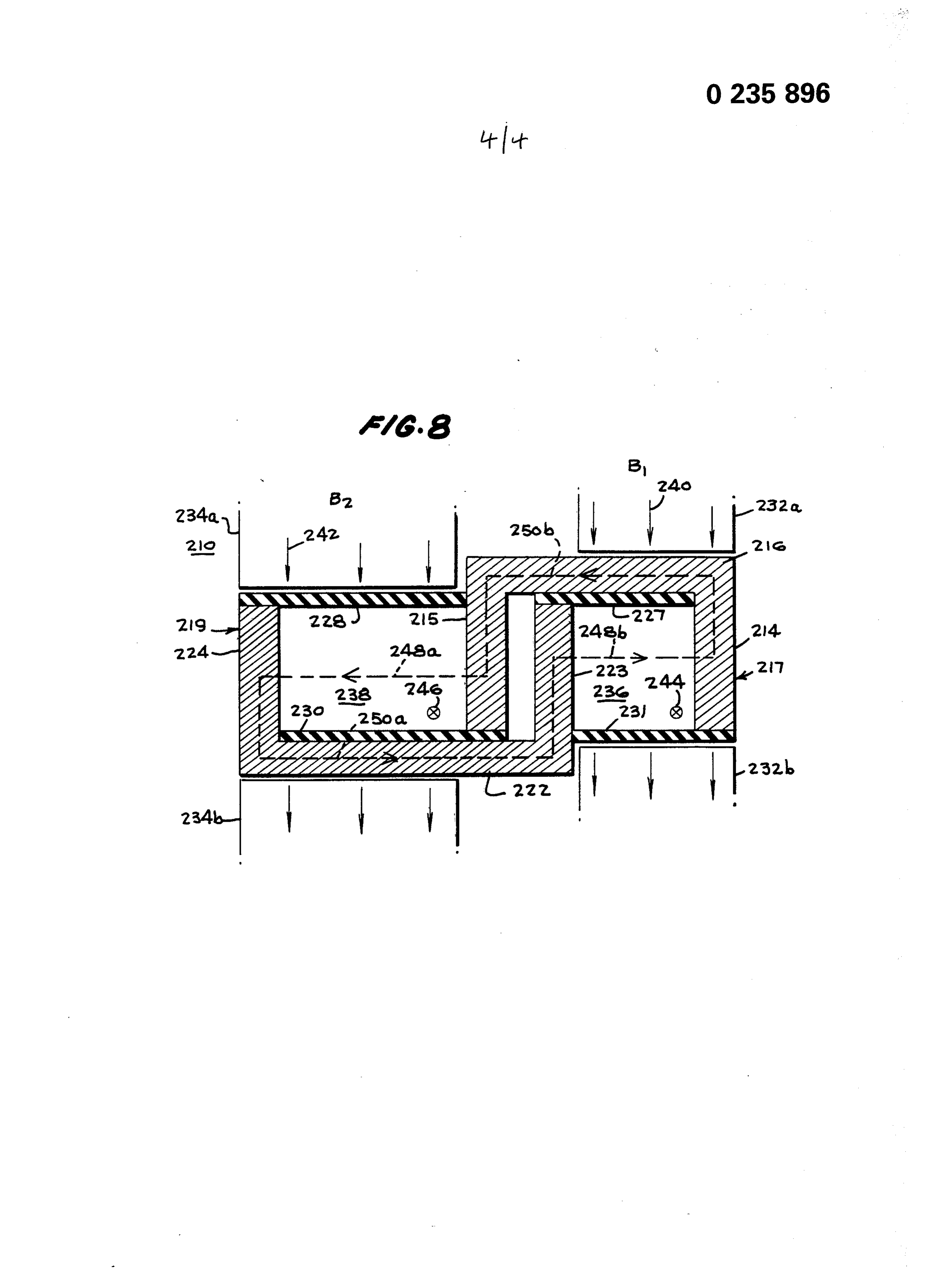
Figure 1 is a broken away, perspective view of a regulating EM f l o w coupler in accordance with the teachings of this invention;
Figure 2 is a broken away, perspective view of a 30 further embodiment of this invention in which a second pump duct is associated with the generator duct;
Figure 3 is a schematic diagram of the equivalent, electrical circuit of the regulating flow coupler of this invention acting as a flow/pressure amplifier;
Figure 5 is a graph illustrating the efficiency as a function of the ratios of flow rates in each of the 5 ducts of a flow coupler where each duct is of the same height;
Figure 6 is a curve indicating the efficiency as a function of the ratio of pressures where equal flux densities are established in the ducts of a flow coupler; 10 Figure 7 is a curve of the efficiency as a function of the ratio of the pressures where the ducts of a flow coupler have equal duct heights; and
Figure 8 is a side, sectioned view of a parallel flow coupler wherein the fluid flows in the pump and 15 generator ducts are in the same direction.
Page 23drawing sheetscan →
Page 24drawing sheetscan →
Page 25drawing sheetscan →
Page 26drawing sheetscan →
Page 27scan →
i / t »i l l European Patent
European search r e p o r t
Office
Documents considered to be relevant
Citation of document with indication, where appropriate, Relevant CLASSIFICATION OFTHE Category of relevant passages to claim APPLICATION (Int. a.*)
D,y gb-a- 745 460 (pulley) 1,5,6, h 02 k 44/00
* P a g e 1, l i n e 62 - page 3, line
Us-a-3 034 002 (carlson) 1,5,6,
* Column 1, l i n e 61 - column 4,
Technical fields
F R - A - 1 2 6 4 447 ( U . K . ATOMIC 14-18 SEARCHED (Int. CI.4)
Energy authority)
* P a g e 2, r i g h t - h a n d column, line H 02 K 56 - p a g e 3, left-hand column, G 21 C
The present search report has been drawn up for all claims
Place of search Date of completion of the search Examiner THE HAGUE 07-05-1987 TIO K.H.
CATEGORY OF CITED DOCUMENTS T : theory or principle underlying the invention E : earlier patent document, but published on, or
X : particularly relevant if taken alone after the filing date Y : particularly relevant if combined with another D : document cited in the application document of the same category L : document cited for other reasons A : technological background 0 : non-written disclosure & : member of the same patent family, corresponding P : intermediate document document
Provenance
- Collection
- Patents citing this work
- Pages
- 27
- Method
- pdftotext (the PDF's own text layer) + pdftoppm 300dpi page scans
- Patent office record
- patents.google.com →
- Source
- Google Patents citing-documents table
- Assignee
- Westinghouse Electric Corporation
- Published
- 1987-09-09
- Transcribed from
- patentimages.storage.googleapis.com →