

patent · US3412608A
Electromagnetic flowmeter
26 November 1968
Text
Drawings
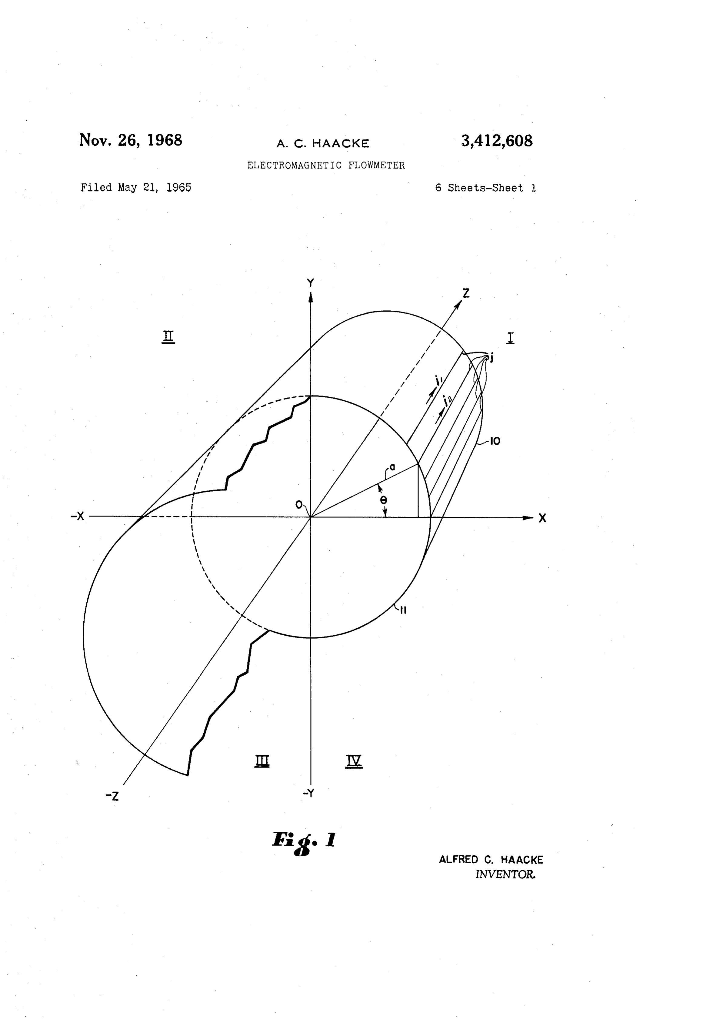
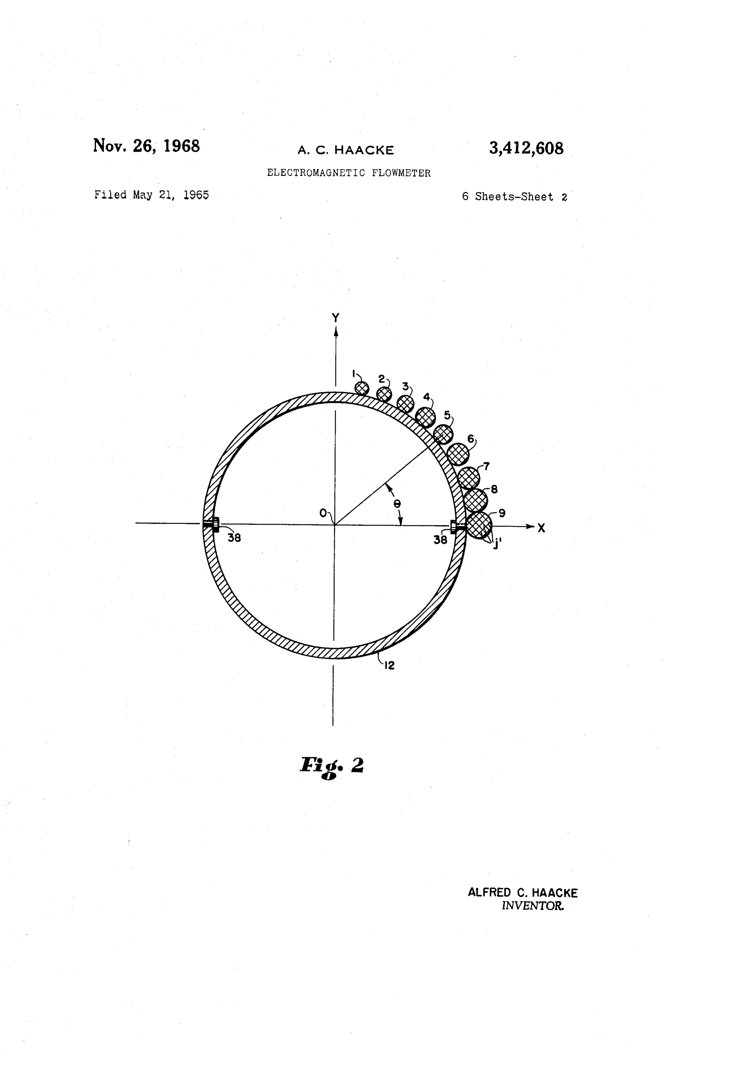
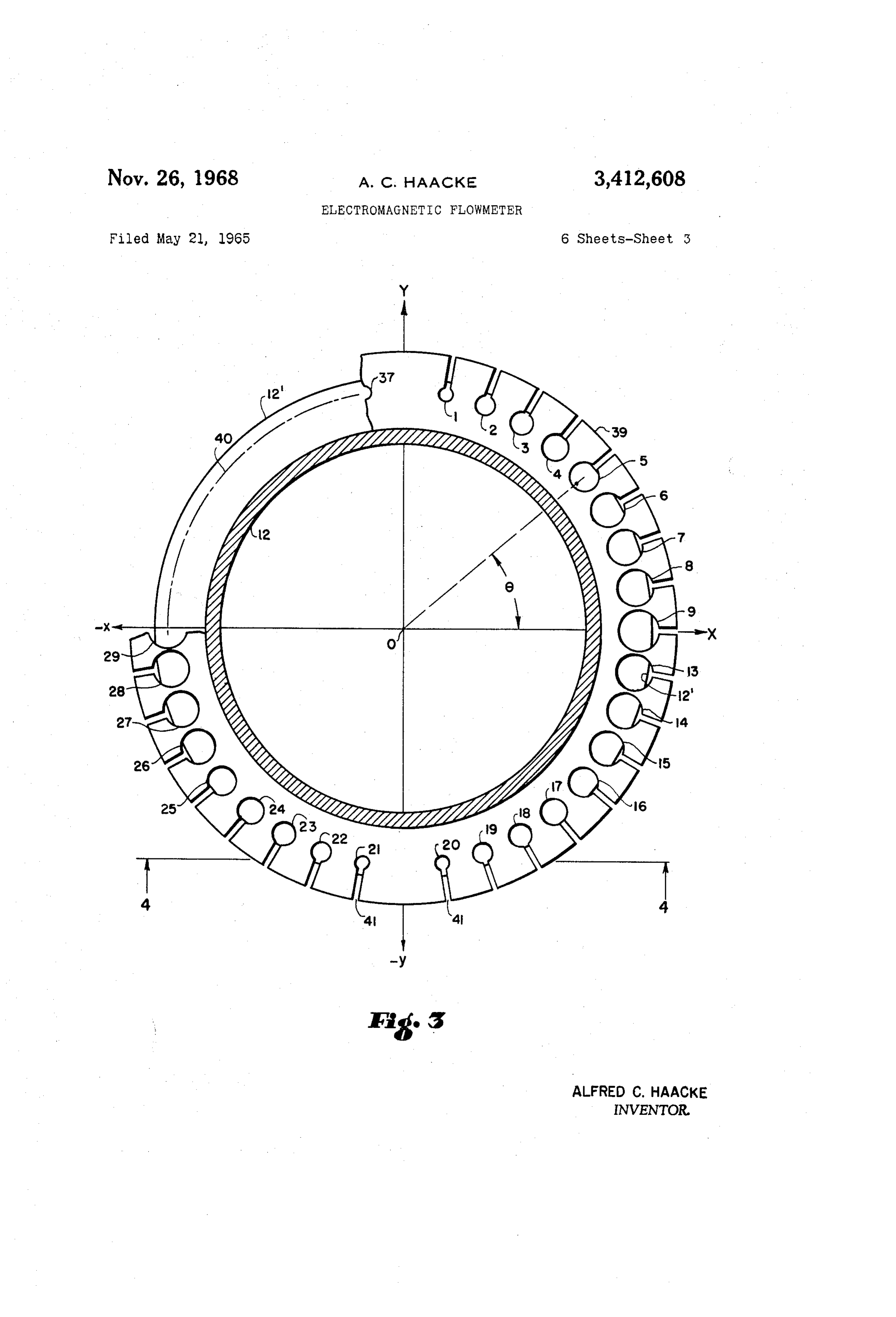
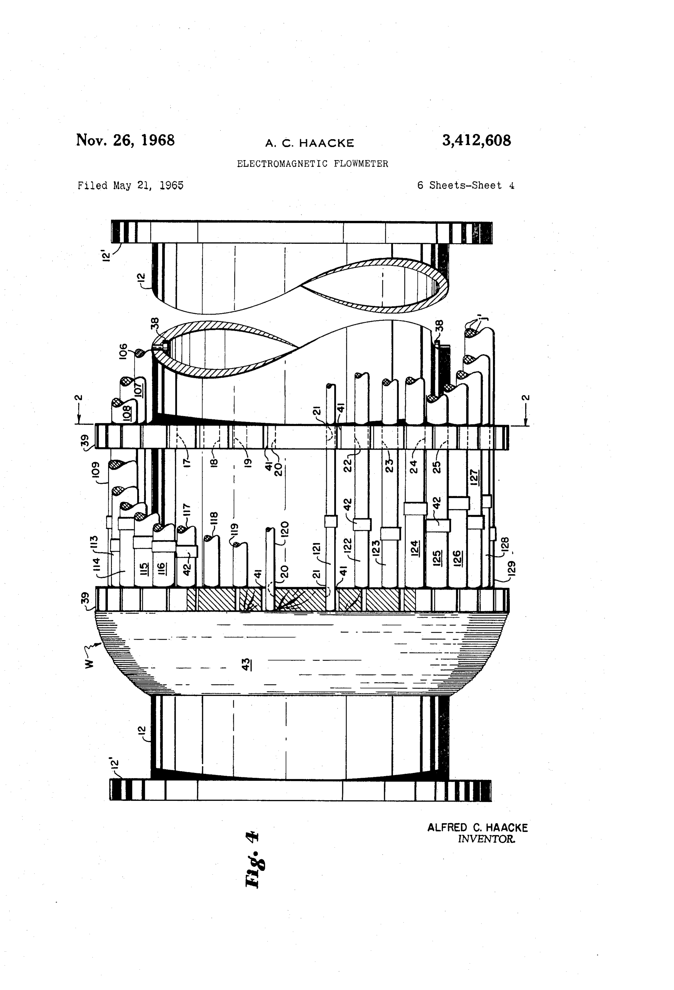
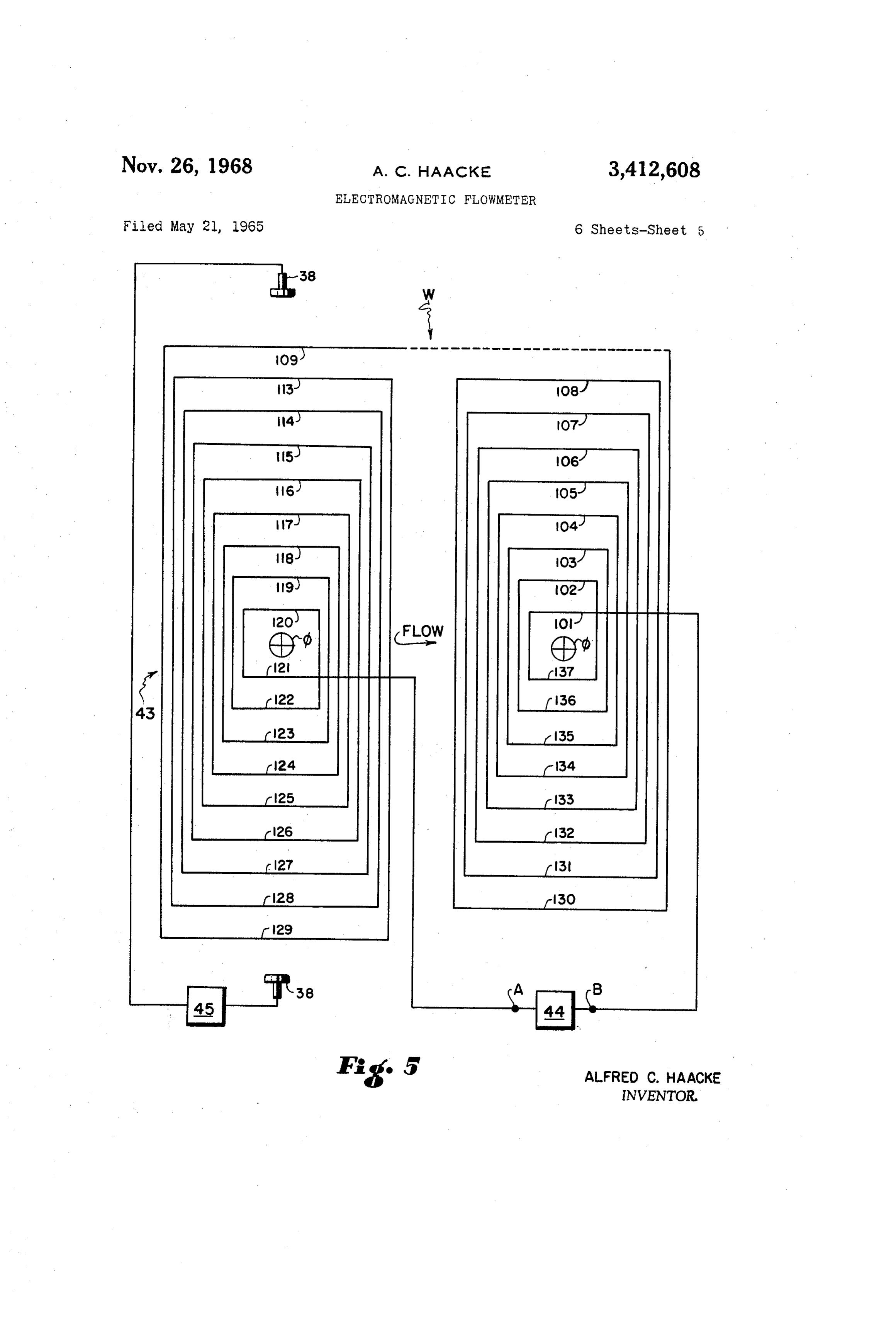
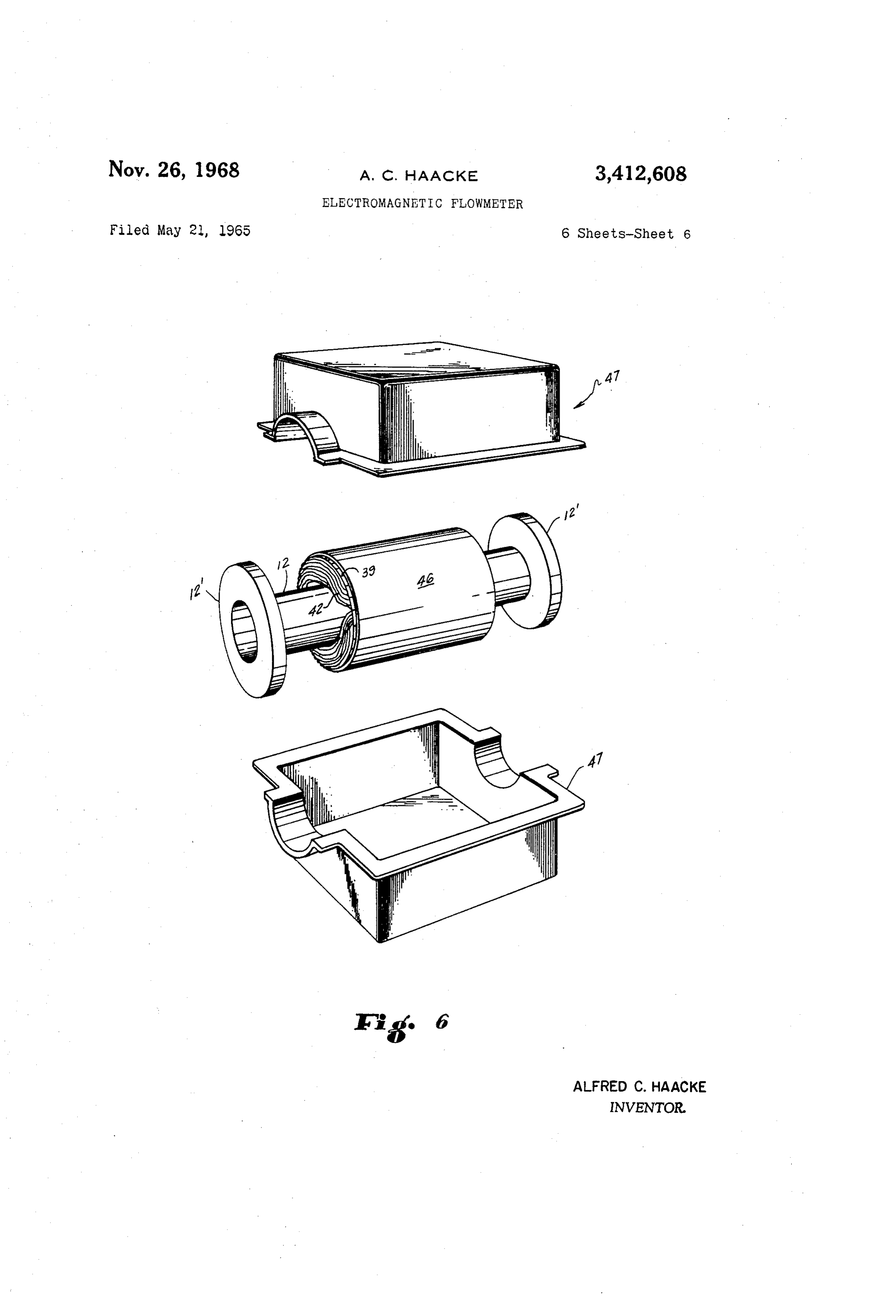
FIGURE 1 is a schematic view illustrative of the princi ples of the present invention.
FIGURE 2 is a partial diametral cross-section illustrat ing rudimentarily one mode of realizing the situation out lined in FIGURE 1.
FIGURE 5 is a schematic representation of the winding and electrode configuration that may be adopted in prac ticing the invention.
Page 1drawing sheetscan →
Page 2drawing sheetscan →
Page 3drawing sheetscan →
Page 4drawing sheetscan →
Page 5drawing sheetscan →
Page 6drawing sheetscan →
Page 7scan →
Electromagnetic flowmeter
Alfred C. Haacke, Greece, N.Y., assignor to Taylor in strument Companies, Rochester, N.Y., a corporation 5 of New York
The field windings of an electromagnetic flowmeter are provided in the form of a plurality of saddle-shaped coils, the sides of which are distributed about the periphery of the meter body parallel to the flow through the body, at spaced positions about the circumference of the meter body. The ampere turns of each winding vary with the cosines of the angles the coil sides make with respect to a line joining electrodes, the sides of the coil having the largest ampere turns lying over the electrodes. The sides 20 of the coils form more or less cylindrical bundles which may lie on the cylindrical periphery of the meter body, or be supported thereon by annular forms running circum ferentially of the body. While the winding needs no iron, it may be covered with a terminator of transformer steel 25 to insure isolation of the homogeneous field within the meter body from Earth's magnetic field, or other possible exterior magnetic influence.
This invention relates to electromagnetic flowmeters. One object of the invention is to provide a magnetic flow meter having new- and improved magnetic field creating structure. It is also the object of the invention to provide new and improved electromagnetic flowmeter structure that is at once simple, economical, sturdy, particularly suitable for the larger sizes of meters and capable of the highest quality of operation.
An electromagnetic flowmeter is basically a segment of pipe in combination with means to create a magnetic 40 field transversely through a cross-section of the bore of the pipe, and circuitry constructed and arranged to detect and utilize voltages across said cross-section normal to the direction of the magnetic field, there being electrodes in the wall of the pipe, which are exposed to the interior of the pipe bore, and to which said circuitry is connected. Generally speaking, the recited elements, except the said circuitry, form a substantially unitary sub-assembly more or less physically distinct from the said circuitry. The present invention resides in novel improvements 50 in said unitary sub-assembly, to wit, the pipe segment is provided with an electrical winding on its periphery con structed and arranged to approximate an electrical current distribution which at any point on the cross-section of said pipe has a value proportional to the cosine of the 55 angle represented by said point. As a consequence, no iron core or the like is needed to aid in establishing the proper magnetic field across the bore of the pipe, the magnetic field established is inherently highly uniform, and the only limitation on dimensions appears to be that 60 the pipe diameter (inner) need only be sufficiently large. For such sizes, the utility of the present invention is di rectly proportional to diameter, due to the fact that no iron structure is involved. This is to be contrasted to con ventional flowmeters, wherein the larger the diameter, the 65 heavier the iron structure required to generate the de sired magnetic field intensity.
As the voltage detecting and utilizing circuitry per se forms no part of the present invention, none will be de scribed herein, for such circuitry is well known and there 70 are many suitable forms thereof, of which those skilled in the art are aware. Suffice it to say that such circuitry may
Patented Nov. 26, 1968 have any or all the several functions of recording, indicat ing, integrating, controlling, etc., the flow of fluid through the pipe and the present invention is equally useful for all such functions.
FIGURE 1 is a schematic view illustrative of the princi ples of the present invention.
FIGURE 2 is a partial diametral cross-section illustrat ing rudimentarily one mode of realizing the situation out lined in FIGURE 1.
FIGURES 3 and 4 illustrate another mode of realizing the principles of FIGURE 1, FIGURE 3 being a diametral cross-section on line 3-3 of FIGURE 4, and FIGURE 4 being an elevation, partly broken away and including a partial section on line 4-4 of FIGURE 3.
FIGURE 5 is a schematic representation of the winding and electrode configuration that may be adopted in prac ticing the invention.
FIGURE 6 is a perspective view showing housing struc ture for a flowmeter according to the invention. In FIGURE 1, a cylindrical shell 10 is shown on a conventional set of mutually perpendicular axes x, y and z whose positive direction are respectively rightward, up ward, and away from the observer, and all of which inter sect at the origin o. Numerals I, II, III and IV denote the quadrants of the xy-plane.
The shell 10 has a circular cross-section 11 in the xy plane and its axis is coincident with the z-axis. The shell is supposed to be indefinitely long and composed of thin material of non-magnetic, electrically-conductive nature, and the cross-section 11 is supposed to be remote from any magnetic material.
Consider the generators of the shell, that is, the line segments i lying parallel to the z-axis and on the cylindrical surface of the shell and suppose that they represent parallel electrically conductive elements of the shell 10, and that each of said elements has currents i and i2 and so on in the positive z-direction flowing therealong. Conse quently, at any point within the shell 10, there will be a magnetic field normal to the xz-plane and in the direction of -y, and the total magnetic field intensity in any other direction will be zero.
It is desired, now, that the intensity B of the aforesaid magnetic field be the same anywhere within the shell 10. This condition will be achieved if the currents i and i2, and so on, in the elements i, vary sinusoidally about the periphery of the shell. Thus, starting with a given current io in an element i in the xz-plane, and taking the positive side of the x-axis and measuring the angle 6 counter-clock wise therefrom and around the z-axis, I provide the ele ments j in such form that (1) i=io cos 0, where i=the current in the element j in the xz-plane, and i=the current in the element j removed from the xz plane by the angle 0.
The consequence of the foregoing is that where
B=scalar magnitude in the -y direction of the mag netic field strength B, 2a=the diameter of shell 10, u-the magnetic permeability of the region of the shell, and
I=the total of all the currents flowing in the elements i. In other words, if the surface current density in shell 10 varies sinusoidally about the axis of the shell, then there will be a magnetic field whose direction and strength will be everywhere the same within the shell. In practice, it is necessary to deal with real conductors of finite dimensions, there are practical limits on the 8 amount of current that can be supplied (and handled), conductors making up the set, and which has the same and so on. Accordingly, certain of the elements i are current density therein as its fellows, so that, for exam approximated by means of pluralities of real conductors ple, the total current through set 9 is six times the total running parallel to each other, and to the z-axis, each current through set 1, and it acts as if it is through a plurality being spaced from the others and having as its hypothetical element j of FIGURE 1 at an angle of 0 general locus one of the said certain of elements i, where from the x-axis, whereas the set 1 acts as an element i, by the said pluralities are located at various angles 0 80° clockwise from set 9.
about the z-axis. In a formal sense, there is a tenth set at 90 (and a Each conductor of all said pluralities is supplied with 270°) counter-clockwise from set 9, but as this tenth set the same current i, and the number of conductors in each has zero total current, it is a virtual set and, having there plurality is in accordance with Equation (2), supra. Thus 10 fore no real existence, is omitted from the drawing. It (3) n= no cos 0, where is also to be observed that set 9 would also be counted n=the number of conductors in a given one of said as one of a like group of 9 sets (not shown) that would pluralities, be located in the lower right-hand quadrant. 6=the angle between another of said pluralities and said As shown in FIGURE 2, the centers of the conductor given one thereof, and sets are at varying distances from the z-axis. The equa n=the number of conductors in the said another one of tions set forth above when applied to calculate the values said pluralities. of n, do not take into account this variation. Taking the sets to be circular and to be made up of conductors 2c
In terms of FIGURE 1, then, the element i in the xz 20 in diameter, and the outer diameter of pipe segment 12 plane would be replaced, in effect, by no conductors, each to be 2a, the expression for the corrected value n' of any having the current i flowing therethrough, so that the n is, currentia would be inocos 0-in. (5)
Each plurality of conductors may be provided in the form of one side of a rectangular coil, thus leaving an 25 other side of said coil to provide a second plurality, since where d is the distance between any point P inside the the periodicity of the cosine function causes each value pipe segment 10 and the outer surface of the pipe seg of n to occur four times around the circumference of ment. Taking P on the z-axis as the optimum (for the shell 10. The remaining two sides of each coil are bent correction of Equation (4) is then too small for points to fit like saddles across the pipe and are made of such near the pipe wall, but by amounts that tend to be length as to then locate the first two sides at the angles 0 30 compensated by increase in the magnetic field as the and 180 6 from the positive side of the x-axis. It is suf wall is approached) the correction becomes: ficient approximation to infinite length if each of said first two sides is a diameter of the shell in length. (6) n'-n(I-ivn) In a typical case, values for B and 2a are given, since The corrections apply assuming that
B determines the field necessary to give the minimum voltage to be induced by fluid flow through the field in an electromagnetic flowmeter, and 2a corresponds to the (7) ’2 diameter of the flow passage of the flowmeter. This leaves which is the case in practice, since inequality (7) ex i and n as variables since 40 presses a lower limit for pipe-segment diameter (which is nearly the same as d, in this instance).
I = 4; X 720 Inequality (7) recognizes the fact that approximation As will be evident to those skilled in the art from the of current distribution in the elements i, by means of sets of conductors j', depends on the sets being of sufficient foregoing, the design and execution of an electromagnetic length and of sufficiently narrow cross-section, with re flowmeter sub-assembly according to the invention is quite spect to pipe segment diameter, to simulate the elements i. straightforward and simple. In addition, design and execu As a rule of thumb, one diameter of pipe segment is suf tion is susceptible to many variations, some of which will ficiently long and one-tenth said diameter, or less, is suf now be considered. ficiently narrow. However, extrinsic considerations such In FIGURE 2, the reference numeral 12 denotes the 50 as the voltage-detecting capability of the particular meter real counterpart of shell 10, the view being of a diametral circuitry to be used, the need to be able to use the same cross-section of a right-cylindrical segment of fiberglass meter circuitry in all sizes of meter sub-assemblies, power pipe or the like forming the flow path of an electromag available, allowable temperature rise in the winding, and netic flowmeter. The hatched circles numbered 1 through so on, will normally create a minimum size somewhat 9 represent cross-sections through sets of bundles of con 55 larger than that implied by inequality (7). ductors j', the hatching figuratively representing said con In a typical case, a meter sub-assembly in accordance ductors. The diameters of said circles decrease from 0=0 with the invention would have the following parameters: to 0-90, and the centers are spaced at 10 intervals c=0.028 inch (#15 A.W.G. copper wire, enameled) counter-clockwise from the x-axis. The diameter increase is intended to figuratively represent increase in number of 60 2a=10.75
B=50 gauss inches (outer diameter of pipe segment 12) conductors i' per bundle or set. By "figuratively,' I mean i=3 amperes that the verbally-described apportionment of conductors no=61.8 (chosen so as to give about 385 conductors). i' is only loosely portrayed by the hatched circles, since it is not feasible, in FIGURE 2, to portray with clarity Using these parameters in Equations (1), (3) and (6), the actual numbers of conductors and bundle-diameters 65 the following table of values of n and n' is obtained: in true proportions. nk In any event, as a practical matter, the numbers of conductors j', are taken as the integers nearest the cal 90 culated values thereof, for example, 10, 20, 38, 46, 52, 70 21.2 22 50, 59 and 60. Moreover, as the conductors are circular 70 60 in cross-section, they do not solidly fill the volume they 40 47.3 49 occupy, nor need this volume be more than approximately 30 round in cross-section. Nevertheless, it results that each 10 61.0 63 conductor set is in effect a single conductor whose cross 0. 61.8 64 section is the sum of the cross-sections of the individual 75 * Rounded to nearest integer.
Page 9scan →
Obviously, n' will be zero for 270; 11 for 100, 260 wire is normally round in cross-section). The actual num and 280; 22 for 110, 250 and 290, and so on. ber of conductors is of course the nearest integer to n, Equation (2) implies that the same set design data will as given by Equation (3), supra. Since the centers of the apply to pipes of all diameters, without requiring any holes are on the circle corresponding to arc 40, correc change in design of the voltage detecting circuitry. Thus, tion of n to n', by means of Equation (6), supra, is not if a is halved, B doubles. In practice, this is only approxi in order.
mately true, mainly because halving the inner diameter The number of rings 39 is not critical, it being only of the pipe segment less than halves the winding diameter, necessary that there are enough to maintain the bundles in a proportion that increases as diameter of pipe seg of conductors overall parallel with each other and, de ment decreases. Increasing i compensates for this, but 10 sirably, with the z-axis. It will be observed that the there is obviously a limit to how much increase in i there bundles are spaced from the external surface of pipe can be. Thus, by allowing i to be increased to as much Segment 12 thus allowing room for various circuit con as 5 amperes, the above figures can be used to design nections, such as to electrodes 38 to be made, without a series of meters using pipe segments ranging from interfering with the wire bundles.
around 6' O.D. and up, each of which uses the identical It will be observed, in connection with the discussion detecting circuitry design. Conversely, the approxima of FIGURE 1, that the hypothetical shell 10 is not the tion of Equation (2) in the practical case improves in interior surface of segment 12, but is rather the right cyl proportion as a increases, all other things remaining equal. indrical shell whose cross-section coincides with the The correction described supra is avoided in the form circle to which arc 40 belongs. This is the reason for the of the invention shown in FIGURES 3 and 4. FIGURE 20 correction applied in the case of FIGURE 2: the locus 4 shows a pipe segment 12 having circular flanges 12' of the centers of the conductor sets or bundles, i.e., of provided for inserting the segment 2 into a pipeline hav circles 1 through 9, and its fellows (not shown in FIG ing a liquid flowing therethrough. The winding W, located URE 2) is slightly elliptical, because the said circles are between the flanges has only about its left half shown, be tangent to the circular periphery of the outer surface of cause the other half thereof is the mirror image of its left 25 the pipe segment 12.
half. Also, the right-hand end of the pipe, except for its In FIGURE 3, the bundles of conductors i' are denoted flange 12, is also omitted, for the same reason. As those by the reference numerals of the holes through which skilled in the art will understand, in use, the segment they pass, plus 100. Thus, the bundle passing through 12 actually forms part of the said pipeline and will nor holes 24 (of the two rings shown and their two, unillus mally be of the same diameter as the section of pipeline 30 trated, right-hand counterparts), is bundle 124. The cir it forms part of. As indicated generally at 38 (in FIG cularity of the cross-section of each bundle may be rein forced by ties, such as are shown at 42, which are essen
URES 2 and 4) a pair of diametrically-opposed electrodes tially just bands or cords encircling the individual will be provided for the purpose of detecting the voltage generated across the inner diameter of pipe between the bundles, pulled tight around them and fastened in that state. The bundles need not exactly circular, and it is more electrodes. The segment 12 may be fiberglass, or other 3 5 important non-conducting material, or of non-magnetic stainless steel that their shapes and positions be maintained or other conductive material having a rubber sleeve or constant, the like lining and insulating its inner surface from the twoAsconductor can be seen from FIGURES 2, 3 and 4, each of the sets or bundles at 0° and 180° is common liquid flowing through the pipe, so as not to shunt the liquid (which may have quite low electrical conductivity) 40 toHowever, two of the quadrantal arrays of the conductor sets.
the n's could be computed for 10 degree in through the material of the segment 12.
In the construction of FIGURE 2, the windings are that tervals starting at 5 and ending at 185, and so on, so wound on suitable forms and then fitted to the pipe seg ductors. would be four sets each having nine bundles of con ment 12. In FIGURES 3 and 4, however, the forms are ing wiresAsto this arrangement provides space for connect electrodes inside the pipe (such as are briefly mounted on the pipe and the windings are then wound on to the forms, and these thereafter remain as winding sup indicated at 38) it may be adapted in the form of flow ports. Thus, I provide the rings 39, four in all (i.e., the meter sub-assembly indicated by FIGURE 2, where the two actually shown in FIGURE 4, plus another pair that conductor bundles are right on the surface of the pipe would be symmetrically located on the omitted part of Segment. As my novel electromagnetic flowmeter sub-assembly the construction illustrated by FIGURE 4). 50 needs no iron core, it results that the magnetic field inten
As is evident from FIGURE 3, rings 39 fit the outer sity obtained is basically a function of the number of circumference of the segment 12 snugly and are pro ampere turns in winding W. However, if the range of volt vided with a series of holes, there being shown holes 1 age difference between electrodes 38 is to be maintained through 9 (corresponding to the similarly-numbered circles of FIGURE 2), holes 13 through 29, and hole 37, 55 constant with respect to meter size, it results that ampere but there having been omitted the remaining holes that turns must decrease as meter size increases, which means would be numbered 30 through 36 in the upper left-hand decreasing the current per turn or decerasing the number quadrant of ring 39, FIGURE 3. In any pair of next adja of turns. The amount of wire L needed in any given case cent quadrants, the series of holes in the one quadrant can readily be computed, and, in the example given previ is in one to one correspondence, as to location and diam 60 ously, turns out to be about 1100 feet, or about twice as eter, with the series in the other quadrant. Thus, hole 23 much wire as would be used in a core-type meter of the is equal in diameter to hole 18, hole 18 is 60° clock same size and field, which latter meter, however, would wise from the x-axis, and hole 23 is 60 counter-clockwise have some 50 pounds of combined core and winding, as against about 11 pounds of winding of the meter of the from the x-axis, and all holes have the centers 10° apart said example.
on a circle whose center is 0, the intersection of the 65
Xy-axis and the center of the cross-section of segment 12. Moreover, the core of the prior art meter increases in Reference numeral 40 identifies about 90° of arc (in size as meter size increases, due to the need to provide the core with stability of shape. The usual core is in effect dashed line) of this circle.
Each of the said holes is slotted to and through the a ring deformed into a square or rectangular contour. As outer periphery of each ring 39 as indicated by the ref. 70 the meter size increases, the axial length of the ring, the erence numeral 41 in several instances, to enable the wire circumference of the ring, and thickness of the ring mate of the windings W to be laid into the holes. The area rial must be increased. Winding W, however, increases at of each hole is calculated to permit n=no cos 0 conduc a rate substantially less than the square because only the tors i' to be packed therein, solidly filling the hole (except, area of the coils forming winding W need increase. This of course, for the interstices necessarily left because the 75 is due to the fact that the effect of the core is to bound a
Page 10scan →
Volume, i.e., it is more or less an open-ended box sur and finish the coil defining bundles 101 and 137. Instead, trounding the flow path of the meter, and as the said volume the start lead may wind half the coil defining bundles 109 increases, the volume of the box and the thickness of the and 129, counter-clockwise, say, and out toward the ob Walls of the box necessarily increase. The coils of winding server so that a final lead results after the coil defining W merely provide the conductive elements i, and though bundles 120 and 121 is wound. Another start lead starts the said coils therefore perform the field producing func the other half of the coil defining bundles 109 and 129, tion of a core plus winding, their physical nature is not and proceeds counter-clockwise, but out and away from Such as to require them to have the form of a continuous the observer until the winding of the coil defining bundles Wall around a volume corresponding to that bounded by 101 and 137 terminates in another finish lead. The two the core. O finish leads are connected together and to one of the ter FIGURE 5 represents one winding scheme that may be minals A and B, and the two start leads are connected adopted. Each horizontal line corresponds to a bundle together and to the other of said terminals. In terms of of conductors i', and has the reference numeral of the FIGURE 5, insofar as winding sense is concerned, it is as bundle to which it corresponds, although the number of if one of the right half of the winding W has been rotated turns in each bundle is not portrayed. Thus, the reference 5 180 about a vertical axis. As compared to the series case numerals 113 through 129 represent the similarly num of FIGURE 5, the just-described series-parallel connection bered bundles of FIGURE 4, whereas the bundles 101 causes the winding to require twice the current in order through 108, and 130 through 137, represent the similarly to produce the same field.
numbered bundles (only some of which are represented Considering the principles illustrated in FIGURE 1, it in FIGURE 4) which would be on the other side of pipe : will be seen that the conductor bundles are the practical segment 12 as shown in FIGURE 4. As FIGURE 5 repre way of simulating the theoretical surface current distribu Sents the latter group of bundles shifted rightwardly, so tion in the shell 10, for the same current flows in every as not to be obscured by the bundles 113 through 129 conductor of the bundles (each conductor has the same the line denoting bundle 109 has been continued in dashed resistivity, of course). However, it is conceivable that line for about the extent of the shift. each of the lines denoting bundles in FIGURE 5 could The vertical lines 43 in FIGURE 5, which interconnect represent a single conductor whose resistance is propor the bundle lines, abstractly represent the parts of the wind tional to cos 0. However, these conductors would have ings piled in Saddle fashion on the surface of pipe segment to be parallel-fed, in general (although like-resistance 12 at the ends of the windings, as for example, as shown conductors could be in series with each other), and at 43, more or less naturalistically in FIGURE 4. 30 though the desired character of field would result, an Reference numeral 44 denotes a suitable source of cur impractically large amount of current would be required, rent having terminals A and B. Supposing the current to in order to obtain this field. The quantitative aspects of flow out of terminal A, it proceeds first through bundle the situation are that actual embodiments of the meter, 121, then bundle 120, going always clockwise, finally in the form illustrated in FIGURES 3 and 4, may have leaving from bundle 101 to return to source 44 via ter windings rated at 300-400 volt amperes, for energization minal B. by a 117 volt AC source. Thus, the concept just described, Considered in respect to FIGURES 3 and 4, the direc of replacing the bundles with single conductors, implies tion normal to the view of FIGURE 4 is along the y-axis. current up to around 3000-4000 amperes (figured at, say, Hence, taking into account the fact that starting with about 3 to 4 amperes per wire per bundle). However, it bundles 120 and 121, each successive pair of opposite 40 would not be impractical to cut down the number of bundles is centered on the contour of the circle including conductors in some of the sets of bundles by increasing arc 40, the said successive pairs are successively further the current through each conductor in these bundles. and further from the observer, and proceed in the positive Thus, taking the largest bundles to be about 240 ampere y-direction. Accordingly, at any instant the direction of turns with 60 conductors, the number of conductors the magnetic field intensity due to the pairs of opposite therein could be reduced to 15 if these particular con bundles is in the y-direction and has the same sense for ductors were energized at 16 amperes per conductor. One each pair of bundles. (The contribution of the vertical con advantage of doing this would be to reduce bundle size, ductor lengths, as at 43 is negligible, as it is assumed that for the conductivity of wire increases as its cross-sectional the bundles 101 et al. are long enough that in cross-sections area, other things remaining equal. through the electrodes 38 the field is uniform, and not 50 Inequality (7), supra, indicates that if the voltage de affected by the distribution of the conductor lengths 43 tecting capability of circuitry 45 can be as sensitive as we et al. running transverse to the z-axis, i.e., the axis of please, then the lower limit on meter diameter is given segment 12.) by wire size. Thus, using #40 AWG and the n's exem The circled crosses denoted by reference character (b. plified previously, a pipe segment 12 on the order of indicate that the direction of the flux due to the winding W 0.1 inch outer diameter could be used (taking the ratio is away from the observer, so that terminal A is positive. of largest bundle diameter (the 0 bundle) to pipe seg The arrow marked FLOW represents the direction of flow ment diameter to be, permissibly, 1 to 10). Again, with of electrically conductive fluid between the two halves of unlimited voltage detecting capability, any diameter of winding W, and in contact with the electrodes 38. Box 45 pipe segment 12 capable of passing through a given wind represents suitable circuitry constructed and arranged to 60 ing could be used.
respond to difference in voltage between electrodes 38. It is evident that the advantages of a flowmeter con Since by Faraday's principle, the flowing fluid acts like a structed in accordance with the principles of the present succession of vertical conductors moving transverse to the invention are generally in direct proportion to the diam magnetic flux in the direction g5, voltages will be induced eter of the pipe segment defining the flow path through in the fluid between electrodes 38 in proportion to the 65 the meter. While quite large prior art meters have been volumetric rate of flow. It therefore results that the said constructed using iron cores to aid in creating the mag difference in voltage arises, in proportion to the volumetric netic field of the meter, I consider that the present inven rate of flow, and circuitry 45 accordingly responds in tion makes possible the construction of meters larger accordance with the volumetric flow rate. As is known, than any core-using meter heretofore constructed or the flow may be in the opposite direction, and/or the polar 70 thought feasible to construct at this time. ity of Source 44 may be reversed, and source 44 may be The main precaution to be observed in operation of either AC or DC, though it is generally AC. my novel flowmeter is to prevent distortion of the field Another possible arrangement of the winding W is a produced by windings W. Thus, nearby ferrous objects, parallel one, wherein the start and finish leads do not the earth's magnetic field, and the use of a squarish respectively begin the coil defining bundles 120 and 131 75 shaped housing of ordinary steel on the meter may distort 11 the field. In addition, the usual kind of steel suitable for trodes being inside said shell at a point where said angle housing purposes will absorb considerable amounts of is zero degrees, the other of said electrodes being inside power from the field. said shell at a point where said angle is 180 degrees, and As a solution for such problems, according to the inven there being said conductive means of said shell along tion I provide the terminator 46, as shown in FIGURE 6. generators of said shell corresponding to said points. The terminator 46 is simply a cylindrical casing of steel of 2. The invention of claim 1, wherein said conductive the kind and thickness used in making transformer lami means comprises a plurality of electrical conductors paral nations. This type of steel absorbs a minimum of power lel3.to The the axis of said shell.
invention of claim 1, wherein said conductive and produces a minimum of harmonics, when exposed to changing magnetic fields (for which reasons it is used 10 means comprises a plurality of electrical conductors in transformer construction, of course). Accordingly, the parallel to the axis of said shell, and the number of con field due to winding W, instead of terminating at infinity, ductors in the neighborhood of a point on said shell be terminates in terminator 46 in a manner symmetrical ing proportional to n cos 0, where n is the number of con to the z-axis, so that no distortion of the field within pipe ductors in the neighborhood of a given point on said segment results from the presence of terminator 46. Since 5 shell and 6 is the angle between the radii of said shell the said field terminates in terminator 46, it is not affected containing said points.
by the usual sources of distortion external to it, such as 4. The invention of claim 1, wherein said conductive steel pipes, etc., and the earth's field. Moreover, a con means comprises a plurality of electrical conductors ventional steel housing 47 which may have quite unde parallel to the axis of said shell, and the number of con sirable characteristics, in terms of shape, harmonic pro 20 ductors in the neighborhood of a point on said shell being duction and power absorption, but otherwise desirable proportional to n cos 0, where n is the number of con from the point of view of cost, and protection of the ductors in the neighborhood of a given point on said meter from mechanical, chemical and other influences shell and 9 is the angle between the radii of said shell in its vicinity, may be provided around the terminator containing said points, said plurality of conductors being 46, serving incidentally as magnetic shielding around ter arranged in a plurality of bundles of conductors, each minator 46, also. such bundle having therein in cos 9 conductors. The functions of housing 47 and terminator 46 can be 5. The invention of claim 1, wherein said conductive combined into one, effectively eliminating terminator 46 means comprises a plurality of electrical conductors paral and constructing housing 47 in the shape of terminator lel to the axis of said shell, and the number of conduc 46, but at the price of absorption of power from the tors in the neighborhood of a point on said shell being field of winding W and introduction of harmonics into proportional to in cos 0, where n is the number of conduc the total field due to winding W, if ordinary steel be tors in the neighborhood of a given point on said shell used. The illustrated parallelepipedal form of housing 47 and 9 is the angle between the radii of said shell contain would distort the field in the absence of terminator 46. ing said points, said plurality of conductors being ar Of course, if the meter is to be used in a stable environ 35 ranged in a plurality of bundles of conductors, each such ment wherein its orientation and the magnetic entities in bundle having therein in cos 0 conductors, and each said the environment are not subject to change, the meter point being the center of a bundle. may be calibrated for said evironment, whereby a non 6. In an electromagnetic flowmeter constructed and ar magnetic material may be used for housing 47 and the ranged for flow of liquid therethrough, said flow meter terminator 46 may be dispensed with. 40 including, in combination, means for creating magnetic In any event, the terminator 46 is not to be confused flux through and transverse to said flow and means for with conventional magnetic shielding such as would be detecting voltages generated by the interaction between offered by Mu-Metal, or the like, materials which are said flux and the flowing liquid it traverses; the improve costly, difficult to fabricate, and must be treated with ment wherein the first said means comprises conductive great care in order to avoid deleteriously changing their means effectively defining an electrically-conductive cy shielding properties, whereas terminator 46 may be lindrical shell surrounding said flow and having its gen formed by any convenient technique, need not be sub erators lying parallel to the direction of said flow; said jected to any special treatment nor be given any special conductive means comprising a plurality of electrical con care in use, and is relatively inexpensive. ductors parallel to the axis of said shell, and the num While it is evident that the need for terminator 46 50 ber of conductors in the neighborhood of a point on said would partly be eliminated by DC energization of wind shell being proportional to n cos 0, where n is the number ing W, it is generally the practice to energize winding W of conductors in the neighborhood of a given point on from an AC source, whereby to obviate problems due to said shell and 0 is the angle between the radii of said polarization of the electrodes 38, having to detect DC shell containing said points, said plurality of conductors voltages, and so on. being arranged in a plurality of bundles of conductors, I claim: each such bundle having therein in cos 0 conductors, and 1. In an electromagnetic flowmeter constructed and ar there being forms supporting said bundles around said ranged for flow of liquid therethrough, said flow meter flow of liquid, each said form comprising an annulus including, in combination, means for creating magnetic provided with spaced circular holes therethrough the axes flux through and transverse to said flow and means, in 60 of which are coincident with generators of said shell, and cluding a pair of electrodes, for detecting voltages gen the radii of which are such that any given one of said erated by the interaction between said flux and the flow holes can contain substantially just n cos 8 conductors, ing liquid it traverses; the improvement wherein the first and said forms being so aligned that holes of the same said means comprises conductive means effectively defin size have their centers on the same generator of said shell, ing an electrically-conductive cylindrical shell surround and said bundles being passed through said forms via said ing said flow and having its generators lying parallel to holes.
the direction of said flow; said conductive means being 7. The invention of claim 1, wherein said conductive constructed and arranged such that the electrical current means comprises a plurality of electrical conductors density at any point of said shell is proportional to the parallel to the axis of said shell, and the number of con cosine of the angle between a given radius of said shell 70 ductors in the neighborhood of a point on said shell be and the radius thereof that includes said point, and such ing proportional to n cos 0, where n is the number of that electrical current through said conductive means is conductors in the neighborhood of a given point on said parallel to the axis of said shell; the dimensions of said shell and 0 is the angle between the radii of said shell containing said points, said plurality of conductors being conductive means radially of said shell being small com arranged in a plurality of bundles of conductors, each pared to the radius of said shell, and one of said elec 12 such bundle being spaced from the other around the by the interaction between said flux and the flowing liquid periphery of said shell, and each such bundle having there it traverses; the former said means including a plurality in in cos 0 conductors. of elongated electrically conductive means, said plurality 8. An electromagnetic flowmeter comprising an array being distributed parallel to one another about the pe of linear conductors arranged to effectively define a right 5 riphery of said pipe segment, and said elongated electri cylindrical, electrically conductive shell, said array being cally conductive means being constructed and arranged formed of a plurality of sets of said conductors wherein such that predetermined electrical current densities there each set is a bundle of substantially parallel conductors, in provide a uniform field inside said pipe segment; and and said sets being positioned so that the length of each there being mounting means mounting said elongated elec set is spaced substantially one radius of said shell from O trically conductive means on said pipe segment, said the axis of said shell, and each said set having just so mounting means embracing each said elongated electri many conductors therein that if current flows through cally conductive means individually and fixing same in each conductor thereof, the total current through said position with respect to its fellows and to said pipe seg each said set is substantially proportional to the cosine of ment.
the angle between a radius of said shell terminating at 10. The invention of claim 9, wherein said mounting said each said set, and a given radius of said shell; means means comprises a plurality of annuli mounted on said for conducting fluid into one end of said shell, along the pipe segment transverse to said elongated electrically con axis of said shell, and out the other end thereof; a pair ductive means, the latter passing through the material of of electrodes arranged within said shell at positions where said annuli, each of said annuli surrounding the periphery in said fluid would flow between said electrodes; and be 20 of said pipe segment and being spaced from one another tween which electrodes a potential difference would arise along the length of the said pipe segment. where an electrically conductive fluid to flow through said shell and cut magnet lines of force across said shell due References Cited to current flowing through said conductors, and there be UNITED STATES PATENTS ing a said set of conductors at the zero degrees radius of 2,771,771 11/1956 Kamp et al. --------- 73-194 said shell, and a said set of conductors at the 180 degree 3,260,868 7/1966 Brenner --- 336-225 X radius of said shell, one of said electrodes being located 3,274,831 9/1966 Cushing ------------- 73-194 on said Zero degrees radius and the other of said elec 3,034,002 5/1962. Carlson ------------- 73-194 trodes being located on said 180 degree radius.
9. In an electromagnetic flowmeter having a cylindrical 30 FOREIGN PATENTS pipe segment constructed and arranged for flow of liquid 1,308,097 9/1962 France.
therethrough, said flow meter including, in combination, means for creating magnetic flux through and transverse RICHARD C. QUEISSER, Primary Examiner. to said flow and means for detecting voltages generated C. A. RUEHL, Assistant Examiner.
Provenance
- Collection
- Patents citing this work
- Pages
- 12
- Method
- pdftotext (the PDF's own text layer) + pdftoppm 300dpi page scans
- Patent office record
- patents.google.com →
- Source
- Google Patents citing-documents table
- Assignee
- Taylor Instrument Co
- Published
- 1968-11-26
- Transcribed from
- patentimages.storage.googleapis.com →