

report
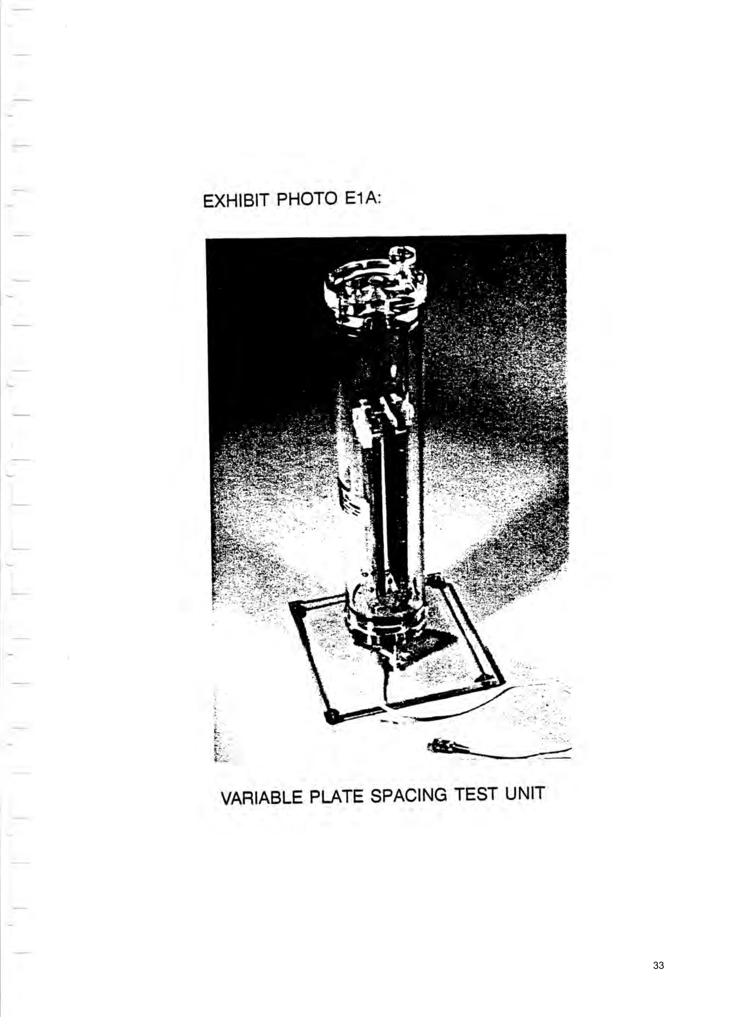
Exhibit photographs of the test units
1 January 1995
Text Report a misread
Drawings
Page 33drawing sheetscan →
Page 34scan →
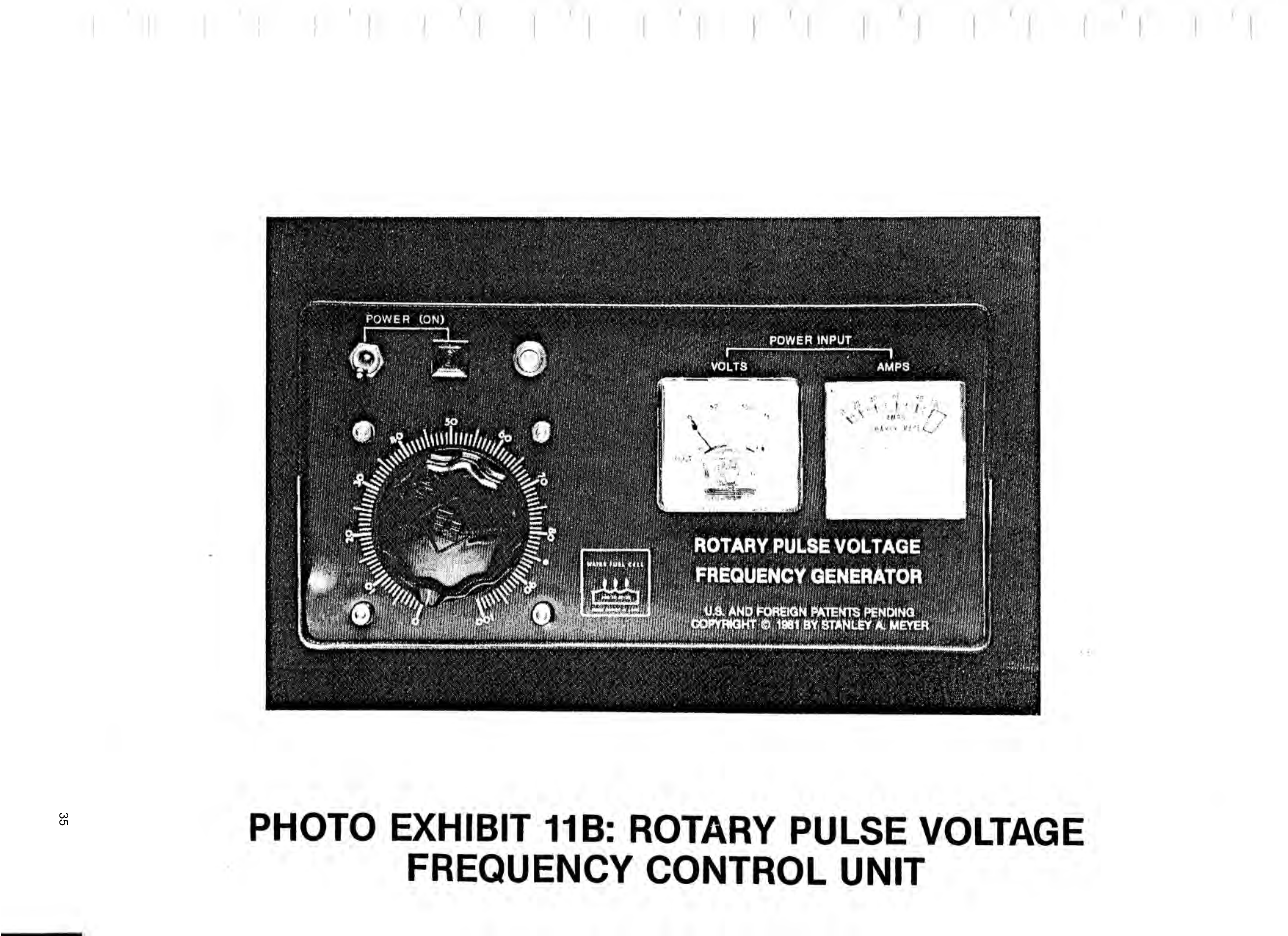
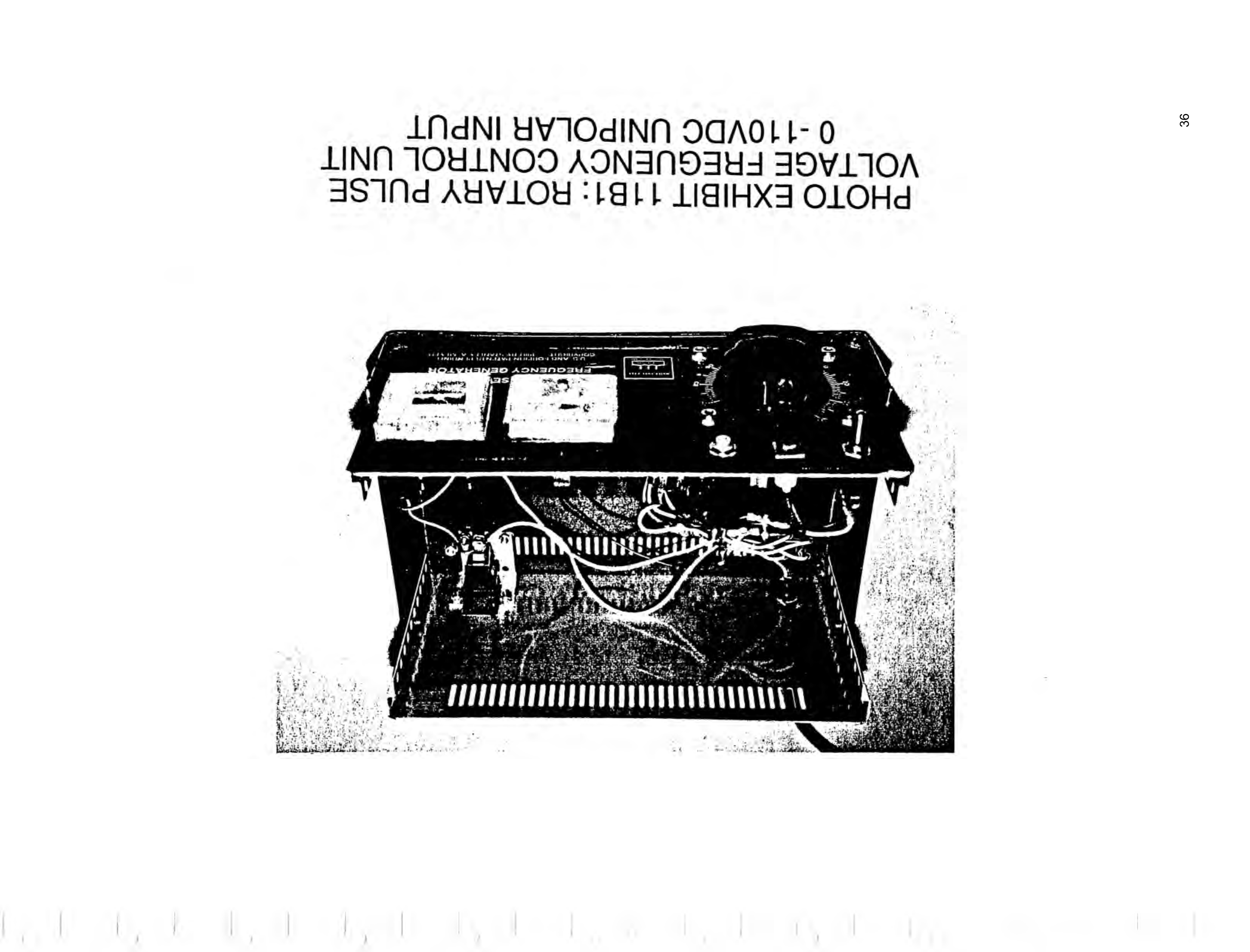
Electrical Polarization Process Control Unit
(Photo Exhibit 11)
Figure 11E: Variable-Plate WFC Fuel Cell Electrical Hookup (Top View)
Variable Plate
WFC Fuel Cell
(Photo Exhibit E1A)
Page 35drawing sheetscan →
Page 36drawing sheetscan →
Page 37drawing sheetscan →
Page 38drawing sheetscan →
Page 39scan →
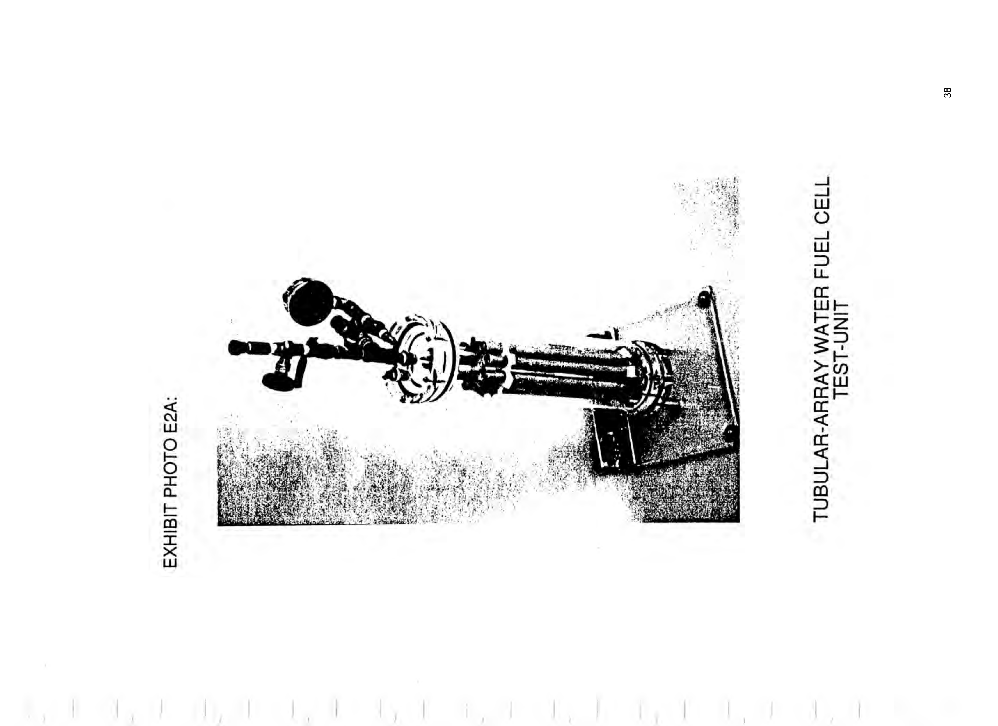
Tubular Array
110V AC Switch Arra Water Fuel Cell Wall-Plug Y =f (Photo Exhibit E2A)
Isolated Pickup Circuit Output =H ©) ©2
(Optional VIC Rotary Circuit 8-11) —f oak Wall-Plug
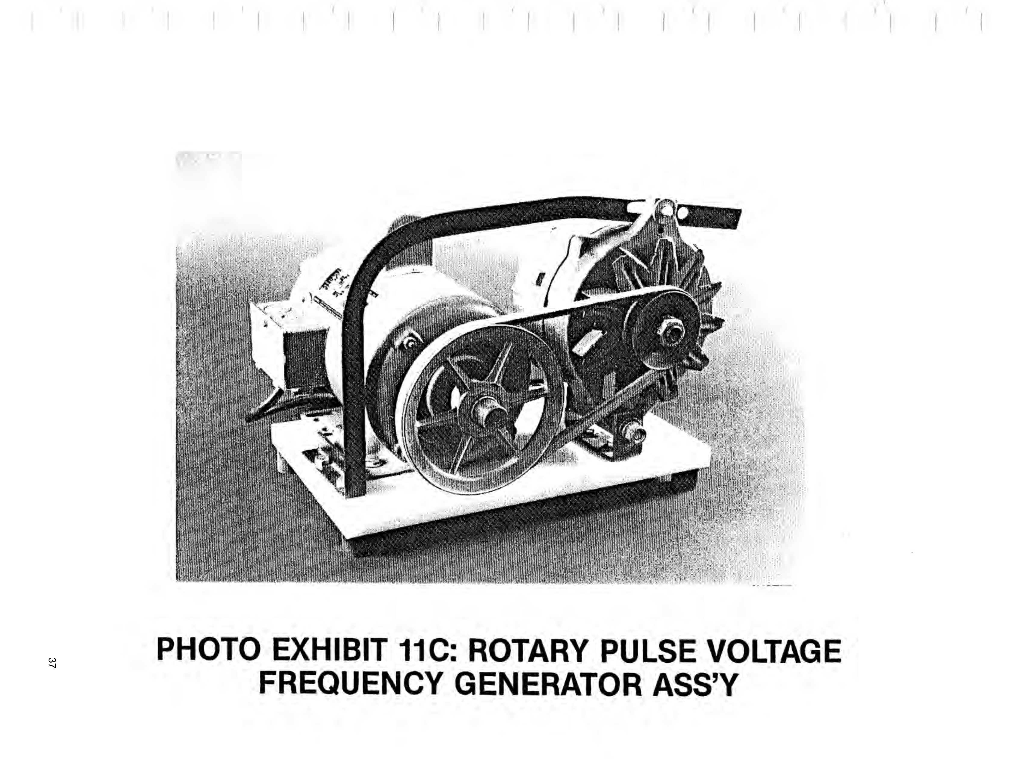
Constant Speed ms
Electric Motor Field Windin
Electrical Terminal i —=
Conventional
Alternator
—— Rotary Pulse Voltage =e Frequency Control Unit \ (Photo Exhibit 11B)
Belt Driven
Photo Exhibit 11C
Figure 11D: Tubular-Array WFC Fuel Cell Electrical Hookup (Top View)
Provenance
- Pages
- pages 33–39 of 140
- Binder
- WFC Project Binder 423-DA
- Method
- pdftoppm 300dpi + tesseract 5 (eng), orientation-corrected
- Source
- WFC International Independent Test-Evaluation Report (1995), scanned binder