

report
Circuit schematics and control drawings
1 January 1995
Text Report a misread
Page 21scan →
RE: Electrical Polarization Process WFC Memo 420
Exponential
Hydrogen gas-yield
Water fuel cell
“ MODE OF OPERABILITY "
| voltage dissociation of the water molecule
) 2 volts
g , AMP POTENTIAL | INEAR HYDROGEN GAS-YIELD
= retricting
Linear amp flow
WFC ELECTRICAL POLARIZATION PROCESS PRIOR ART ELECTROLYSIS PROCESS (ELECTRICAL ATTRACTION FORCE OF OPPOSITE POLARITY) (CHEMICAL INTERACTION CURRENT DEPENDANT) REQUIRES NATURAL WATER ONLY REQUIRES ELECTROLYTE ... DEAD SHORT CONDITION
Electrical Polarization Process Vs Prior-Art Electrolysis Process
Page 22scan →
RE: Electrical Polarization Process WFC Memo 420
To voltage regulator unipolar voltage wim
Pc9xd card / waveform varaible amplitude gated
is] UNIPOLAR PULSE-FREQUENCY
POWER-ON 104 CIRCUIT VARIABLE b,
Switch — breaker transformer (a)
0-110 vac full bridge blocking meter
Oo—co o—d RECTIFIER
; diode
vane © i
WwW) VOLTAGE
Meter
Variable pulse-width
Triggering circuit pc9xb card
Magnetic coupling
O) magnetic. field
Induction core
Variable plate
(water fuel cell)
Photo exhibit (e1a)
Excitor plates positive
(voltage zones) voltage
Stainless steel t304 potential
Material
Water =
Negative ~~
Voltage
Potential
Amp inhibiting circuit
Resonant charging chokes
Bifilar-wrap coils about an inductor core
“* INCREASED COIL LENGTH EQUALLY
F ist . INCREASES APPLIED VOLTAGE LEVEL/ AMP Electrical Polarization Process Control Unit RESTRICTION SINCE INDUCTANCE / CAPACITANCE
(Photo Exhibit 11 / 11A) INCREASES PROPORTIONALLY
Figure 8xa: voltage intensifier circuit (vic)
Copyright © 1981 By Stanley A. Meyer
Stanley A. Meyer 1-6
Page 23scan →
RE: Electrical Polarization Process WFC memo 420
Resonant
Charging choke (c)
Blocking (resistive coil wire r2)
Diode (b)
Variable
“ EXCITOR ARRAY (ER)
Ww\. / (capacitor)
Secondary
Pickup coil (a)
ne? (RESISTIVE WIRE-COIL R1)
Primary
Coil (g) natural water
/ (dielectric liquid)
Isolated
Pulsing
TRANSFORMER j pitas ore ate RESONANT CHARGING CHOKE (D)
(j) (resistive coil wire r3)
FIGURE 8XA\1:Voltage Intensifier Circuit (AA)
Copyright © 1981 By Stanley A. Meyer Stanley A. Meyer 1-7
Page 24scan →
8-1 Johay “W Agjueys sahaw “y Aajuers Ag 1861 © 1UBuAdoD SILVWAHOS GHV9 GX690d HOLVINDAY ADVLIOA :-GX6 SHNDIS
WUP [04jJUOD SS890Jq UONEZUL|O,g JedW}O9|/y mF na eat Lapa
DOA zt [tL BEVLIOA QX64d LISIHXS OLOHd
35a014a T1Nd YAWHOISNVUL
Yolvindsy
oons [b} FOVLIOA ZL
WHOSSAVM f
ADVLIOA HV IOdINN
O2p OWSW OAM SS800J4 UOHEZULIO, JB91}99/9 :4H
Page 25scan →
RE: Electrical Polarization Process WEC Memo 420
12 VCC
POT 10
Pulse
DECADE DECADE Es 1K 555 COUNTER COUNTER COU Es
Timer to voltage
ry 2 7 2 7 INTENSIFIER
Circuit 8xa
Pulse o
Selector 4x
Switch
Photo exhibit pe9sxb
Electrical Polarization Process Control Unit (Photo Exhibit 11 / 11A)
Figure 9xb: variable pulse generator schematic
Copyright © 1981 By Stanley A. Meyer anley A. Meyer 19
Page 26scan →
RE: Electrical Polarization Process WFC Memo 420 ov IN VARIABLE AMPLITUDE UNIPOLAR
Unipolar voltage voltage level output voltage-burst waveform
Amplitude waveform determined by number of
Tuans per pickup coil
Power-on 409a circuit variable water fuel cell
Switch — breaker transformer (photo exhibit e2a)
0-110 vac full bridge
Rectifier
410 vac 60hz neon
Input lamp
Rotating magnetic field
(adjusting magnetic field strength
To allow voltage potential to be developed
Across pickup windings while current
Rotary pulse-voltage voltage
Frequency generator control unit meter
(PHOTO EXHIBIT 11B/ 11B1) ARMATURE WINDING = LEAKAGE IS HELD TOA MINIMUM VALVE
De-regulated alternator
(photo exhibit 11c)
Figure 10xa: rotary pulse-voltage frequency generator
Copyright © 1981 By Stanley A. Meyer
Stanley A. Meyer 4-10
Page 27scan →
Water fuel cell
(Demonstration Unit)
NOTE: GAS Exit PORT
Won ~grinzing material
Cmaractbristic ~2e8
Drawing hg (oos dated say8t
one Si Eee 5/5 GYIDE- PINS STAmttT 4 OTHE
Valve
<, Coomment (Site tA A ae Simmkey A Merve SUIDE -Block ADy —_ UCC TM by Taary + ove
GAS Flow
I~ rotational
Gauge
Lok: pin as't
5 — To? View
Pressure relief
Valve plate -spacing control ast
Plate =. spacing (non -oxiding matl)
Tapped in
Water
(SIMiLAR MATL K:
wch AS SAW)
€2- ELECTRICAL TERMINAL
(d.c gnd)
* MeVATTING HOLES tf aeons gocts FoR SOPPoRT-GASE AST assy 3B VIEW BoTToM VIEW
Exhibit e1: variable spacing
Copyright © 1993 By Stanley A. Meyer © UCC 1981 By Stanley A. Meyer
Page 28scan →
Water fuel cell
(Demonstration Unit)
Non = gridizing mattual characterstics
te sed materiel.
aToms in sad
Bee! mmeped sa moctoent Cost ven!) eeTe* ¢2 pepe! toms My ead uate, pchart ‘sit Tecate) Noa a Neda netyrel) ere te wale
(materra| thet devs net atidies yader The allewiey Comal Tions)
2 Aeteriel immersed ia me -precat/en Ceemal eatd! tive Cagturel) weten
DAatere| immerval in new pre c:
Coe tee!) eater while an Low ef etree! ptata« (Vetoes at Lew omey) is opp al
DAet ew! inmesel m ia-peot
Migm temperatueze flame
(valiaAme
GAS no3z3!
AssT ledrepm /o:
e)Aet: inn whet ake
Roti) weter eyorel ws
(netomnl) water vrpred Te beth waded in reo aed oth en ames in 30 td n lew Hate! Powe
Te aa material.
(VaiTeps ot lem Ame ) soppked
NGRJ- OAWWTRIMG MATERIAL @ra mee > “ Stawers STEEL”
Poet ( Puasa)
CouTan)
Mead= FAD TLING nousING —~_|
GINELATEO 6Asar bD) oxvean ©) uimosew =< aaa Gaus
TRaree ® of wart eh.
Me~ ord izing
QoTet- PUTEASYT,
Similar matl
SUcA AS SMA
Lat od Pz
LiSSEATEO WWE
ST Less SR assy wim
Steel electrical
TAURUS - TI ot
THE Lime, im PLECTRICAL TERMINAL — Re Positive PovearTAL
(ComSTANT Aafeee PULSE )
assy s10e VIEW
Electrical
SAG GCEwEps tiem APPA RATES
Wamast A Lleck oe Ee Cha oe 4 oe
Transfer
Mo CORAKAL ADDITIVES) lee WATER CONTA MIVATES waTEe /GAS COW VERON
Negvectueay Tetra ta
J" wa. lose
Tramiess STEEL
Tuse CPL)
hipaa aad
STamcPas STOEL
Tuse (PL2)
Nowl=O21D IZING
EACIWR-TUpRLAR AMTAT astT
(stanless steel
MAT) SUCH AS T3aH)
Aewurtmé NOLES Pee
SUPPotT- BASE Assy weTen_ view
Exhibit e2: tubular cluster-array
Copyright © 1993 By Stanley A. Meyer
© UCC 1981 By Stanlev A Mever
Drawings
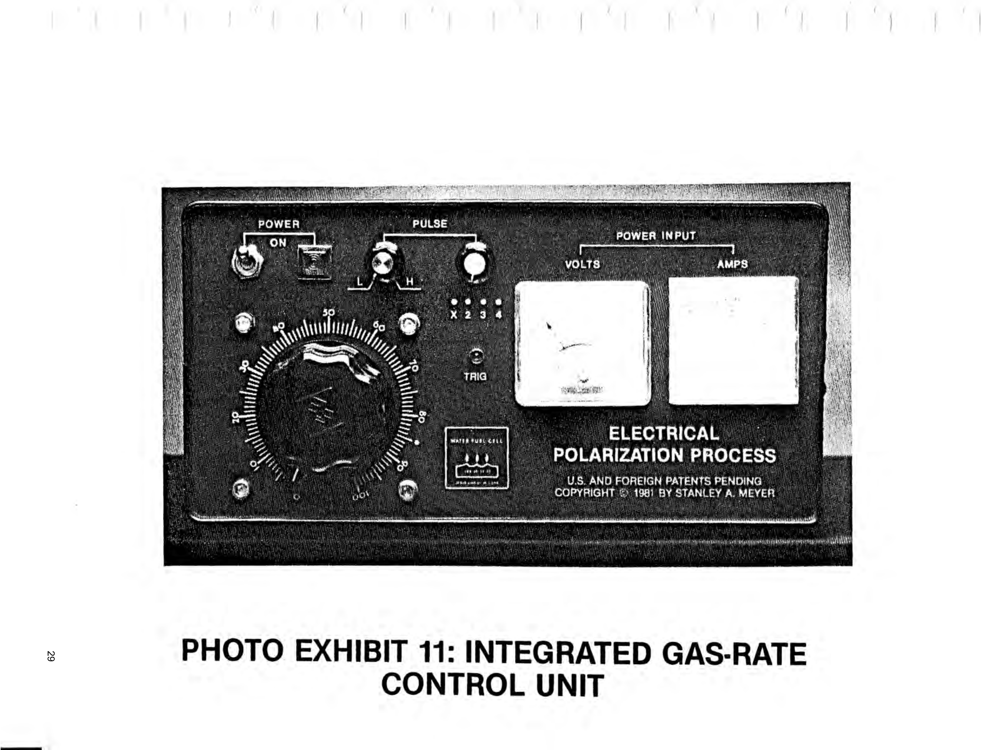
Page 29drawing sheetscan →
Page 30scan →
12vdc regulated
Power supply
Scr unipolar
Ated pulse-width
bieia oot CIRCUIT RESONANT CHARGING CHOKES
Fae (BIFILAR WOUND ABOUT INDUCTOR CORE)
Selectable decade counter (amp inhibitor circuit)
In/10 per satge
Triggering pulse circuit
Variable 110 vac
Transformer _— power input
Polarization process
U.8. and foreign patents prnoiws
COPYRIGHT +). 100! BY STANLEY A mar vt et
Photo exhibit 11a: electrical polarization process
RESONANT CHARGING CHOKE CIRCUIT (Fig. 9XA)
Copyright © 1981 by Stanley A. Meyer
Page 31scan →
Electrical Polarization Process 1M Se reper eT eTy beth ey a Nil
PRATT ST ne
Pc 9xb vpve card
Variable Pulse Triggering Circuit (Foil Side)
Page 32scan →
Electrical Polarization Process Bete y it
ADfawat igh
«he ite be iew)
Voltage Regulator Card PC 9XD (Component V il Side)
Voltage Regulator Card PC 9XD (Fo
Provenance
- Pages
- pages 21–32 of 140
- Binder
- WFC Project Binder 423-DA
- Method
- pdftoppm 300dpi + tesseract 5 (eng), orientation-corrected
- Source
- WFC International Independent Test-Evaluation Report (1995), scanned binder