

patent · US2460482A
Solar heat collector
1 February 1949
Text
Drawings
Page 1drawing sheetscan →
Page 2drawing sheetscan →
Page 3scan →
Patented Feb. 1, 1949
United states patent office 2,460,482
Solar heat collector
Charles Greeley Abbot, Washington, D. C.
Application February 20, 1945, Serial No. 578,806
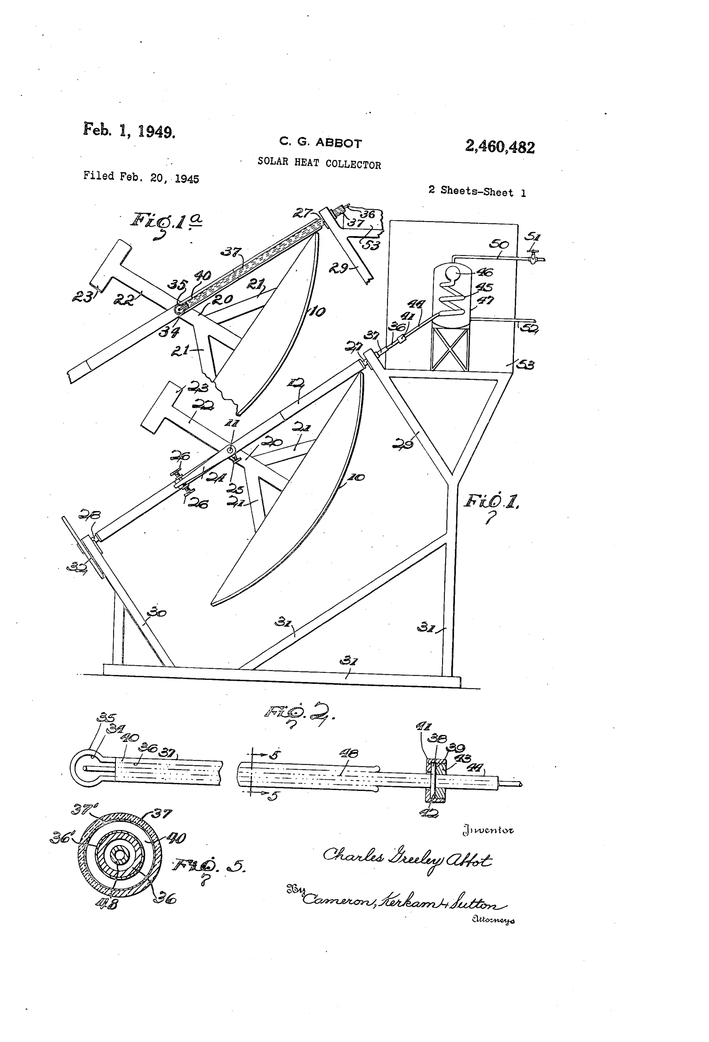
This invention relates to devices for collecting 2 heat from solar rays for storage and, while appli Fig. 1 is a side elevation, partly in section, of cable to the collection and storage of heat for a a device for collecting and storing solar heat in wide variety of purposes, will be disclosed with conformity with the present invention, the mirror particular reference to the collection and storage or reflector being shown somewhat diagramma of heat for use in a heat engine, because of par tically in the interest of simplicity. ticular utility in this field as will hereinafter Fig. la is a fragmentary view corresponding appear, although it is to be expressly understood to Fig. 1 to show the relationship of the heat that the invention is not restricted thereto. receiver to the mirror;
The primary object of this invention is to pro 0 Fig. 2 is an enlarged and partly sectionalized vide an improved device for collecting and storing diagrammatic view of the heat receiver of the solar heat under conditions of improved efficiency. present invention;
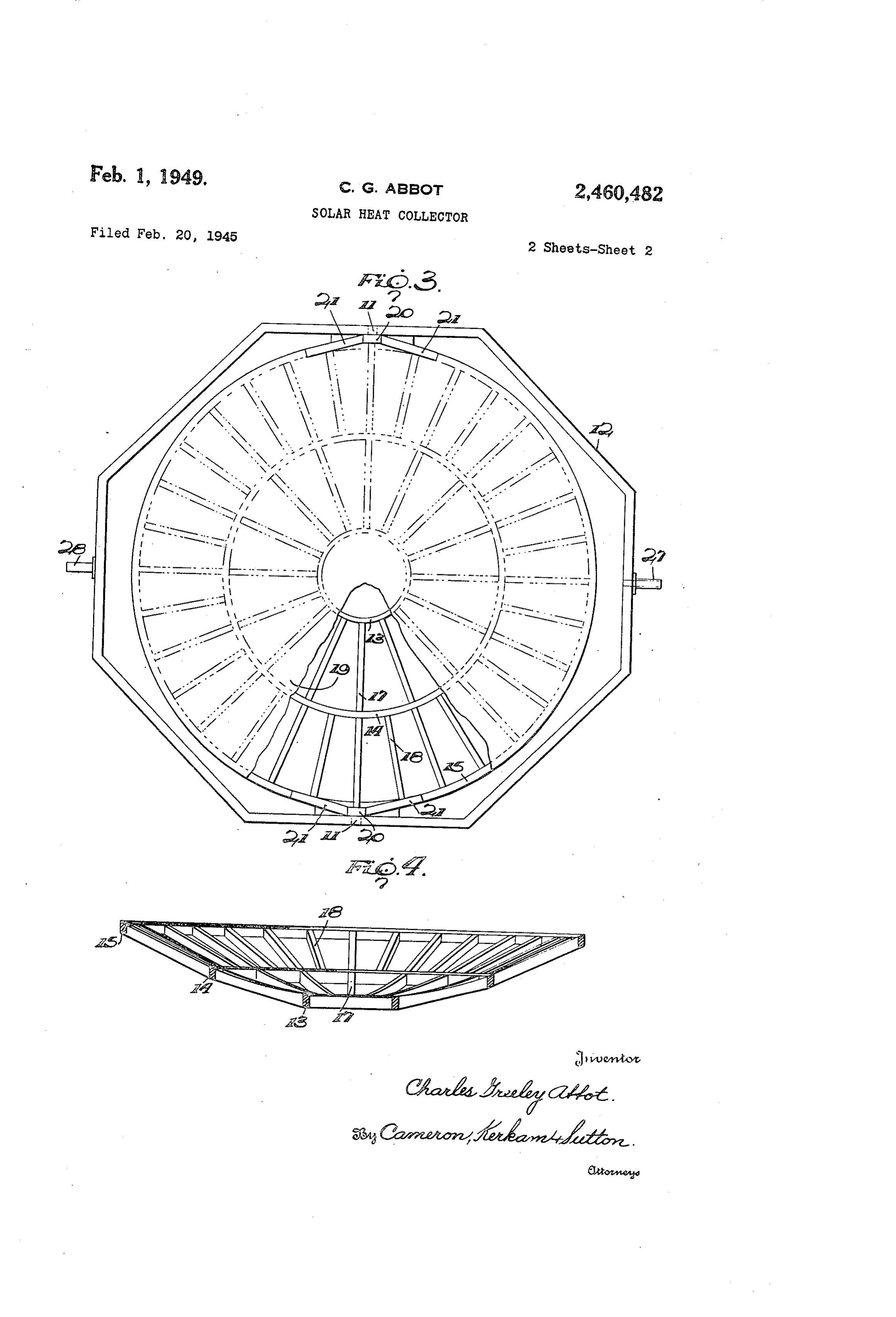
Another object of this invention is to provide Fig. 3 is an enlarged front view of the mirror an improved device for collecting and storing Surface and supporting fork with part of the reflecting solar heat characterized by low cost of produc 5 removed;
tion, operation and maintenance, Fig. 4 is a cross section through the frame of Another object of this invention is to provide the mirror; and an improved device for collecting and storing of Fig. 5 is an enlarged section on the line 5-5 Fig. 2, but not to scale.
solar heat which is of rugged and durable though relatively simple construction. 20 Before proceeding with a detailed description Another object of this invention is to provide of the embodiment of the invention illustrated on an improved device for collecting and St0ring the dra Wings, attention is directed to certain solar heat which provides for a continued supply fundamental propositions which will facilitate of stored heat during nights and cloudy days. an understanding of the detailed description Another object of this invention is to provide 25 hereinafter made.
an improved device for collecting and storing The simplest means of following the sun's solar heat that enables high efficiency operation diurnal path takes the form of an equatorial of a heat engine. mounting and aSSOciated driving means which Another object of this invention is to provide have long been perfected by astronomers, and an improved device for collecting and storing 30 it is to be understood that the mirror or reflec solar heat characterized by high efficiency in its tor of the present invention may utilize any preferred mounting and driving means of the absorption rayS.
and conservation of heat from solar character referred to. Whereas in some of my
Another object of this invention is to provide earlier patents, and in the patents of other in an improved device for collecting and storing ventors, for simplicity of production of large solar heat characterized by an improved construc 35 employed mirrors and for simplification of the mechanism for following the Sun, concave para tion of reflector for the sun's rays.
Another object of this invention is to provide bolic cylindrical mirrors have been used as ray an innproved device for collecting and storing collectors, with the mirror mounted With its axis solar heat characterized by an improved form of 40 parallel to the earth's axis, and provision has heat receivel'. been made for rotating such mirrors at 15 per Other objects will appear as the description of hour to follow the Sun's diurnal path, but neglect the invention proceeds. ing the sun's yearly march in declination, this The invention is capable of receiving a variety has been attended with two evils. First, the of mechanical expressions, one of which is illus 45 north and South ends of these mirrors have trated on the accompanying drawings, but it is been more or less ineffective at times of the year to be expressly understood that the drawings are partureother than the equinoxes and varying with de for purposes of illustration only, and are not to the mirrors from the equinoxes, and second, since be construed as a definition of the limits of the have been made long in proportion invention, reference being had to the appended : to their width, to diminish fractionally the loss claims for that purpose. thus occasioned, this has necessitated elongated heater elements extending substantially the full
Referring in detail to the accompanying draw length of the axis of the cylindrical mirror, with ings wherein like reference characters are used a consequent large heat loss by reason of their to designate corresponding parts in the several figures, excessive exposed areas. .
Where the means for collecting heat from solar
Page 4scan →
3 in any suitable way so as to incline its axis in a rays have been applied to the operation of a north South direction, and appropriate means heat engine, if high efficiency is to be obtained such as are known to those skilled in the art are and also if provision is made against failure of used for adjusting the mirror to conform with the source of heat at night or during cloudy the declination of the sun as it varies from day weather, several considerations must be kept to day in its north south march. As shown, the in view. First, the temperature of the engine trunnions f. carried by the fork 2 have pivotal fluid must be high in order that the expression engagement with uprights 20 disposed at dia T-T, metrically opposite sides of the mirror and illus T 0. trated as attached to the outermost zonal sepa rator 5, and said uprights may be provided with shall be as large a fraction as other considera any suitable braces 2 extending between the same tions permit. Second, losses of heat by radia and the Zonal separator 5 to give adequate tion, convection and conduction must be as low rigidity to the structure. One or both of said as is consistent with other considerations. To uprights 20 is extended beyond its trunnion f this end the surface for receiving the reflected as shown at 22 and provided with any suitable rays must be a minimum consistent with full counterweight 23. The means for adjusting the absorption of heat from the rays, while all losses mirror 0 on its trunnions may be of any suit of heat from the receiver surface and from the able construction such as commonly used in surfaces subjected to the medium for conveying astronomical instruments. As shown, an arm 24 collected heat to the engine fluid should be is aSSOciated with at least one of the trunnions reduced to a minimum. Third, by cutting losses l, Said arm surrounding the trunnion and carry of heat from the engine fluid itself to a minimum, ing a screw 25 for clamping said arm to the trun as by means of highly effective insulation, the nion in any suitable way as by means of a key. collected heat may be stored for relatively long 2 5 The other end of the arm 24 extends between a periods of time if the capacity of the reservoir be pair of adjusting screws 25 operating in nuts Sufficiently large. suitably mounted on the fork 2. A rough ad The present invention, as will appear from the justment of the location of the mirror iO may be ensuing description, provides an improved heat effected by first loosening the screw 25 and ap collecting and storage means that avoids defects proximately positioning the axis of the mirror f0, in prior proposals concerned with the collection after which the screw 25 may be tightened and and storage of heat from solar rays and affords accurate adjustments thereafter effected through highly efficient means for reflecting and collect manipulation of the screws 26, 26. Thereby the ing heat from said rays and transferring and axis of the paraboloid may be adjusted daily in storing said heat with a minimum of heat loss a north south direction to conform with the po so that it may be utilized with high efficiency and sition of the sun in its annual march. over long periods of time, such as nights and Fork 2 is provided with a second pair of trun cloudy days, when solar rays are unavailable. nions 27 and 28 in a plane at right angles to As shown on the accompanying drawings, the the trunnions, and said trunnions are mounted ray reflector takes the form of a circular para 4) by means of any suitable bearings, preferably bolic mirror 0 pivotally mounted on trunnions roller bearings, in supports 29 and 30 carried by in a closed octagonal frame 2, herein referred any suitable framework 3 f. Trunnion 28 carries to as the "fork' in conformity with astronomical any suitable means for rotating the fork 2 Sage. around the axis of the trunnions 27, 28 to cause While within certain aspects of this invention 45 the mirror fo to move through an angle of 15° the mirror O may be of any suitable construc per hour in following the diurnal movement of tion, I prefer to make the mirror, as shown more the Sun. Any suitable means may be employed particularly in Figs. 3 and 4, in the form of a for this purpose, such for example as shown in cradle of concave parabolic curvature composed my patents numbered 2,141,330 and 2,205,378, or of a plurality of circular zonal separators 3, 4 50 any other appropriate means known to those and 5 between which extend suitably spaced skilled in the art. For simplicity said means have ribs f and 8. Said cradle is preferably con not been shown in detail but are represented by structed of metal of low specific gravity, such a wheel 32 carried by the trunnion 28 and which for example as Duralumin. The reflector or mir may be driven by a worm, belt, etc., from an elec ror proper is composed of pluralities of sheets 55 tric motor, gravity motor, etc., appropriately of metal formed to the required curvature and Supported on or adjacent the frame 3. Suitably attached to said cradle, each zone be Disposed in the plane of the fork 2 so that the tween a pair of separators being filled with a mirror O may focus its rays upon a selected plurality of sheets suitably mounted on said ribs Spot thereon is a heat receiver shown somewhat with all the sheets in each zone similar to each 60 diagrammatically in enlarged detail in Figs. 2 other, but the sheets of one zone differing in and 5. In its preferred form said heat receiver shape and curvature from those of another zone. is composed of two concentric transparent globes When said series of Zonal sheets are attached to 34 and 35 whose centers lie in the axis of the the Zonal separators and ribs their size and cur paraboloid formed by the mirror 10, and also in Vature are such that together they constitute a 35 the axis of the trunnions 27, 28 and the axis of continuous Smooth parabolic surface 9 that is the circular in cross section in planes at right angles saidtrunnions paraboloid.
f at approximately the focus of
Said globes are formed inte to the axis of the reflector, i. e., the reflecting grally with or suitably sealed upon the ends of Surface is in the form of a paraboloid. The con
Cave surfaces of the constituent sheets are made 70 tube 37 opposite from the37,globe two coaxial tubes 36 and and the end of the 35 is sealed in highly reflecting by either a suitable Coating ma any suitable way upon the tube 36. The tubes terial, for example a film of rhodium, or by be ing composed of any suitable highly reflecting 36, 37 extend through the trunnion 27 which is material, for example an aluminum alloy or made hollow for this purpose, and beyond the seal the tube 36 has formed thereon or suitably preparation Such as “Alumilite.' 75 attached thereto a flange 38 which has a ground The mirror O is supported from the fork f2 5 flat surface 39. The chamber 40 between ele 6 ments 34, 36 and 35, 37 is airtight and is preferably 36 and globe 35, making it more difficult to main evacuated to a high degree of vacuum. So much tain the hermetic seal at this point. As a fur of at least one of the walls, and preferably both ther alternative construction the members 34, walls, defining this evacuated space 40 as are 35, 36 and 37 may be made of glass as heretofore not designed to be penetrated by rays focused by explained but metal members rendered highly the mirror O is plated, either interior'y or ex heat absorbing at the area, upon which the rays teriorly as preferred, with a reflecting metallic are focused may be inserted within the elements coating, for instance by the well known technique 34 and 36. This, however, sacrifices some of the known as 'silvering,' as shown at 36', 3' in Fig. 0 efficiency because the globe 34 will reflect sun's 5. The globes 33, 35 are transparent at least at rays from its inner surface to a greater extent their hemispheres directed toward the mirror than where said surface is one between glass. f0, and for simplicity may be transparent and Arochlor proaches that ofwhose glass. index of refraction ap throughout, but if preferred the outer hemi spheres of said globes may be provided with a re While I prefer to make the heat receiver with flecting metallic coating as in the case of the 5 a globular transparent portion, comparable to a tubes 36, 3. round bottom flask such as called by chemists a As will now be apparent to those skilled in the "matrass,' because the globular form is more ef art, the mirror C is adapted to transmit to the ficient as a receiver of the cone of rays reflected interior of the inner globe 34 rays focused by the 20 along the axis of the paraboloid, constituted by mirror O along its axis. Owing to the elimina the mirror 0, its is to be understood that, within tion of convection in the chamber 40 escape of the present invention and for greater facility of heat from the interior of globe 34 and its asso Construction, the receiver may take other forms, ciated tube 36 has been effectively hindered, and as the form of closed end tubes having suitable by plating to provide a reflecting coating over portiolus at or adjacent their closed ends on one or both of the opposed walls of the evacu 25 where the reflected rays are to be focused, ren ated chamber 40 not required to be transparent dered transparent or otherwise Suitably formed to receive the rays focused by the mirror f0, cool to transmit heat energy to the liquid in the inner ing by radiation outwardly from the globe 34 Vacuum-jacketed tube with other surfaces plated and associated tube 36 is nearly eliminated. to minimize radiation as above described. 30 The coil 45 with its expansion chamber 46 is
Attached at flange 38 in any suitable way, as supported in the chamber 47 in any suitable way, by screw collar 4? and washer 42, is a flange 43 said chamber being provided with strong rigid carried by tube 44, which may be made of metal walls capable of withstanding the pressure to and which through the joint thereby effected is be generated therein. Chamber 47 contains any hermetically sealed to the end of the tube 36.
Tube 44 at its opposite end communicates with be suitable fluid, as Water for example, that may a coil 45 having at its opposite end an expan vaporized if a heat engine or other instru sion chamber 46 and mounted within a liquid though mentality using vapor is to be employed, al containing chamber 4 as hereinafter referred as above indicated the present invention to. The System composed of globe 34, tube 36, 4) is not limited to utilizing the heat, stored in the tube 44 and coil 85 with its expansion chamber fluid in the chamber 47 in a heat engine, but 46 is substantially filled, with only such space Said fluid may be such as is Suitable for utilizing left as is requisite for expansion, with a liquid the stored heat in a variety of other ways. which is highly absorbent for sun rays and pref Chamber 47 has an outlet conduit 50, in which erably of high boiling point. Any suitable liquid may be disposed a suitable cock 5, for convey may be used for this purpose, such as one of the ing the heated fluid to its place of use, and a chlorinated dyphenols, for example “Arochlor' return pipe for the fluid is indicated at 52. The produced by the Monsanto Chemical Company chamber 47 is enclosed in efficient insulation 53 having a boiling point on the order of 355° C. sufficient to prevent loss of heat at any consider and of dark color. This liquid is preferably made in able rate, whereby heat imparted to the fluid more completely heat absorbent by suspending or chamber 47 may be conserved for use at night during cloudy periods. The unit including therein black.
a suitable quantity of finely divided lamp the chamber 47 and its insulation 53 have been
Extending axially through the tubes 36 and 44 shown as supported from the frame 3 but, as is a tube 48 that may be made of metal and which will be apparent to those skilled in the art, said reaches nearly to the bottom of the globe 34 at unit may be supported in any other suitable way One end and connects with the coil 45 at its other and disposed at any other suitable location. For end, said tube 48 being open at both ends. Tube the protection of the heat receiver as above de 48 thus constitutes a return tube for the liquid scribed the same may be provided with any suit which is heated in the globe 34 and, arising 6 able enclosure of metal or the like, omitted from through the tubes 36 and 44 to the coil 45, ex Fig. 2 in the interest of illustrating the parts changes its heat with the fluid in the chamber. that would be enclosed thereby, said enclosure 4T, whereupon the cooler liquid in the coil 45 suitably exposing the proper portion of the heat returns through tube 48 to the globe 34. Thus a receiver to the reflected rays, and passing through gravity circulation is maintained between the (5 the trunnion 27 and being supported from the support, 29 in any suitable way.
coil 45 and the globe 34.
As an alternative construction globe 34 and In operation the mirror 0 is adjusted So as tube 36 may be made of metal rendered highly to concentrate the reflected solar rays upon the -absorbent of solar rays by suitably coating the globes 34, 36, and these rays, passing through surface of globe 34 onto which said rays are said globes, heat the absorbent liquid in globe focused with lampblack or other suitable heat 34 and set up the circulation heretofore described absorbing material. This construction is more whereby the absorbed heat is transmitted to the efficient in that it eliminates reflection from the coil 45 to heat the fluid in chamber 4. Escape globe 34 but introduces the disadvantage of dis cf heat from the chamber 47 is prevented by the similar materials at the seal between the tube insulation 53, and the fluid in said chamber can be raised to a suitable temperature, well above
Page 6scan →
7 calories per minute are the equivalent of one the boiling point of water, whereby high tem horsepower, this figure shows that a mirror of perature vapor is available for use at any time 154 feet in diameter may suffice for a five horse during the day or night. power solar heat engine plant. By concentrating Some of the advantages of the present inven a number of five horsepower solar units as de tion will appear from the following considera scribed and connecting them to deliver heat to tions. A highly reflecting metal mirror in the a common reservoir, solar rays may be utilized form of a paraboloid may reflect 82% of the solar for building considerable potential power at rays and the paraboloid may be sufficiently accu minimum expense. At the same time each unit rate to focus this percentage of the rays On a 10 may be kept small enough so that the difficulties cross section whose diameter does not exceed 4 which would be introduced by wind if larger mir inch for each one foot of external radius of the ror surfaces were employed are avoided. Particu mirror. Because of this high efficiency in focusing larly in relatively cloudless regions a solar heat the reflected rays within a small area. I prefer to engine unit as herein disclosed may thus compete make the mirror 0 in the form of a paraboloid favorably with small power units using power as explained, but as will be apparent to those 5 derived from coal or hydraulic sources, while by skilled in the art the mirror O may depart Sonne combining units as hereinbefore mentioned larger what from a paraboloid with some loss in eff sources of power may be made readily available ciency while still retaining some of the advan at low cost.
tages of the present invention. While the embodinent of the invention illus Assume that the mirror O has a diameter of 20 trated on the drawings has been described with 154 feet. Experiments in many lands have considerable particularity, it is to be expressly shown that sun rays falling on a mirror oriented understood that the invention is not restricted at right angles to the beam may be assumed con thereto, as the same is capable of receiving a servatively to contain energy equal to 1.2 calories variety of mechanical expressions, some of which per square centimeter per minute throughout an will now readily suggest themselves to those skill average cloudless day in moderate latitudes. ed in the art, while changes may be made in the Where extraordinarily favorable conditions exist details of construction and in the arrangement this figure may reach 1.4 calories or even higher. and proportion of parts, and certain features may A mirror of 154 feet diameter will therefore re 30 be used with other features, without departing ceive an average of about 203,000 calories per from the spirit of this invention, Reference is minute or more through average cloudless dayS, therefore to be had to the appended claims for and if the globe 34 is made three inches in a definition of this invention. diameter it will catch substantially all of the What is claimed is:
rays reflected from the mirror f0. Of the rays i. In a solar heat collector, in combination with reaching the globe 35, about 92% will be trans a paraboloidal mirror, a heat receiver including mitted to the globe 34. Of the rays reaching the a globe of material highly transmissible to heat globe 34, about 95% will be transmitted through rays disposed at the focus of Said mirror and a its transparent wall and be absorbed by the black tube communicating therewith, said globe and liquid. tube being filled with a highly ray-absorbing high If the collection of heat at the reservoir 47 40 boiling-point liquid, and a second globe and com is continued until the temperature of the fluid municating tube Surrounding but Spaced from therein reaches 300° C., and assuming that it is said first globe and tube, said second globe be used in a heat engine operating between 300° C. ing formed of transparent material, Said Second and 20° C., the thermodynamic quantity tube being sealed hermetically to said first tube at the end of said Second tube opposite its globe and the space between said globes and tubes be
The loss of heat may be neglected except where ing highly evacuated, said tubes having their opposed walls plated with reflecting metal, and the transparent globes 34, 36 lose heat by radia 50 a heat exchanger in communication with said tion and thence by convection. The loss of heat first-named tube.
from a perfect radiator at 300° C. to absolute 2. In a solar heat collector, in combination with zero is 8.888 calories per square centimeter per a paraboloidal mirror, a heat receiver including a minute, but the globe 36 to which the globe 34 glass globe at the focus of said mirror and a glass radiates may be assumed to be at 36 C. It will tube communicating therewith, said globe and therefore reradiate upon globe 34 at the rate of 0.76 calory per square centimeter per minute, so tube being filled with a highly ray-absorbing high boiling-point liquid and a transparent vacuum that the figure for the loss of heat from globe jacket surrounding said globe and tube, the inte 34 is reduced to 8.12 calories. The surface of rior of said vacuum jacket surrounding said tube globe 34 is 176 square centimeters and hence if it is a radiator throughout its surface the total 60 being film, provided with a highly reflecting metal and a heat exchanger in communication heat loss per minute is only 1430 calories. This with said first named tube. is slightly less than 1% of the heat absorbed 3. In a Solar cheat collector, a heat receiver in by the globe 34. cluding a globe of material which is highly trans An excellent heat engine may have as high missible to heat rays and a tube communicat as 75% efficiency of the so-called perfect engine. ing therewith, said globe and tube being filled Combining the preceding figures of efficiency ' With a highly ray-absorbing high boiling-point there is thus the capacity for conversion into liquid, a second globe and communicating tube mechanical work of the following fraction of the surrounding but spaced from said first globe and solar radiant energy which strikes the mirror:
70 tube, Said second globe being formed of trans 0.82x0.92x0.95X 0.99X0.49X0.75=0.26 or 26% parent material, said second tube being sealed hernetically to said first tube at the end of Said
Thus while 203,000 calories per minute are inter Second tube opposite its globe and the space be cepted by the mirror, 52,780 calories may be con tween said globes and tubes being highly evacu verted into mechanical Work by a construction 75 ated, said tubes having their opposed walls plated conforming to the present invention. As 10,164 7 with reflecting metal, a heat exchanger in comr spectively, to said plated 10 munication with said first-named tube, a return and unplated portions tube in said first-named tube and in communi of said primary glass tube, said secondary glass cation with said heat exchanger for promoting tube tube hernetically sealed to said primary glass gravity circulation of said liquid, a ray reflector at the plated end thereof, the space between substantially in the form of a paraboloid, and highlyprimary said and secondary glass tubes being evacuated, a hermetically sealed primary means for mounting said heat collector with said receptacle for liquid in canalized communica globes substantially at the focus of said reflector. tion with said primary glass tube, an open-ended 4. In a Solar heat collector, a heat receiver tube within said primary glass tube, extending including a glass tube having a closed end with O approximately from the non-plated portion there the portion thereof adjacent said end transparent of to within said primary receptacle for liquid, a to heat rays, said tube being surrounded by a highly ray-absorbing, high boiling-point liquid transparent vacuum jacket, Said tube containing a highly ray-absorbing high boiling-point liquid, receptacle, a heat-insulatedtube within said primary glass and said primary the interior of said vacuum jacket elsewhere 15 for liquid surrounding said secondary primary receptacle receptacle, than opposite the transparent portion of Said first the liquid contained in said secondary receptacle named tube having a highly reflecting metal film, immersing said primary receptacle, the whole a heat exchanger in communication with said combination adapted to collect heat from solar first-named tube, a return tube in said first rays and transfer said heat by circulation of said named tube and in communication with said heat high-boiling liquid for storage in the liquid within exchanger for promoting gravity circulation of 20 Said secondary receptacle.
said liquid, a ray reflector Substantially in the CHARLES GREELEY ABBOT, form of a paraboloid, and means for mounting said heat collector with said transparent portion REFERENCES CTED of said first named tube Substantially at the focus 25 of said reflector. The following references are of record in the 5. In a solar heat collector, a heat receiver in file of this patent:
cluding a glass globe and a glass tube communi UNITED STATES PATENTS cating therewith, said globe and tube being filled Number Name Date with a highly ray-absorbing high boiling-point 30 liquid and a transparent vacuum jacket sur 73,355 Marshall ----------- Jan. 14, 1868 rounding said globe and tube, the interior of 507,999 Davis --------------- Nov. 7, 1893 Said vacuum jacket surrounding said tube be 787,145 Brown ------------- Apr. 11, 1905 ing provided with a highly reflecting metal film, 797,891 Himalaya ---------- Aug. 22, 1905 a heat exchanger in communication with said 820,127 Pope --------------- May 8, 1906 first-named tube, a return tube in said first 888,054. Aschenbrenner ------ May 19, 1908 named tube and in communication with said heat 922,174 Lyman ------------- May 18, 1909 exchanger for promoting gravity circulation of 980,505 Emmet ------------ Jan. 3, 1911. said liquid, a ray reflector substantially in the 1,068,650 Harrison ----------- July 29, 1913 form of a paraboloid, and means for mounting 1,242,511 Bailey ------------- Oct. 9, 1917 said heat collector with said globe substantially at 40 1832,248 the focus of said reflector.
6. In a solar heat collector a paraboloidal mir 1951,403 Goddard ----------- Mar. 20, 1934 ror, a mounting for said mirror, Said mounting 2,119,009 Elias -------------- May 31, 1938 adapted to maintain the focus of solar rays re 45 2,247,830 flected from Said mirror upon a fixed spot, a pri Abbot --------------- July 1, 1941 mary glass tube exteriorly metal-plated over a FOREIGN PATENTS major portion of its length, but with a short un Number Country Date plated portion, said mounting adapted to main tain said unplated portion of said primary tube 50 551,598 France ------------- Jan. 11, 1923 in the focus of said mirror, a secondary glass 556,333 France ------------- Apr. 11, 1923 tube spaced exteriorly from said primary glass 635,283 France ------------- Dec. 27, 1927 tube, said Secondary glass tube having inte 824,726 France ------------- Nov. 18, 1937 riorly-plate and unplated portions opposite, re
Provenance
- Collection
- Patents citing this work
- Pages
- 7
- Method
- pdftotext (the PDF's own text layer) + pdftoppm 300dpi page scans
- Patent office record
- patents.google.com →
- Source
- Google Patents citing-documents table
- Assignee
- Abbot Charles Greeley
- Published
- 1949-02-01
- Transcribed from
- patentimages.storage.googleapis.com →