

patent · US4245620A
Solar heat collector
20 January 1981
Text
Page 1scan →
United States Patent (19)
Heinemann
(54) solar heat collector
75 Inventor: Klaus W. Heinemann, Sunnyvale,
Calif.
73 Assignee: Alten Corporation, Mountain View,
Calif.
51 Int. C. ..... - -- - - - -- - - - - - - - - - - - - - - - - F24, 3/02 52 U.S. C. ..................................... 126/447; 126/448 i,338,644 4/920 Arthur et al. ........................ 126/271 3,089,670 5/1963 Johnson ....... ... 26/441 3,310,102 3/1967 Trombe - -- - - - - - - - -- - - - --- - 26/45 3,981,294 9/1976 Deminet et al. . ... 126/27 4,015,582 4/1977 Liu et al. .............................. 126/27 4,015,583 4/1977 Laing ....... ... 126/27 4,078,548 3/1978 Kapany --- 126/441 4,084,574 4/1978 Golay ............... ... 26/27 4,085,667 4/1978 Christianson ........ ... 126/270 4,091,793 5/1978. Hermann et al. ... ... 26/44
4,114,597 9/1978 Erb ....................................... 165/i72 4,116,224 9/1978 Lupkas ................................. 26/27
Foreign patent documents
Other publications
V. D. Bevilland H. Brandt, “A Solar Energy Collector for Heating Air”, Solar Energy, vol. 12, pp. 19-29,
Pergamon Press, England, 1968.
Primary Examiner-James C. Yeung
Attorney, Agent, or Firm-Limbach, Limbach & Sutto
A solar heat collector panel having an absorber plate with fins as part thereof to reduce convection air cur rents and heat loss from the panel. A screen disposed above a collector plate also reduces the undesired con vection air currents. A fluid carrying pipe is attached to the collector plate by snapping into channels therein after a sealer material has been placed in the channel.
9 Claims, 6 Drawing Figures
Drawings
Page 2drawing sheetscan →
Page 3drawing sheetscan →
Page 4scan →
a heat collector plate that omits the fins, is a screen
SOLAR HEAT COLLECTOR positioned between the heat collector and glazing (if any). The screen also functions to restrict travel of the
BACKGROUND OF THE INVENTION natural convection currents away from the heat absorb This invention relates generally to an improved solar 5 ing collector plate. The efficiency of the solar collector heat collector panel and methods of manufacturing such is thus In increased.
constructing the solar panel, the heat absorbing panels.
Solar heat collectors are becoming widely used as collector plate is preferably made of extruded aluminum sources of energy for heating swimming pools, building with the carrier for the heat transfer medium, which is space and usable hot water. The collector, placed to 10 usually water, being a copper pipe. Channels are formed receive maximum exposure to the sun, generally in in the collector plate into which the copper pipe nests. cludes a flat absorber plate with a heat absorbing sur The opening to the channel is made slightly smaller face and ducts attached thereto for carrying fluid. The than the outside diameter of the pipe and the collector fluid is heated from the heat absorbing surface and then 15 plate is made resilient enough so that the pipe can be transferred to a heat storage reservoir. Liquid or air can snapped into place and retained without further fasten be utilized as the heat transfer medium. ing. Before urging the copper pipe into the channel, a These main components of a solar heat collector are bead of water impervious sealing material, such as sili generally located inside an enclosure having a light con rubber, is placed in the bottom of the channel. transparent glazing spaced a distance from the black 20 When the copper pipe is then positioned in the channel, absorbing surface. The purpose of the cover is to pre the sealant spreads out to fill in all voids between the vent heated air from the vicinity of the absorber from copper pipe and the aluminum channel which aids both escaping the collector and being lost to the atmosphere. in heat transfer and in preventing corrosion. It has been a constant goal in solar collector design to Additional objects, advantages and features of the improve their efficiency; that is, to improve the propor 25 various aspects of the present invention are given in the tion of incident sunlight energy that is converted into following detailed description of its preferred embodi usable heat that may be transported to a location where ments, which should be taken in conjunction with the it is desired. accompanying drawings.
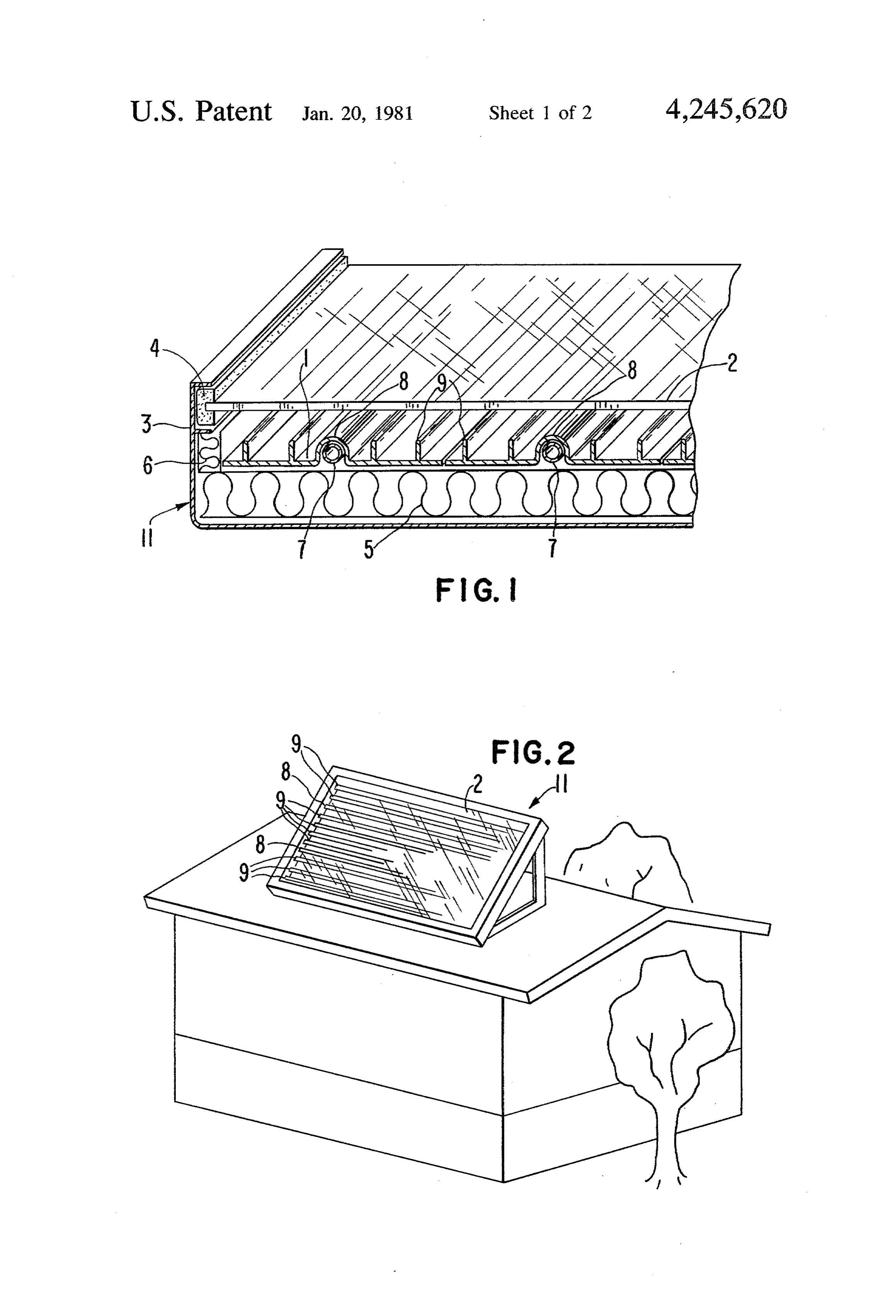
Even with the use of a giazing in a solar collector, its collection efficiency (defined as a ratio of actually col BRIEF DESCRIPTION OF THE DRAWINGS lected and primary incident energy) is generally signifi 30 FIG. 1 is a partially cut away view of an embodiment cantly less than unity. This is due, in part, to losses of a solar collector panel utilizing various aspects of the between the heat transfer medium and the lower ambi ent temperature of the surroundings. Such losses are present invention;
principally due to air convection in front of the heat ofFIG. 2 illustrates generally one particular orientation the solar panel according to FIG. 1;
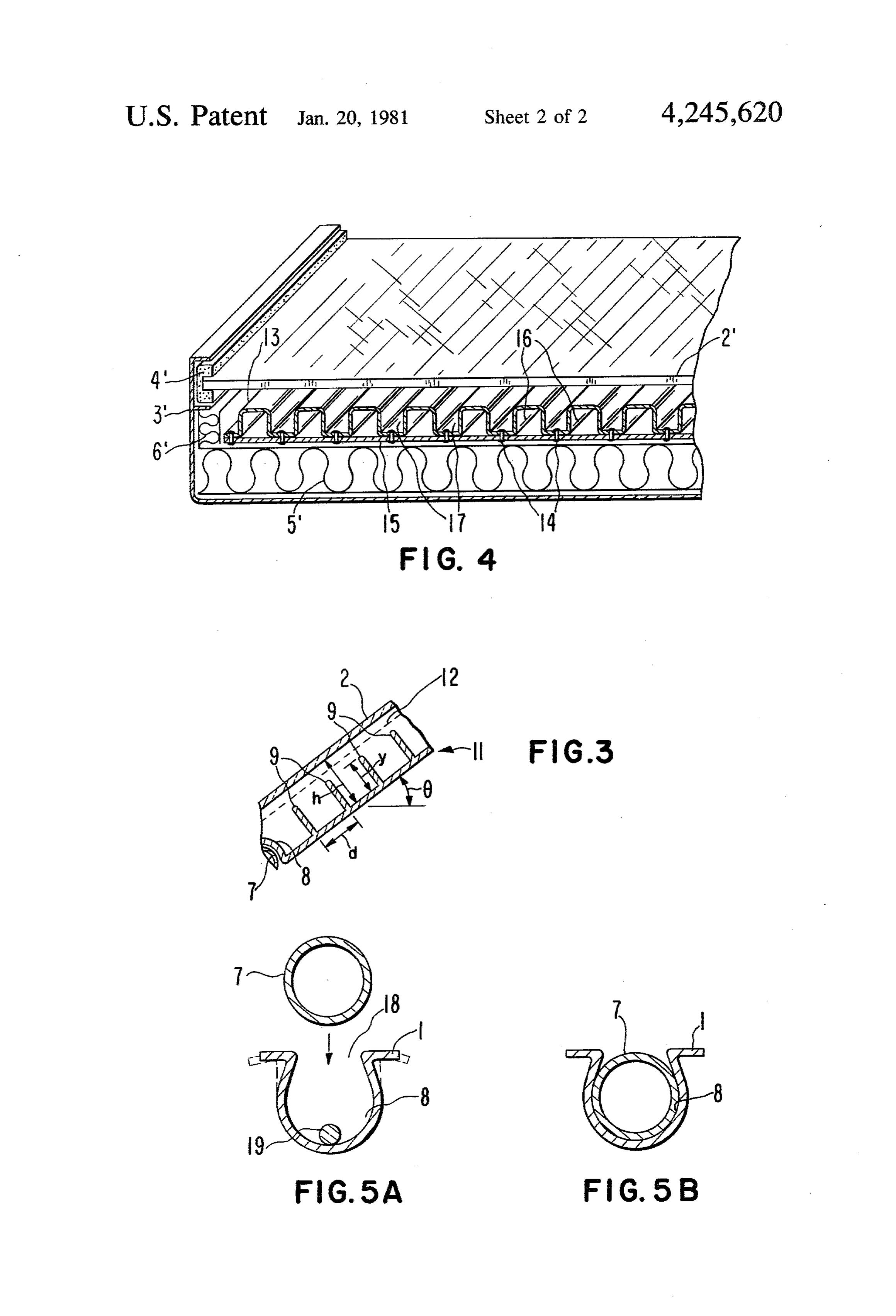
absorber which carrier heat away from it to the atmo 35 FIG.
sphere. In the case of solar heat collectors that have no the solar3panel illustrates schematically a sectional view of illustrated in FIGS. 1 and 2;
transparent cover (unglazed), convection currents con FIG. 4 is a partially cut away view of another em stantly replace the warm heated air adjacent the ab bodiment of a solar panel utilizing various aspects of the sorber with cooler anbient air which is then, in turn, present invention; and heated by the absorber and lost. Where the collector is covered by a light transparent medium (glazed), the to FIGS. 5A and 5B illustrate the technique according the present invention of assemblying the solar panel convection currents are still present in existing solar illustrated in FIG. 1.
collectors and result in transferring heat from the ab sorber to the cooler glazing. The glazing then transmits DESCRIPTION OF THE PREFERRED this heat by direct conduction to the surrounding atmo 45 EMBODEMENTS sphere. Such heat osses are a particular problem for Referring to FIG. 1, a solar heat collector is illus solar domestic water heating, space heating and air trated conditioning where the temperature of the fluid transfer lector tothattheutilizes liquid to transfer heat from the col point of use. An absorber plate 1 is prefera medium is maintained a great deal above the ambient bly made from extruded aluminum. The absorber plate temperature of the surroundings. SO
Therefore, it is a principal object of the present inven 1radiant is painted on its top surface for receiving an absorbing energy through a glazing 2, preferably made of tion to provide a solar heat collector construction that clear glass. The absorber plate 1 and the glazing 2 ex results in a higher efficiency utilization of the solar tend in a two dimensional area within a solid metal energy incident upon it. frame 3 that is generally of a rectangular shape. The It is another object of the present invention to pro 55 vide an improved technique for attaching a fluid heat glazing 2 is held into the frame 3 by a glazing bead 4. A transfer medium carrier to a heat absorber plate. layer of insulation 5 is positioned beneath the absorber plate 1 and the bottom of the frame 3 to minimize heat
SUMMARY OF THE INVENTION losses through the rear of the solar collector plate. Insu These and additional objects are accomplished by the lation 6 is also provided around the edge of the absorber various aspects of the present invention, wherein plate 1.
briefly, a generally flat heat absorber plate is provided A fluid carrying round pipe 7 is carried in a channel as an integral part thereof with upstanding straight fins 8 formed within the collector plate 1. A plurality of extending in one direction thereacross. The fins break such channels and pipes extend across the absorber up natural convection currents within the collector so 65 plate 1 in only one direction in parallel rows. The rows that a reduced amount of heated air either escapes from of pipe 7 are then connected at their ends to provide a an unglazed collector or contacts the glazing of a glazed single path for fluid that runs back and forth across the collector. Utilized in conjunction with the fins, or with absorber plate from a single fluid input to a single fluid 5 output. The rows of pipe 7 are preferably formed from parallel air carrying channels 16. The channels are pref a single continuous pipe that is bent at its ends to form erably connected at the ends of the solar collector (not the pipe in a serpentine shape. shown) in a manner to provide a single air channel that In between the elongated cavities 8 are disposed sev traverses back and forth across the solar collector and eral elongated fins 9 that rise from the generally flat 5 has a single cool air input and a single hot air output. base plate region of the absorber 1 as an integral con The channels 16 are formed from equally spaced square struction. These fins have a principal purpose of reduc undulations of the absorber cover plate 13. Spaces 17 ing the natural conduction currents that tend, in an between the hot air carrying channels 16 are made to actual solar installation, to carry heated air from the top have dimensions within the range discussed previously surface of the absorber plate 1 to the glazing 2 where 10 with respect to FIG. 3 for fins in order to reduce the the heat can be lost to the surroundings by convection heat loss through the glazing by convection air cur through the glazing 2. rents. Similarly, a screen (not shown) may be disposed The elements described with respect to FIG. 1 form between the top of the absorber plate 13 and the under a solar panel 11 which is installed on a building rooftop side of the glazing 2", in a manner discussed with respect as shown in FIG. 2 in a typical application. The solar 15 to the screen 2 of FIG. 3.
collector 11 is tilted upward with respect to the building Referring to FIGS.5A and 5B, a preferred construc roof. in order to maximize the solar energy that falls tion and method of forming a portion of the solar collec upon its two dimensional surface. The collector 11 is tor of FIGS. 1-3 is illustrated. Referring to FIG. 5A, oriented with its channels 8 and fins 9 having their long the channel 8 formed from the underside of the absorber dimension substantially horizontal. 20 plate 1 has an opening 18 thereinto that has a width that The preferred fin structure of the collector 11 will is slightly less than the outside diameter of the pipe 7. now be described with respect to the sectional view of The material and thickness of the absorber plate 1 is FIG. 3. The angle 6 is the angle that the flat portion of chosen so that the pipe 7 can be forced through the the absorber plate 1 makes with the horizontal in an opening 18 into the channel 8 by spreading apart the actual installation. This angle is usually about 45. The 25 sides of the opening 18 momentarily. Before forcing the fins 9, making a right angle with the base of the ab pipe 7 into the channel 8, however, a bead of water sorber plate 1, are most conveniently of uniform height impervious moldable material 19, such as silicon rubber, and spacing. It has been found that the dimensions 'd', is desposited along the length of the channel 8. Enough “h” and “y” as illustrated in FIG. 3 are preferably of the material 19 is used so that when the pipe 7 is within the following ranges: 30 inserted into the channel 8 it spreads around the inter d: from 0.5 inch to 3.0 inch face between the outside of the pipe 7 and the walls of h: from 0.5 inch to 1.5 inch the channel 8 to fill all voids. This sealing operation has y: from 0.25 inch to 1.0 inch two purposes. First, the heat transfer between the ab Similarly, it has been found that the optimum ratio of sorber plate 1 and the liquid carrying pipe 7 is made the dimension "h' to the dimension "d' is approxi- 35 better if all of the air pockets that might otherwise exist mately 1.0. The optimum ratio of the dimension “y” to between the two parts in the channel 8 are eliminated. the dimension "h' is in the range of 0.5 inch to 0.75 Second, the use of such a sealer prevents moisture from inch. The optimum dimensions "d' and "y' are each getting inbetween the pipe 7 and the walls of the chan approximately 1 inch for a solar collector of general nel 8 and this prevents electrolysis between the pipe 7, application. preferably made of copper, and the absorber plate 1, It can be seen from FIG. 3 that the fins 9 restrict the preferably made of aluminum. In order to further re natural convection of warm air from the base of the duce the possibility of electrolysis, the pipe 7 is prefera server plate 1 particularly around the fluid carrying bly painted on the outside with a black insulating paint pipes 7, to the glazing 2. Heat loss is thus significantly prior to its being inserted within the channel 8. Such reduced. If the ranges of dimensional parameters stated 45 painting acts to reduce the extent of the area of contact above are not followed, the fins are likely not to be between the copper pipe 7 and the aluminum 1. effective to inhibit these undesired convection currents. Although the various aspects of the present invention FIG. 3 also shows an optional screen 12 extending have been described with respect to specific embodi over the entire surface area of the solar collector and ments and examples thereof, it will be understood that suspended between the top of the ribs 9 and the under 50 the invention is entitled to protection within the full side of the glazing 2. The screen 12 can be selected from scope of the appended claims.
ordinary wire mesh screen, clear plastic fiber screen and I claim:
similar products. It has been found that the existence of 1. A solar energy collecting panel, comprising: the screen 12 also has an inhibiting effect upon the con a two dimensional heat absorber having a substan vection currents that tend to rise from the absorber 55 tially flat bottom, plate 1 to the glazing 2. Screen 12 is drawn taught and means in heat contact relationship with said absorber fastened around the edges of the frame 3 (not shown.) for providing a plurality of fluid conduits there The screen 12 may be used with the fins 9 as shown in across in one direction and substantially parallel to FIG. 3 or may be beneficially utilized even if the fins 9 one another, are not used. 60 an enclosure for said absorber and said fluid path FIG. 4 illustrates a modification of the solar collector means, said enclosure including a heat radiation panel described above with respect to FIGS. 1-3. transparent glazing positioned thereacross in a Equivalent components are given the same reference manner to keep air from escaping from above said characters in FIG. 4 with a prime () added thereto. The absorber, solar collector panel of FIG. 4 is adapted for utilizing 65 said absorber including a plurality of fins rising from air as the heat carrying fluid medium. An absorber plate the substantially flat bottom portion and extending 13 is attached by connectors 14 to an absorber back in said one direction along its length substantially plate 15. The result is the formation of a plurality of parallel to one another, the spacing of said fins 6 being substantially within the range of 0.5 inch to said absorber including a plurality of fins rising from 3.0 inch, the height of each fin being substantially a flat bottom portion in an integral construction in the range of 0.25 inch to 1.0 inch and the distance and extending in said one direction along its length between the flat bottom portion of said absorber 5 parallel to one another, a ratio of the height of each and said glazing being substantially within the of said fins to the distance from the absorber bot range of 0.5 inch to 1.5 inch, whereby undesired tom to the glazing lies substantially within a range convection air currents within said enclosure are of 0.5 to 0.75, and a ratio of a distance between the minimized and the efficiency of the collector in absorber botton and the glazing to the distance between fins along the absorber flat bottom is sub creased. 10 stantially equal to one, and 2. The solar energy collecting panel according to means for mounting the collecting panel with its claim 1 wherein the ratio of distance between the ab absorber at a finite angle with horizontal but with sorber and the glazing to the distance between fins said fins extending substantially horizontally, along the absorber flat bottom is substantially equal to whereby undersired convection air currents within one, and further wherein the ratio of the fin height to 15 said enclosure are minimized and the efficiency of the distance from the absorber bottom to the glazing lies the collector increased.
substantially within a range of 0.5 to 0.75. 8. The solar energy collecting panel installation ac 3. The solar energy collecting panel according to cording to claim 7, wherein said finite angle is substan claim 1 wherein the spacing between said fins and the tially forty-five degrees.
height of said fins are each substantially one inch. 20 9. A solar energy collecting panel, comprising: 4. The solar energy collecting panel according to a two-dimensional heat absorber having a substan claim 1 which additionally comprises a mesh screen tially flat bottom, layer disposed between said glazing in the top of said means in heat contact relationship with said absorber fins. for providing a plurality of fluid conduits there 5. The solar energy collecting panel according to 25 across in one direction and substantially parallel claim 1 wherein the distance between the flat bottom with one another, and portion of said absorber and said glazing is substantially an enclosure for said absorber and said fluid path means, said enclosure including a substantially flat equal to the spacing between said fins. layer of heat radiation transparent glazing posi 6. The solar energy collecting panel according to 30 tioned thereacross in a manner to keep air from claim 1, wherein the ratio of the fin height to the dis escaping above said absorber, said absorber includ tance from the absorber bottom to the glazing lies sub ing a plurality of fins rising from the substantially stantially within a range of 0.5 to 0.75. flat bottom portion of the absorber toward said 7. A solar energy collecting panel installation, com glazing and extending in said one direction across prising: 35 the absorber substantially parallel to one another, a a two dimensional heat absorber, distance between the absorber and the glazing means in heat contact relationship with said absorber being substantially equal to a spacing between said for providing a plurality of fluid conduits there fins, and further wherein the ratio of the fin height across in one direction, and to the distance from the absorber bottom to the an enclosure for said absorber and said fluid path 40 glazing lies substantially within a range of 0.5 to means, said enclosure including a substantially flat 0.75 whereby undesired convection air currents heat radiation transparent glazing positioned there within said enclosure are minimized and the effi across in a manner to keep air from escaping from ciency of the collector increased.
Provenance
- Collection
- Patents citing this work
- Pages
- 6
- Method
- pdftotext (the PDF's own text layer) + pdftoppm 300dpi page scans
- Patent office record
- patents.google.com →
- Source
- Google Patents citing-documents table
- Assignee
- Alten Corporation
- Published
- 1981-01-20
- Transcribed from
- patentimages.storage.googleapis.com →