

patent · US4513731A
Solar heat collector
30 April 1985
Text
Page 1scan →
United States Patent (19)
Campbell
54 solar heat collector
76) Inventor: Willis R. Campbell, R.D. #3, Box. 58, Ephrata, Pa. 17522
5 1) Int. C.3 s so so so as a a 4 a e o so o o - F24 9: 52 U.S. C. sa e s - a v 8s a www 126/432; E.
2,213,894 9/1940 Barry .............................. 26/443 X 2,402,326 6/1946 Harkness ............................. 126/446 3,927,659 12/1975 Blake et al. ... ... 126/450 X 4,030,478 6/1977 Beaver ................................ 126/448
4,116,223 9/1978 Vasilantone ........................ 126/435 4,212,290 6/1980 Warnken ....... ... 126/446X 4,220,140 9/1980 Francia ..... ... 26/450X 4,249,515 2/1981 Page ...... ... 126/47 X 4,289,119 9/1981 Meyer ................................. 126/440
4,341,204 7/1982 Bloxsom .............................. 126/440
Foreign patent documents
547475 8/1956 Italy .................................... 126/440 Primary Examiner-Larry Jones
Assistant Examiner-Carl D. Price
Attorney, Agent, Or Firm-Larry W. Miller
A solar heat collector for use at a predetermined lati tude includes a surface of revolution comprising an inner, upwardly convex right conical frustum and an outer, upwardly concave right conical frustum, the walls of which each have a rise angle equal to the lati tude plus from zero to about fifteen degrees, fluid con duit means defining a spiral path along the surfaces of the frustums, and means for circulating fluid through the conduit means. In preferred embodiments, the col lector includes a translucent, circular, upwardly convex dome-shaped cover.
20 Claims, 5 Drawing Figures
Drawings
Page 2drawing sheetscan →
Page 3drawing sheetscan →
Page 4scan →
frustum having predetermined height and a base, and
SOLAR HEAT COLLECTOR (ii) an outer, upwardly concave right conical frustum having height equal to the height of the inner frustum,
BACKGROUND OF THE INVENTION a lower interior rim which is continguous with the base 1. Field of the Invention of the inner frustum, and an upper exterior rim, the This invention relates to solar heat collectors. More walls of said frustums each having a rise angle equal to particularly, it relates to a solar heat collector the shape said predetermined latitude plus from zero to about 15 of which provides increased heat collecting volume as degrees; (b) fluid conduit means associated with said compared to flat collecting panels of the same base area surface of revolution and defining a spiral path along and enables the collector to provide heated fluid in a 10 the outer surface of said inner frustum from the top to fixed position-i.e. without the necessity for tracking the base thereof and along the inner surface of said the sun-and on both cloudy and clear days. outer frustum from the interior rim to the exterior rim 2. Description of the Prior Art thereof, said conduit means having a light absorbing As solar heat collectors have increased in numbers surface; and (c) means for circulating a fluid to be and popularity, the number of designs has also in heated through said conduit means.
creased. The most common design for small scale use-- In a preferred embodiment I provide a solar heat e.g., domestic hot water heating and the like-has been collector as described further including a translucent, a panel design, in which the collector module is a rect upwardly convex, dome-shaped circular cover, the angular panel having a flat surface facing the sunlight. periphery of which engages the upper rim of the outer The flat surface is generally light transmissive and 20 serves as a cover for one of numerous possible arrange frustum, lated and whereby the interior of the collector is insu protected from rain, falling leaves, and the ments for moving air or fluid through the collector to like. In order be heated. See for example, U.S. Pat. Nos. 4,067,319; cate the covertosuch concentrate the sun's rays, I may fabri 4,120,282; and 4,136,669. Generally, panel collectors or at the center than atthat the the thickness thereof is greater edge. As used herein, the term elements thereof should “track' the sun for optimum 25 "translucent' embraces both translucence and transpar operation, although many installations are permanently eCe.
fixed at an angle which provides maximum heating at In one embodiment of my collector, the fluid conduit the latitude of use during clear winter days when heat is means comprise tubing, preferably metal tubing. most needed. Panel collectors are in wide use and func tion satisfactorily, but they have the disadvantages that 30 In another embodiment of my collector, the fluid they are often complex and expensive to construct and conduit means comprise channels molded into the sur frequently three or four or more panels are required to face of revolution and sealingly covered by a member obtain the desired amount of heating. shaped conformably to the surface of revolution. In another approach to solar collector design, Thann As compared to Thannhauser's thermosyphon, my hauser U.S. Pat. No. 3,254,644 discloses an upwardly 35 solar heat collector (a) provides up to three times the concave conical thermosyphon in which a light-absorb amount of collecting area for a given height and diame ing metal tube or non-metallic hose lines the inner sur ter and thus heats the circulating fluid more rapidly, and face of an upwardly open cone mounted with its axis (b) when I include the translucent domed cover, re perpendicular to the earth's surface. This unit presents quires less maintenance and is further improved by the at least a portion of the heat absorbing surface perpen- 40 "greenhouse' effect.
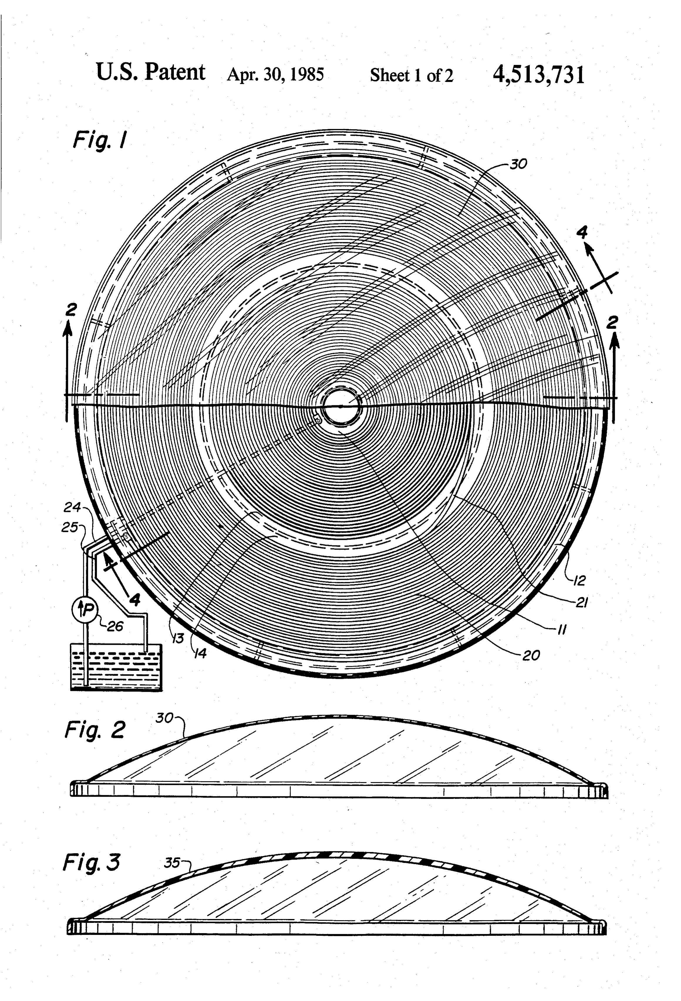
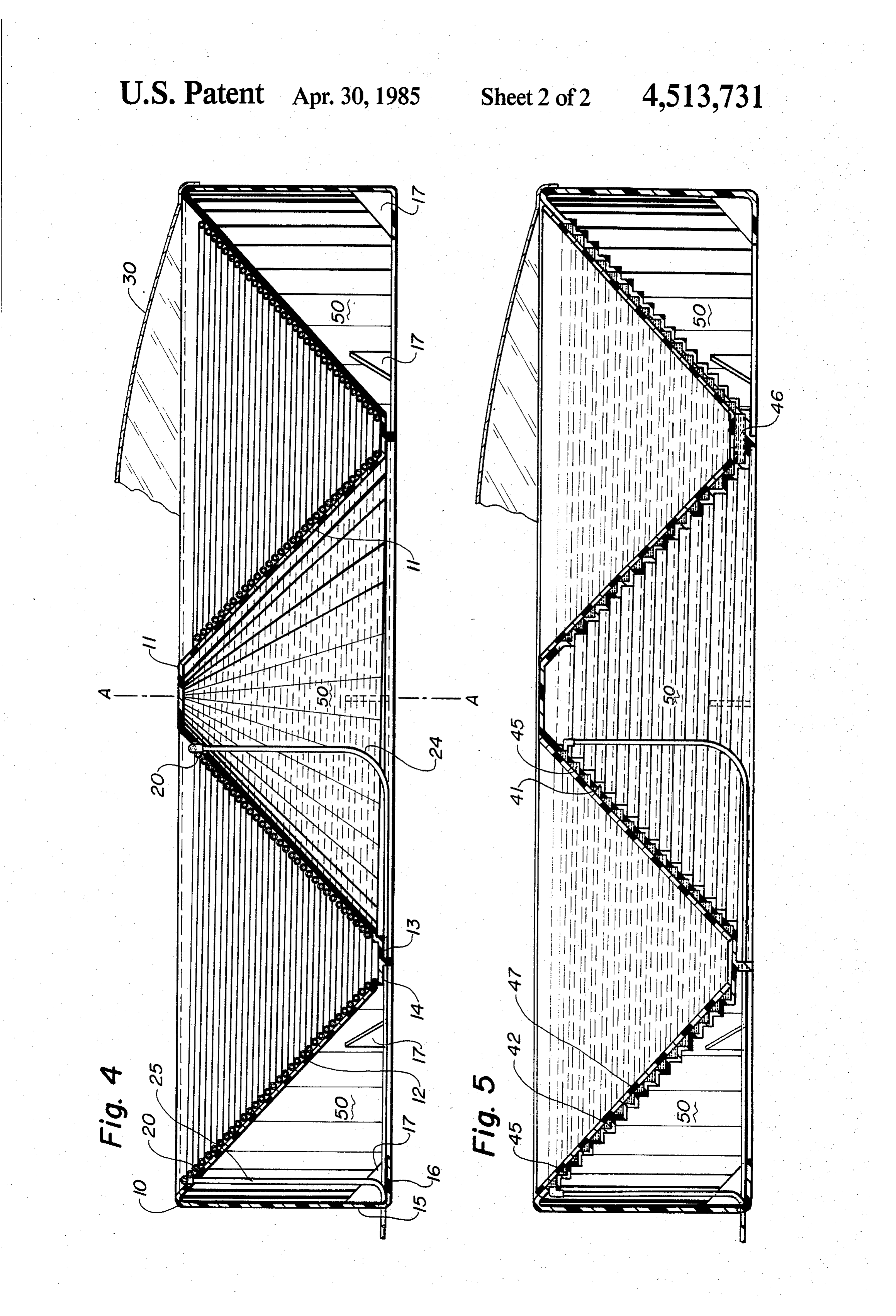
dicular to the sun's rays during the daylight hours. Fluid BRIEF DESCRIPTION OF THE DRAWINGS to be heated, e.g. water, enters the Thannhauser unit at the bottom of the cone-i.e. at its apex-and as it is In the accompanying drawings I have shown certain heated thermosyphon action causes it to move through present preferred embodiments of the invention in the tube in a spiral path toward the top of the unit where 45 which:
the outlet is located. FIG. 1 is a top plan view of a solar collector accord Thannhauser's thermosyphon is simple in design but ing to the invention, with half of its cover broken away; because it is a thermosyphon the rate of fluid circulation FIG. 2 is a sectional view of one embodiment of the through it is slow; moreover, if pump means were used cover taken along Line 2-2 of FIG. 1; to circulate the fluid at a higher rate, the single conical 50 FIG. 3 is a sectional view like FIG. 2 of another shape would have to be impractically high to provide embodiment of the cover which is thicker at the center sufficient heating surface for any significant heating. than at its edges and thus acts as a magnifier; Another disadvantage of the Thannhauser unit is that its FIG. 4 is a transverse sectional view of the collector upwardly open conical shape not only results in little if of FIG. 1, taken generally along the line 4-4 of FIG.1; any heating on overcast days but also acts as a cup to 55 and catch falling leaves, etc., thereby causing upkeep and FIG. 5 is a view like FIG. 4 of another embodiment cleaning problems. of the collector wherein fluid passages are formed inte SUMMARY OF THE INVENTION grally into the surface of revolution. I have discovered that many of the disadvantages of 60 DESCRIPTION OF THE PREFERRED both the Thannhauser thermosyphon and prior art EMBODIMENTS panel solar collectors can be eliminated by the solar Turning first to FIGS. 1 and 4, in which like numerals collector of my design. identify like features, there is shown a frame 10, which In accordance with the invention, I provide a solar may be fabricated from metals or non-metals-for ex heat collector for use at a predetermined latitude, com- 65 ample, polycarbonate or polyethylene could be used prising: (a) means forming a surface of revolution about satisfactorily. The frame serves as means forming a a generally vertical axis, said surface of revolution in surface of revolution about a generally vertical axis cluding (i) an inner, upwardly convex right conical A-A, which surface includes an inner, upwardly con 5 vex right conical frustum 11 and an outer upwardly ing through it, such that the rays are "trapped' within concave right conical frustum 12, the height of which is the collector and thereby provide additional heating of equal to that of the inner frustum. Base 13 of inner the fluid conduit means; this is the familiar "hothouse' frustum 11 is contiguous to the lower interior rim 14 of or “greenhouse' effect, and besides increasing heat outer frustum 12. Frame 10 may advantageously be input on clear days it enables the unit to absorb solar formed in one piece including an outer wall 15 and a heat even on cloudy days when fewer visible solar rays turned under rim 16 reinforced by gussets 17. strike the collecting surface.
I have found that for best operation the walls of frus The efficiency of my collector can be further in tums 11 and 12 should each have a rise angle (defined as creased by providing a cover 35 as shown in FIG. 3, in the acute angle formed by the wall of the frustum and a 10 which the thickness is greater at the center than at the plane perpendicular to axis A-A) equal to the latitude edges such that the cover acts as a magnifying glass to at which the collector is to be used plus from Zero to concentrate the solar rays within the collector. Selec about fifteen degrees. For example, in south central tion of the dimensions of such a magnifying cover is Pennsylvania, which is at about forty-one degrees lati within the skill of the lens-making art and the amount of tude, I may typically use a rise angle of about forty-five 15 magnification can be varied as desired by the user. Fab degrees. With such rise angle my collector does not rication of the cover, whether magnifying or not magni need to be tilted to face the sun, although tilting may fying, can be by any of several known manufacturing add somewhat to the collector's efficiency. techniques.
Tubing 20, which may advantageously be copper A possible disadvantage of the embodiment shown in tubing with its exterior surface treated to provide good FIGS. 1 and 4 is that the preferred copper tubing is light absorbing characteristics, serves as fluid conduit expensive and somewhat cumbersome to install on the means which define aspiral path along the outer surface surface of the frustums 11 and 12. FIG. 5 shows an of inner frustum 11 from the top to the base thereof, alternative embodiment which does not use separate cross from the inner to the outer frustum at the common tubing as conduit means. In the embodiment of FIG. 5, base, as shown at 21, and define another spiral path from 25 which is in other respects like that of FIG. 4, the fluid the lower interior rim to the upper exterior rim of the conduit means comprise channels 45 molded or other outer frustum 12. wise shaped into the surfaces of the inner and outer It will be appreciated that as shown in the drawing frustums 41 and 42. To retain the fluid, shown as 46 in figures the tube 20 forms a spiral coil having an inner FIG. 5, in the channels, a member 47 shaped conform section supported by the inner frustum, an outer section 30 ably to the frustums overlies the channels in sealing supported by the outer frustum and an intermediate relationship thereto. Member 47 may comprise either section connecting the inner section with the outer translucent material or opaque material, such as sheet section. Preferably, as also shown in the drawing fig copper, having a light absorbing surface. In either case, ures, the tubing of the inner and outer sections is wound the fluid path through the collector of FIG, 5 is substan tightly in stacked loops such that each individual loop 35 tially equivalent to that through the collector of FIG. 4. contacts an adjacent loop. Pipe 24 is connected to the Solar heat collectors according to the invention have inner end of tube 20 and serves as an inlet for fluid to be a number of advantageous features over collectors of heated; pipe 25, connected to the outer end of tube 20, the prior art. First, if the frame is fabricated from poly serves as an outlet for heated fluid. Because of the shape carbonate or other plastic type materials, colors can be of my collector, it will not function as a thermosyphon; molded into the frame providing a pleasing and unob consequently, the system must include means 26 for trusive finish for the units as installed. Second, the de circulating fluid to be heated through the pipe or other sign of the unit provides effectively the same collecting fluid conduit. Such circulating means may operate on area and/or volume as four to six standard flat panels of either the inlet or the outlet side of the collector, and the prior art. Third, given the fact that a typical unit for may be of any suitable type, such as pump or the like. It 45 domestic hot water use is approximately two feet high should be understood that the liquid travel path and by six to eight feet in diameter, the collector can be direction may be different from that discussed placed in a sunny area of a yard or the like with flowers hereinabove-e.g., pipe 25 could be an inlet and pipe 24 or shrubbery planted around it; thus the unit need not be an outlet. mounted on a roof as is often the case with flat panel As above indicated, the preferred embodiment of my 50 collectors, and accessibility is improved. Fourth, the collector includes a translucent, upwardly convex open area 50 shown in both FIGS. 4 and 5 under the dome-shaped circular cover 30, shown broken away in collecting surface, can be filled with insulating material FIGS. 1 and 4 and shown in cross-section in FIG. 2. and thereby provide a well insulated and more efficient The periphery of cover 30 engages the upper rim of heat collecting unit with very low losses from the unit outer frustum 12; efficiency can be increased if such 55 itself.
engagement forms a seal, but a seal is not required in the While I have shown and described certain present practice of the invention. For theoretically ideal opera preferred embodiments of the invention, it is to be dis tion the interior space should be completely sealed and tinctly understood that the invention is not limited under a slight vacuum. Cover 30, which may be fabri thereto but may be otherwise variously embodied cated from either glass or plastic, as long as the material 60 within the scope of the following claims. used is translucent, provides several advantages: First, it I claim:
serves to prevent leaves, snow, and other residue from 1. A solar collector comprising: falling into the collector and thus eliminates the chore a frame defining an opening having a first diameter; of periodically cleaning out the unit. Second, the dome a downwardly converging frusto-conical wall por shape helps to keep the surface of the cover itself clean 65 tion of smaller diameter than said first diameter and free from leaves and other debris which might positioned within said frame and attached thereto; collect on a flat or concave surface. Third, the cover an upwardly converging frusto-conical wall portion tends to alter the characteristics of ultraviolet rays pass of smaller diameter than the minimum diameter of 6 the downwardly converging frusto-conical wall portion positioned within said frame and within the portion positioned within said frame and within the downwardly converging frusto-conical wall por downwardly converging frusto-conical wall por tion and attached thereto, said upwardly and tion and attached thereto; downwardly converging wall portions having sub fluid conduit means lying in parallel displacement on stantially the same heights relative to said frame; the downwardly and upwardly converging wall fluid conduit means lying in parallel displacement on portions, said fluid conduit means being provided the downwardly and upwardly converging wall with inlet and outlet means to permit the flow of portions, said fluid conduit means being provided fluid into and out of said fluid conduit means, said with inlet and outlet means to permit the flow of fluid conduit means circulating fluid along a first 10 fluid into and out of said fluid conduit means, circu spiral path disposed on said downwardly converg lating fluid along a first spiral path disposed on said ing wall portion and a second spiral path disposed downwardly converging wall portion and a second on said upwardly converging wall portion, said spiral path disposed on said upwardly converging fluid conduit means being provided with a light wall portion, said fluid conduit means being pro absorbing surface to permit fluid to be heated by 15 vided with a light absorbing surface to permit fluid sunlight striking said fluid conduit means, said first to be heated by sunlight striking said fluid conduit and second spiral paths being interconnected; means, said first and second spiral paths being inter circulating means for circulating fluid along a circula connected;
tion path through said fluid conduit means, said circulating means for circulating fluid along a circula circulation path including both said first and sec 20 tion path through said fluid conduit means, said ond spiral paths; and circulation path including both said first and sec cover means fixed to said frame for covering said ond spiral paths; and fluid conduit means yet permitting the passage of cover means fixed to said frame for covering said sunlight thereto. fluid conduit means yet permitting the passage of 2. The solar collector of claim 1 wherein said circu 25 sunlight thereto.
lating means includes a pump in flow communication 10. The solar collector of claim 9 wherein said fluid with said second spiral path by said inlet means to intro conduit means includes tubing formed in a spiraled duce fluid thereto, said first spiral path having said outer coil supported by said downwardly converging outlet means associated therewith and with the return wall portion and in a spiraled inner coil supported by side of said pump such that fluid is circulated from said 30 said upwardly converging wall portion, said first spiral pump to said second spiral path via said inlet means, path being through said outer coil and said second spiral then flows along said first spiral path and is returned to path being through said inner coil. said pump via said outlet means. 11. The solar collector of claim 10 wherein the tubing 3. The solar collector of claim 2 wherein said fluid on both said inner and outer coils is wound tightly in conduit means includes tubing formed in a spiraled 35 generally vertically stacked loops such that the individ outer coil supported by said downwardly converging ual loops of tubing within each respective coil contacts wall portion and in a spiraled inner coil supported by each adjacent loop of tubing.
said upwardly converging wall portion, said first spiral 12. The solar collector of claim 11 wherein said frame path being through said outer coil and said second spiral is generally circular in shape.
path being through said inner coil. 40 13. The solar collector of claim 12 wherein said circu 4. The solar collector of claim 3 wherein said inlet lating means includes a pump in flow communication means inputs fluid at the top of said inner coil and said with said second spiral path by said inlet means to intro outlet means withdraws heated fluid from the top of duce fluid thereto, said first spiral path having said said outer coil, said inner and outer coils being intercon outlet means associated therewith and with the return nected at the bottom of said downwardly and upwardly 45 side of said pump such that fluid is circulated from said converging wall portions to permit the passage of fluid pump to said second spiral path via said inlet means, from said inner coil to said outer coil. then flows along said first spiral path and is returned to 5. The solar collector of claim 4 wherein the tubing said pump via said outlet means.
on both said inner and outer coils is wound tightly in 14. The solar collector of claim 13 wherein said inlet generally vertically stacked loops such that the individ 50 means inputs fluid at the top of said inner coil and said ual loops of tubing within each respective coil contacts outlet means withdraws heated fluid from the top of each adjacent loop of tubing. said outer coil, said inner and outer coils being intercon 6. The solar collector of claim 5 wherein said frame is nected at the bottom of said downwardly and upwardly generally circular in shape. converging wall portions to permit the passage of fluid 7. The solar collector of claim 6 wherein said cover 55 from said inner coil to said outer coil. means includes a dome-shaped cover. 15. The solar collector of claim 14 wherein said cover 8. The solar collector of claim 7 wherein said cover means includes a dome-shaped cover having a central has a central portion and a peripheral edge, said cover portion and a peripheral edge, said cover being thicker being thicker at said central portion than at said periph at said central portion than at said peripheral edge. eral edge. 60 16. A solar collector comprising: 9. A solar collector comprising: a frame defining an opening having a first diameter; a frame defining an opening having a first diameter; a downwardly converging frusto-conical wall por a downwardly converging frusto-conical wall por tion of smaller diameter than said first diameter tion of smaller diameter than said first diameter positioned within said frame and attached thereto; positioned within said frame and attached thereto; 65 an upwardly converging frusto-conical wall portion an upwardly converging frusto-conical wall portion of smaller diameter than the minimum diameter of of smaller diameter than the minimum diameter of the downwardly converging frusto-conical wall the downwardly converging frusto-conical wall portion positioned within said downwardly con 7 verging wall portion and attached thereto, said a domed cover affixed to said frame for covering said upwardly and downwardly converging wall por fluid conduit means yet permitting the passage of tions having substantially the same height relative sunlight thereto.
to said frame; 17. The solar collector of claim 16 wherein said frame fluid conduit means having outer and inner coils de 5 iswall cylindrical and includes a generally vertical exterior supporting said downwardly converging wall por fining first and second spiral paths, respectively, tion.
lying in parallel displacement on the downwardly 18. The solar collector of claim 17 wherein said and upwardly converging wall portions, respec downwardly and upwardly converging wall portions tively, said fluid conduit means being provided O are interconnected by a generally horizontally disposed with an inlet line for the introduction of fluid into said fluid conduit means and an outlet line for the lower planar transition member.
19. The solar collector of claim 18 wherein said inlet withdrawal of heated fluid from said fluid conduit means, said inner and outer coils being provided line inputs fluid at the top of said inner coil and said outlet line withdraws heated fluid from the top of said with a light absorbing surface to permit fluid to be 15 outer coil, said inner and outer coils being connected heated by sunlight striking said fluid conduit along said lower planar transition member. means, said inner and outer coils being intercon 20. The solar collector of claim 19 wherein said inner nected to permit the passage of fluid therebetween and outer coils are formed of tubing wound tightly in without exiting said solar collector; generally vertically stacked loops such that the individ a pump connected to said inlet and outlet lines for 20 ual loops of tubing within each respective coil contacts circulating fluid along a circulation path including each adjacent loop of tubing.
said first and second spiral paths; and : k
Provenance
- Collection
- Patents citing this work
- Pages
- 7
- Method
- pdftotext (the PDF's own text layer) + pdftoppm 300dpi page scans
- Patent office record
- patents.google.com →
- Source
- Google Patents citing-documents table
- Assignee
- Campbell Willis R
- Published
- 1985-04-30
- Transcribed from
- patentimages.storage.googleapis.com →