

patent · US2553292A
Dynamoelectric machine
15 May 1951
Text
Drawings
Page 1drawing sheetscan →
Page 2drawing sheetscan →
Page 3drawing sheetscan →
Page 4drawing sheetscan →
Page 5scan →
Patented May 15, 1951 2,553,292
United states patent office
Dynamoelectric machine
Edward L. Barrett, La Grange, Ill., assignor to
Edward L. Barrett and Ann K. Barrett, copart ners, doing business as Barrett-Keenan Com pany, Chicago, Ill.
Application November 20, 1948, Serial No. 61,173
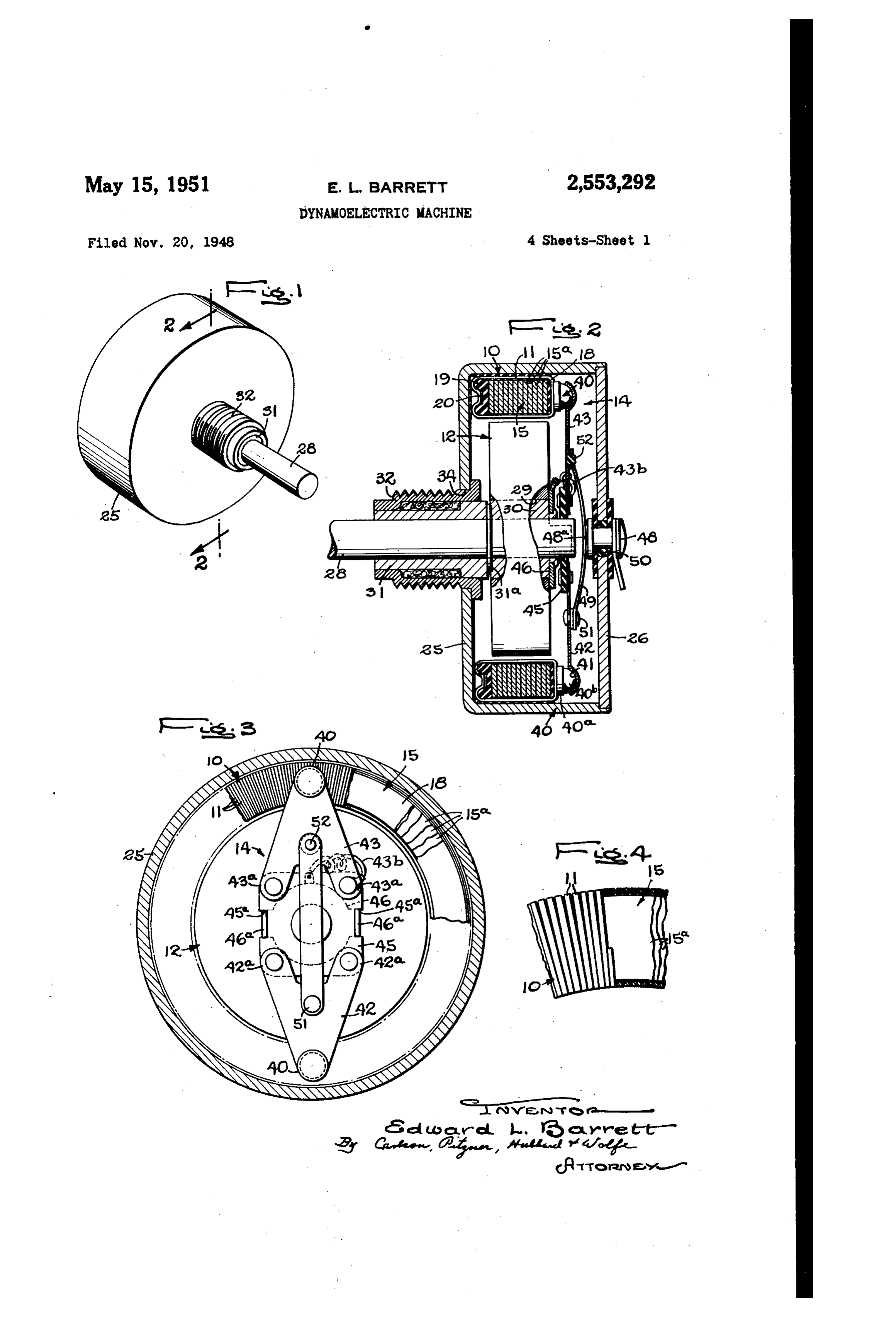
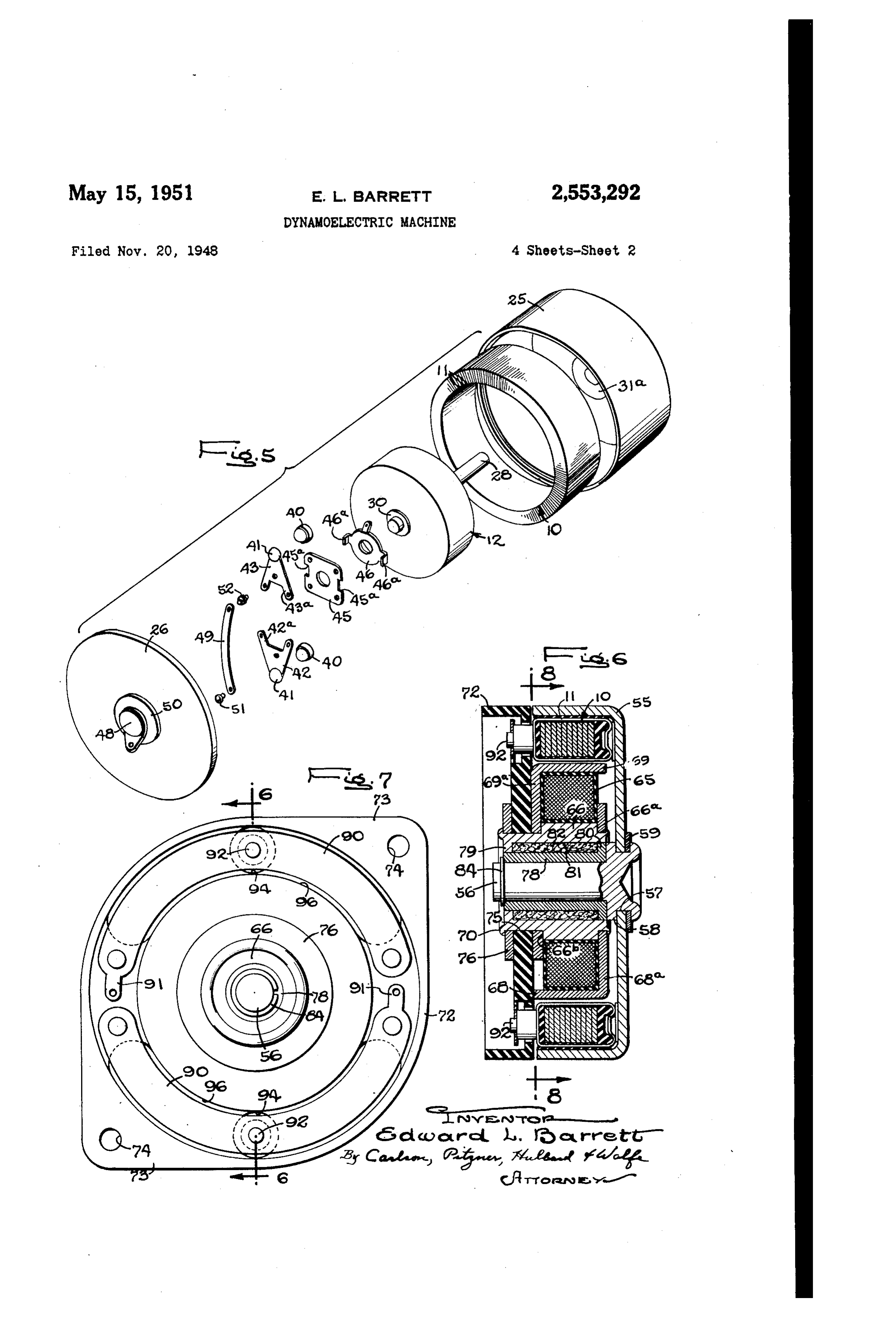
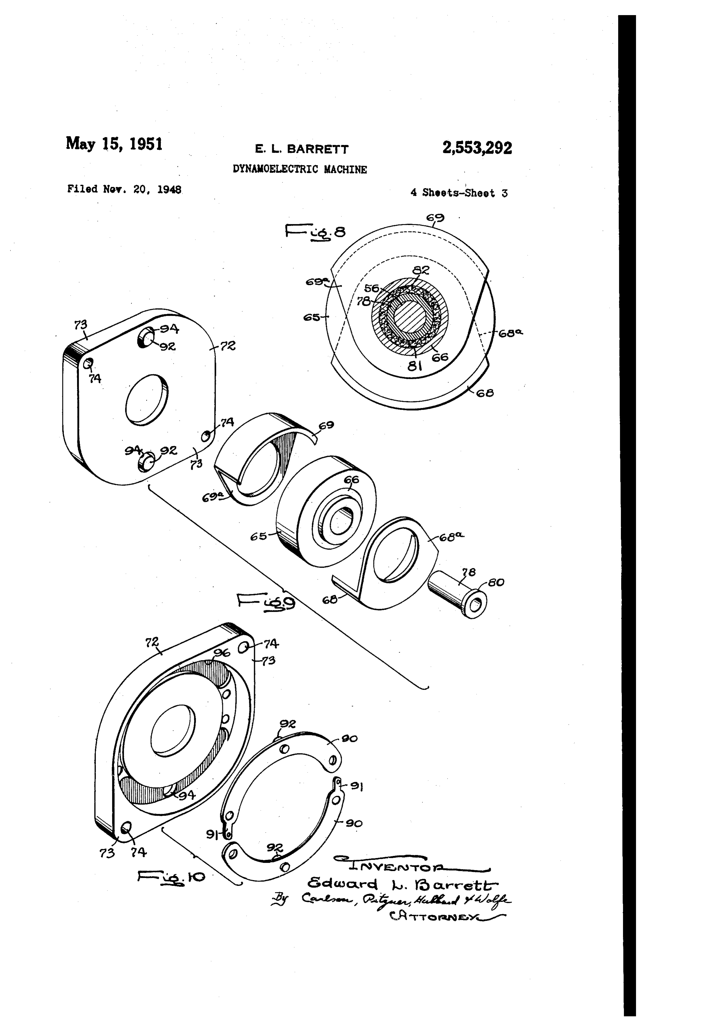
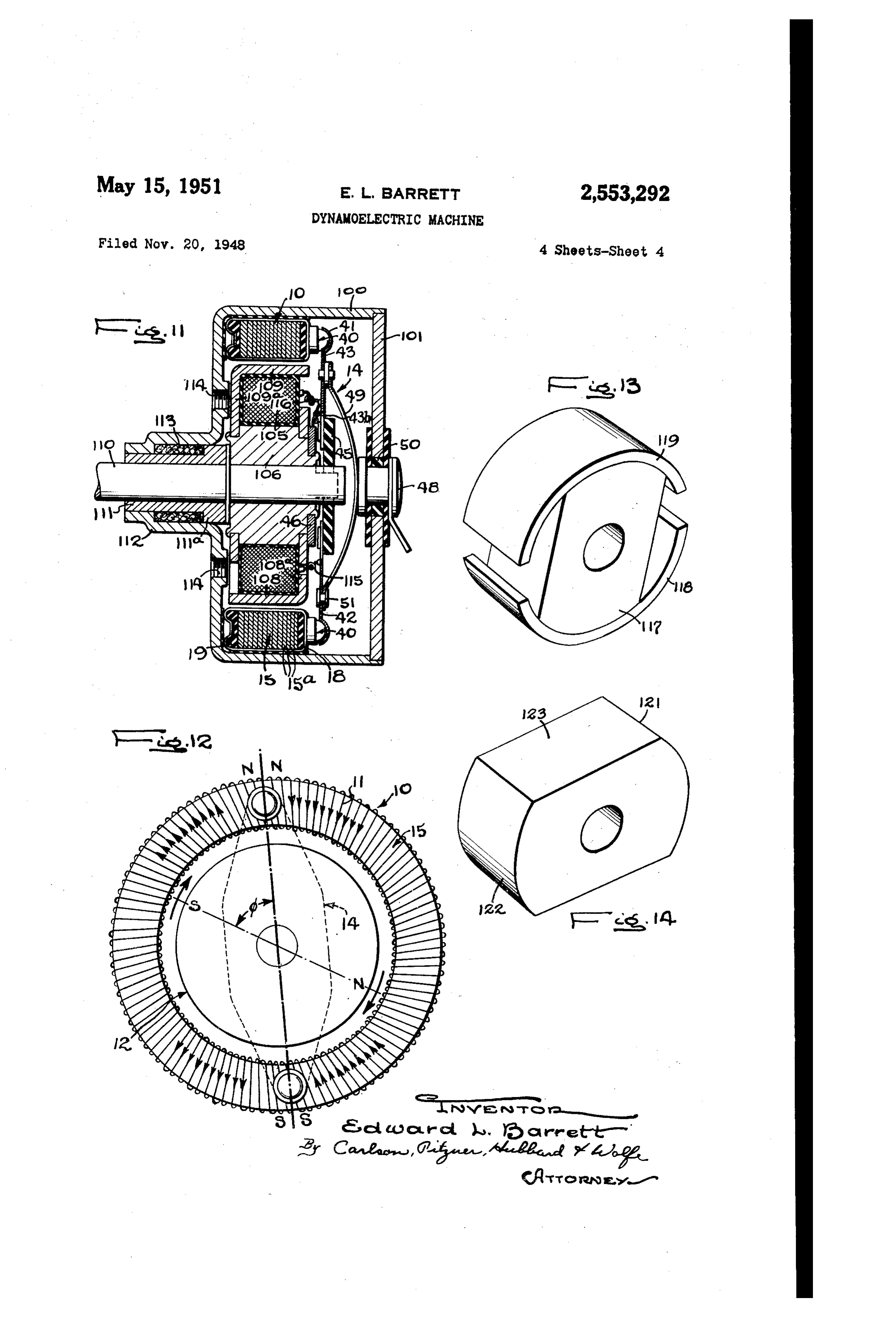
The present invention relates to dynamo elec Fig. 7 is an end view of the modified form of tric machines, and more particularly to improve notor illustrated in Fig. 6. ments in commutator type dynamo electric Fig. 8 is a transverse section taken Substan machines. tially in the plane of line e-8 in Fig. 6. One general object of the invention is to pro Fig. 9 is a fragmentary exploded perSpective Wide a dynamo electric machine intended primar view of the field elements and base portions of ily for use as a motor which is of exceedingly sim the modified form of the invention. ple construction and which permits of econom Fig 10 is a rear exploded perspective view of ical manufacture but is nevertheless efficient, the modifiedmotor base and brush structure. having a strong torque in relation to its size. O Fig.11 is a central longitudinal Section through A more specific object of the invention is to still another modified form of motor constructed provide a novel electric motor embodying an in accordance with the invention. armature of torodial form enclosing a field men Fig. 12 is a diagrammatic view showing: the ber and in intimate heat, conducting relation to basic elements of the invention as applied to a a cylindrical case for efficient cooling even under motor, indicating their relative positions and conditions of heavy overloading. those of their magnetic poles So that by magnetic A still further object lies in the provision of attraction rotation is produced. an electric motor of the above - character which Fig.13 is a perspective View of a modified form has itS brushes directly engaging the elements of of permanent magnet field member. the arnature Winding, doing away entirely with 20 Fig. 14 is a perspective view of another modi the usual commutator which not only enhances fied form of permanent magnet field member, compactness but Substantially eliminates com While the invention is susceptible of various mutation difficulties and insures constant torque modifications and alternative constructions, there for all rotor positions. It is a related object to are shown in the drawings and will herein be de provide a brush type motor having a minimum 25 scribed in detail several preferred embodiments, axial extent and in which the parts are snugly but it is to be understood, however, that there is telescoped together to produce maximum utiliza, no intention to limit the invention to the forms tion of Space. disclosed, but it is intended to cover all modifica It is another object of the invention to pro tions and alternative constructions falling within vide an electric motor particularly well suited for 3) the Spirit and scope of the invention aS eXpressed use in automobiles or the like which is durable in the appended claims.
both electrically and mechanically, requiring sub For purposes of exemplification and explana stantially no maintenance and well adapted for tion of its various novel features, the invention single hole mounting in the manner of a simple has been shown as embodied in several forms of rheostat. commutator type motors, the field being either a The objects of the invention thus generally set permanent magnet, or an electromagnet and the forth, together with other objects and ancillary armature in each case being of toroidal form. It advantages are attained by the construction and Will be appreciated that.the basic components, viz. arrangement shown by Way of illustration in the an armature and a field member together with a accompanying drawings, in which: brush assembly, permit of incorporation in an al Figure is a perspective view of an assembled most infinite number of forms and can thus be notor constructed in accordance with the pres readily adapted to the requirements of the par ent invention. ticular use desired. This motor is especially Fig. 2 is a central longitudinal section taken suited for operation from a low voltage, direct substantially in the plane of line 2-2 in Fig. 1 45 current Source of power Such as the conventional Fig. 3 is a plan view of the motor shown in the Storage battery in an automobile. The driving of preceding figures with the case cover removed, small control and indicator devices in aircraft, Fig. 4 shows a fragment of the motor armature windshield wipers and radio antenna. raising and in partial Section. lowering mechanisms in automobiles are but a Fig. 5 is an exploded perspective view of the 50 few examples of the fields in which the exem plary forms of motor find utility. Its compara motor ShoWn in the preceding figures. tively light weight and especially its extreme com Fig. 6 is a central longitudinal Section through pactness in proportion. to its developed torque, a modified form of the invention and taken. Sub render it especially Suited for use where space and stantially in the plane of line 6-6 in Fig. 7. Weight, are at a premium. Its high efficiency is 6 obviously desirable especially when it is to be sup the armature pressed into the housing 25 the plied from some limited power source such as an Outer Surfaces of the winding elements are in automobile storage battery. intimate thermal contact with the inner wall of In carrying out the invention (Figs, 1-5), an the housing but electrically insulated therefrom. arnature of annular form having an endless This contact between the winding and the casing toroidal winding if thereon is employed, together provides adequate cooling of the armature with With a field member 2 Which is preferably of out necessity for circulating air within the casing, generally cylindrical form and disposed within thus making it possible not only to totally enclose the arnature and a brush assembly 4 for Sup the motor but to reduce the included free space plying current to the armature. The brushes of 10 Within the housing.
the assembly 4 are in direct engagement with In the embodiment of Figs. 1-5 the field men elements of the winding at diametrically ber 2 comprises a Solid cylindrical disk or slug of Spaced points thereon and are rotatable relative magnetizable naterial having high magnetic re to the armature and fixed or stationary with re tentivity, alnico being a material Suitable for the Spect to the field member. s purpose. This cylindrical disk can be economical A particularly important feature of the inven ly formed by Simply Sintering a blank of the prop tion is the construction of the armature 9. In er size, which may be ground a Small amount for each of the embodiments shown it includes a core finishing, and then magnetizing it to manifest 5 made up of a series of flat ring laminations 5a, magnetic poles at diametrically disposed points on disposed in Stacked relation and which are of its periphery. Thereafter it is Supported on the ferromagnetic material of low retentivity such, motor shaft 28. For this purpose the slug has an for example, as silicon steel. On the ends of the axially disposed opening 29 therethrough. Within core f is are disposed insulating rings 8 and 8, which is received an annular bushing 33. The the outer surface of the ring 8 being flat and bushing 39 is force fitted on the end of the motor the outer surface of the insulating ring 9 being 25 shaft 28.
provided with a channel 29. The winding , it is to be noted particularly that since the rotor Which is of toroidal form is preferably formed 2 is of such limited thickness, the shaft, 28 can Of enameled Wire of Square croSS-Section and is be Supported in a single sleeve bearing 32, there disposed about the core, being electrically in by further enhancing the compactness and econo Sulated therefrom, with its free ends spliced to 30 iny of innanufacture of the notor. The Sleeve gether to make the Winding endless. Such con bearing 3 is, in turn, received in a housing 32. struction of the core permits comparatively loose The latt3r extends through a centraliy disposed Wrapping of the winding i? about the core, pref Opening 34 (Fig. 2) in the motor case 25, and is erably with the adjacent elements or turns there fixed therein by expanding its inner end into of lying against each other on the inside of the tightly fitting engagement With Wall of the open toroid, upon initial fabrication of the armature ing 29 or by brazing. A steel bearing washer 3 d. and the eafter the Winding is tightened by Stak is preferably provided at the inner end of the ing or crimping it into the channel 29. The ele Sleeve bearing 3.
ments of the winding are thus drawn flat, across The bearing housing 32 also provides a conven the outer surface of the ring 8. If desired the ient means for mounting the motor, and for this ringS 5a comprising the laminations of the core purpose it is externally threaded for engagement may be initially deformed or warped so that upon of a nut, permitting single hole mounting in the staking of the winding into the channel 20 and Inanner of a radio Volume control. thereby flattening out the rings a slight tension Turning now to the brush structure 4 it will ba Will be maintained on the winding When the noted that it includes brushes 40 having cylin armature is in finally assembled form. dirical portions 4ia, with flat bottom surfaces in After completion of the assembly of the arma engagement With the flat top surface of the arma ture Winding , and hemispherical portions Ago ture the enamel insulation on the outer surface of the flat portions of the winding elements adja received in correspondingly formed sockets gi cent the end ring 8 is removed thus baring the fashioned adjacent the ends of diametrically dis Successive convolutions to provide a plane flat posed arms A2 and 3. The arms 52 and G3 are annular commutating Surface disposed in a plane formed of resilient, electrically conducting ma Substantially perpendicular to the axis of the ima terial and are of generally triangular shape hav chine for direct engagement by the brushes of ing lugs A2a and 4.Sa, respectively, at their inner the brush assembly 4. It can be seen, there ends by means of which they are riveted or other Wise rigidly Secured to a central supporting plate fore, that this results in several advantages: first, 45 no additional commutator structure is required; of insulating material.
Second, commutation is Substantially perfect To obtain relative rotation between the brush since the turn to turn voltage is low and since, structure f4 and the armature 8, the former is drivingly coupled to the shaft 33. To this end as One Winding element is engaged by a brush, t50 there is provided a driving yoke 46 (Fig. 5) having a complementarily disposed winding element on Oppositely disposed, axially extending ears 4 Ga. the opposite Side of the toroid passes out of en gagement With the other brush; third, there is a thereon, Which is force fitted on the end of the considerable Space and weight saving; and fourth, Shaft 28. The ears 43a are received in notches the material and operations required in the manu 65 45a provided therefor in the insulating plate 43 facture of the device are minimized. to Which the brush ari as 42 and 43 are secured. The exemplary motor illustrated in Figs. 1 The driving yoke is so oriented that an angle b is through 5 inclusive, embodies a generally cylin maintained between the brush axis and the axis drical cup-shaped casing 25 having its open end of the magnetic poles of the field member 2. closed by an end cap 26. The casing 25 forms 70 This angle will be subsequently referred to. a protective enclosure, and is preferably made of The connection between the yoke 46 and the non-magnetic material having good heat con insulating plate 45 is such as to permit free axial ducting properties such as brass. This casing is movement of the plate, and thus of the Winole Snugly telescoped over the armature winding, the brush Structure, relative to the shaft and rotor latter being stationary in this instance. With 5 to the end that Some end play of the shaft and 7 the rotor is permitted without. altering the Con ing wall. After the housing... has been. So dis tact pressure between the brushes aind the arrina: posed on the end of the shaft, a. Washer. 59 is then ture. slipped over the shaft and thereafter the end Current is supplied to the brush an 32 by Way of the shaft is upset so that the wall of the of a contact, stud 48, and a contact Spring 49. The housing is clamped between the Washer and the stud 48 is supported centrally of the case, cover 26 peripheral flange 58.
in an insulator 50. As shown, the studis. of rivet In this embodiment it. Would be possible to like form presenting a fiat face 4.8d for engage use a slug of permanently magnetized alnico foi ment with the spring $9. The latter comprises a, the field member but I prefer to use an electro strip of flat, resilient, electrically conducting Xia O magnet having a coil. 65 wound on an annular terial, arching bridge-like between the brush airls soft iron core 66. This has the additional ad 42 and 43 across the end of the shaft 23, and hav vantage, if desired, of providing means for drop ing one end secured to the arm 42 and electrical ping the applied voltage. Diametrically disposed ly connected thereto. as by a rivet 5:4. The other With respect to the coil. 65 and the core 65 are end of the Spring 49 is secured to the blush a?: arcuate pole pieces 68. and 69 also of magnetic 43, but is...insulated therefrom by the insulator 32. material, being supported in. Such position, by Since...it is.common in electrical circuit.S. to have integrally formed arms 8a, and 69a, respectively, one: Side thereof grounded, in the instant motor which are rigidly secured to the opposite eiads...of the brush arm, 43 is connected to the case 25, and the core 66. In the present instance, the cen thus to ground, by Way of a pigtail connection 2C) tral portion of the coreig. of larger diameter than 43b, the yoke. AS, the shaft, 28, bearing 3i and the its end portions: thus providing shoulders: 63d bearing housing 32. Since the brush structure is aid $5b against which the pole, piece arms are reversible by 180° on the yoke. 46, a reversal of the abuttingly received.
direction of rotation, can be obtained by Simply To mount the instant motor a mounting plate reversing the positions of the brush airins 42 and or base 2, which is preferably of insulating ma 43. This, is done simply by removing the notor terial, is provided. As shown, the base has op case.cover 26 and lifting the brush assembly is so positely disposed lugs 3 integrally formed there as to disengage the notches 45d and driving yoke with which, in turn, are provided with holes. A ears 43d, and then rotating the asserably thirough for the reception of mounting. bolts, or the like. 180°. Thus, this form of the invention is adapt 30 As previously set, forth, in this... eighbodiment able for use. With electricai Systems, such for ex the field member comprises the stator, and thus ample, as those in automobiles where either the it is fixed to the mounting, base 2 for this negative Side: Or the positive Side inay be ground purpose the annular core. 66 is extended. So, as ed, but in which a certain direction of rotation is to paSS througia, an aperture 5. located cantrally required. This novel mounting also permits 55 of the base 2. Since: the material of the base..is ready replacement of the brushes Without dis preferably of insulating material and thus...may turbing any of the other elements of the brush be either comparatively soft or brittle, a washer Structure. S is placed over the projecting core. end and Other advantages also result from the con. the latter is upset a.s. at so. as to grip, the struction of the brush assembly f4 as set forth i washer, base and pole piece arm 69.a. in sand above. The engagement of the flat central por Wiched relation against the core: shoulder, 3. tion of the contactor 49. With the flat face 480, The annular core: 63-serves. additionally as a of the Stud 48 prevents any tendency for the housing and Support for a sleeve bearing 3, in assembly 4 to “roll' about an axis extending longitudinally of the assembly. Further, the bail 45 which end, the-motor shaft, 56 is..journaled. To... this the core is provided. With an in Wardly, ex and-socket joints between the brush arms 2 and tending flange 79 at its inner end, and the bear 43 and the brushes 49 permit. “floating,' or free ing is provided with an outwardly extending rocking movement, of the brushes so that their shoulder 8, at its outer end, the flage aing entire flat Surfaces are maintained in engage shoulder being of Such diameter as to. Singly ment with the armature winding , several ad 50 engage the bearing and core, respectively, and jacent turns of the winding being simultaneously thereby support the bearing. It will be inated engaged by each brush. At the Sarine tine low that the fange 29, the shoulder 36, the in Ener resistance: connections between the upper hemi Surface of the core 66, and the outer Strface'...of spherical brush portions 49b and the brush artin
SocketS 4 are maintained. An even contact 55 the bearing 78 define an enclosed, annular space 8 completely surrounding the bearing. which pressure obtains on both brushes through the may be utilized to contain oil soaked packing teeter-totter action of the assembly and the fact 82, from which the bearing 8, preferably of that an equal force is exerted at each end of the porous metal. Such as sintered bronze, is a de Spring. 49. quately lubricated.
In FigS. 6 through 10 inclusive, a modified 0. The shaft 53 is retained in position in the form of motor embodying the present invention bearing 3 by engagement of the shaft shoulder is illustrated.having certain novel features of con 58 with the outer bearing shoulder 8) and by struction not possessed by that already described. means of a snap ring 34 received in a periph In this form, the armature C, which is in all eral groove provided on the projecting end of respects the same as that hereinbefore set forth, 35 the shaft.
comprises the rotor for the motor, and the field Since, the field member in the instant embodi. member comprises its stator. Thus, the airna ment comprises the stator for the metGr, the ture 0 is received in a generally cup-shaped brush assembly as well as the field member, is housing 55 which is fixed to a rotatably journaled conveniently mounted on the base 2. As illus shaft 56. To fix the housing 55 on the shaft 55, 70 trated in Figs. 6 and 7 and to enable linites as shown, the housing is provided with a central rocking of the brushes to maintain all over brush opening 5 in its outer wall for the reception of contact, the brush assembly includes: a pair, of the end of the shaft 56. Adjacent its end the arcuate arms 9 of resilient, electrically coindusct shaft 58 is provided with a peripheral flange 58 ing material fixed at their outer ends; to the for engagement with the inner side of the hous- 75 underside of the base and in iuxtaposition with 8 the airmature 0, and having lugs 9 thereon to essary, the elements of the assembly being denoted permit connection with a Source of power. Cen by the same reference numerals. trally thereof, the arms 9) are apertured to re To supply current to the coil 05 of the field ceive the outer ends of the brushes 92 which, aire member pigtail connections 5 and 6 are made of generally cylindrical form. The brushes ex between the brush arms 42 and 43, respectively, tend through diametrically disposed openings Si and the coil. These enable the brush assembly to provided therefor in the base 2 So that tiheir be free floating.
fiat inner faces engage the flat end of the In Figs. 13 and 14 there are illustrated tWO toroidal winding of the armature. To perinit additional forms of field members Which may be free flexing of the brush arms 90, the undersideO used either as rotors or as stators. The form of the base 72 has arcuate channels 93 provided illustrated in Fig. 13 comprises a central, perma therein which are located beneath the arrins and nently magnetized, solid slug of material of are of a width enabling adequate clearance. high magnetic retentivity having arcuate outer It will be apparent that this form of the inven faces to which are rigidly secured pole pieces 8 tion readily permits of incorporation in fans or and 9 of generally semi-cylindrical form, their blowers simply through the provision of generally adjacent ends being spaced apart. In the form radially extending blades on the case 55. Such illustrated in Fig. 14 the field member comprises blades, would additionally facilitate Cooling of simply a slug 20 of magnetic material of high the motor itself. Further, the case can be fash retentivity, Such for example as alnico, having ioned to serve as the driving element of a gear 20 arcuate pole faces 2 and 22 and flatened sides train, as it can be provided with a ring or disk of 23. Both of these forms are somewhat more soft material such as rubber to permit its use in simple than the field member ShOWn in the illus friction type drive mechanisms. trative embodiment of Figs. 1-5 inclusive, pri While the foregoing discussion of this form of marily because it has been found somewhat easier the instant invention has been directed primarily to magnetize them. So as to present properly dis to its operation from a direct current Source of posed magnetic poles. In the form illustrated in supply it will be readily apparent to one skilled Fig. 13 the arcuate pole pieces may be of ordinary in the art that this form can be readily operated mid steel.
from an alternating current Source of Supply. The cperation of the illustrative embodiments Thus this form may be considered "universal.' 30 Of the instant invention will be apparent from In Fig. 11 there is shown still another modified the foragoing. However, by way of Summary, it form of motor embodying the instant invention. may be described briefly as follows. Consider In this embodiment the armature it is Stationary ing first, the armature , and referring particu and a rotating electromagnet used as a rotor. ially to Fig. 12 of the drawings, current Supplied The armature O is here received in a generally thereto from one brush flows in the Winding cup-shaped case 100 having its open end closed in two paths around the toroid, as is indicated by an end cap 01. As was the case for the form by the arrows, and leaves by way of the other of motor illustrated in Figs. 1 through 5, inclusive, brush. This current flow produces a magnetiza the case OO forms a protective enclosure for the tion of the core such that the core can be con motor and is preferably made of non-magnetic : sidered to be two arcuate bar magnets With like material such as brass. In this instance, the field oies together, these poles being manifested be member comprises an electromagnet Similar to neath the brushes as denoted N-N and S-S. that described for the form of motor illustrated Thus, as the brushes are moved relative to the in Figs. 6 through 10, inclusive, and thus it in anature the positions of these poles are COrre cludes a coil 05 wound on an annular core 66 spondingly shifted. The field member on the together with diametrically disposed arcuate pole other hand, whether it be of permanent magnet pieces 08 and 09 which are also of magnetic or electromagnet form manifestS magnetic poles material and which are Supported in diametri in fixed position. In the drawing these poles are cally disposed relation with respect to the coil and indicated by S and N. By fixing the positions core by integrally formed arms 0.8d, and 9a. 50 Of the brushes with respect to the field member The latter are rigidly secured to the opposite ends So that an off-set angle (b is maintained between of the core 06 in the same manner as described the polar axes of the field member and of the for the illustrative motor of Figs. 6 through 10. armature , Imagnetic attraction between unlike Received in the annular core is the shaft for magnetic poles produces movement of that mem the motor. The shaft to extends outwardly from her which is mounted for rotation. Such move the core 6 where it is Supported in a Sleeve ment shifts the brush positions relative to the bearing . The latter, in turn, is Supported in armattle and thus continuous rotation is pro a hollow housing 2 which, as Shown, is inte duced.
grally formed with the motor case 00. The outer While the foregoing sets forth the preferred end of the bearing housing 2 is of reduced dian O forms of the invention it will be readily appar eter and the bearing has an outwardly ex ent to one skilled in the art that many other tending shoulder if a. adjacent its inner end SO specific embodiments enhancing the instant in that the bearing is tightly fitted in the housing. vention can be produced including the use of a Between the bearing housing and the bearing field member of generally annular form disposed there is an enclosed annuiar chamber 3 Within 65 about the toroidal arnature, field members which may be disposed lubricant Soaked packing. manifesting more than a Single pair of magnetic Adjacent the housing extension the case it is poies in the Surface thereof adjacent the arma provided with a pair of screw threaded mounting ture and brush structures utilizing more than holes 4 for the reception of bolts or Similai one pair of brushes. Further, if desired, the mounting elements (not shown) for purposes of O arrnature Winding may be bared of insulation Support. for engagement by brushes on Surfaces other As illustrated in this embodiment, the brush than its end Surface.
assembly is identical with that shown for the I claim as my invention:
illustrative embodiment of Figs. 1-5 inclusive 1. In a dynamo electric machine having a field and thus a detailed description thereof is unnec s inenbei and a brush aSSembly, an armature 9 comprising a core embodying a series of flat ring fixed at their inner ends to said piate, brushes in laminations of ferromagnetic material of low terposed between the Outer ends of Said arms and magnetic retentivity and a pair of end rings of Said armature and direct engagement therewith, insulating material, one of said end rings pre a stud of electrically conducting material for con Senting a Sinooth Outer Surface and the other s nection with a Source of current being fixed in having a channel in its Outer Surface, an endleSS Said case and having a flat portion disposed in winding disposed about said core and deformed opposed relation to One end of said shaft, a coin into Said channel thereby tightening the Sane tact spring of flat resilient material bridging said about the core with the portions thereof for pre plate and shaft end and having its ends Secured sentation to the brushes of Said assembly drawn O to Said arms being electrically connected to one Snugly acroSS Said Smooth ring Surface, Said por of them and insulated from the other and cen tions being bared for direct engagement by Said trally thereof being in engagement with said fiat brushes. Stud portion, and means Operative to maintain 2. In a dynamo electric machine having a Said brush structure in fixed relation to said shaft field member and a brush assembly, an armature and to rotate the brush structure with respect to comprising a core embodying a series of flat ring Said arnature, the engagement of said flat con laminations of low magnetic retentivity each of tact Spring With said fiat Stud portion being said laminations having portions deformed out operative to prevent any tendency for the brush of the normal plane of the lamination, One end structure to roll about the axis perpendicular to of said core presenting a Smooth outer Surface 20 the rotational axis of said structure and to pro and the other end having a channel therein, an duce an even Contact preSSure On Said brushes. endless winding disposed about Said core and 6. In a dynamo electric machine having a field crimped into said channel to tighten the same member and a toroidal airnature one of which is about the core and dra W said aminations closely shaft mounted for rotation, a brush structure together whereby a slight tension is maintained comprising, in combination, a pair of brushes each on said Winding. having a portion for direct engageinent with the 3. In a dynamo electric machine having a case, Winding of Said armature, a Supporting plate of a shaft, a toroidal armature and a field member, insulating material disposed centrally of the brush a brush structure comprising, in combination, a structure and coaxially of the motor Shaft, a pair Supporting plate, a pair of brush arms of elec of brush arms Secured to said Supporting plate trically conducting material diametrically dis and maintaining the brushes in diametrically dis posed with respect to said armature with their posed relation to said armature, a Contact Spring outer ends overlying the same and fixed at their having coninection. With a source of electric cur inner ends to said plate, brushes interposed be rent and with one of Said arms, and a yoke rigid tWeen the outer ends of said arms and Said 3 5 With Said shaft and coupled With Said plate to arrnature and in direct engagement thereWith, a maintain said brush Structure stationary with re conducting stud projecting through said case but spect to said field member and to. rotate the same electrically insulated therefrom, a contact, Spring With respect to Said armature, said coupling be having one of its ends. Secured to one of Said arms ing disengageable to parinit rotation of Said being electrically connected thereto and being in 4. brushes through 180° with respect to said field engagement with said stud, and a driving yoke member whereby reversal of direction of irota rigid with said shaft and engaging Said plate to tion of the machine is obtained. rotate the brush structure With respect to Said 7. A dynamo electric machine comprising, in arnature. combination, a toroidal armature having an end 4. In a dynamo electric machine having a leSS insulated Winding wound on the Surface case, a toroidal armature and a field member, thereof, and having on at least one end thereof a brush structure comprising, in combination, a Substantially flat annular end face disposed in a supporting plate of insulating material, a pair a plane Substantially perpendicular to the axis of of brush arms of electrically conducting material the armature, the turns of the Winding being giannetrically disposed with respect to said arma arranged in a Single layer With adjacent turns ture With their outer ends overlying the same closely Spaced to one another, a relatively rotat and fixed at their inner ends to said plate, able field member cooperating therewith, and a brushes interposed between the outer ends of brush assembly for establishing an electrical cir said arms and Said arnature and in direct en cuit to said Winding and rotatable relative there gagement, therewith, a stud of electrically con to, Said Winding being bared of insulation on said ducting material for connection. With a Source one flat end Surface of the armature to provide a of current being fixed in Said case but insulated flat, Smoothly continuous and unobSructed con therefoin, a contact member having one of its Inutating surface, the brushes of said assembly ends secured to one of Said airns and being elec being provided with flat contact engaging sur trically connected thereto and being in engage 60 faces directly contacting Said commutating sur ment, with said stud, a driving yoke fixed with face.
i"espect to Said field meinber and engaging Said 8. In a dynamo electric machine having a field plate to rotate the brush structure with respect member and a brush aSSembly, an armature com to Said arrnature, Said yoke being oriented to prising a toroidal core consisting of a series of maintain a fixed offset angle between the axes 65 flat ring laminations of magnetizable material of the brushes and of the magnetic poles of the having low magnetic retentivity placed together field inenber. in Stacked relation and a uniform insulated con 5. In a dynafino electric machine having a case, ductor Wound tightly about the surface of said a shaft, a toroidal armature and a field member Core With the ends thereof secured together to disposed Within the armature, a brush structure O form an endleSS Winding, the turns of the Wind Comprising, in combination, a Supporting plate ing being arranged in a single layer with adja of insulating material, a pair of brush artins of cent turns closely spaced to one another, said resilient, electrically conducting material dia Winding at one end of the armature having a sub netirically disposed with respect, to said armature stantially flat annular surface disposed in a plane With their outer ends overiying the same and py perpendicular to the axis of the armature, said 10 surface being bared of insulation to provide a, an insulated endless winding thereon, one end of smoothly continuous and unobstructed commu Said armature being provided With a plane, flat tating surface directly engaged by the brushes annular commutator defined by annularly aligned of said brush assembly for establishing a circuit sections of Said Winding from which the insula to Said Winding. tion has been removed, said commutator being 9. In a dynamo electric machine the combina disposed in a plane Substantially parallel to the tion comprising a field member, a toroidal arma axis of said armature.
ture member including a flat annular commutat 17. The armature unit described in claim 16 ing surface disposed in a plane perpendicular to wherein said core member is provided with an an the axis of the armature, means for mounting said O nular recess into which said winding is pressed members for relative rotation, a brush structure to tighten the Winding about said core. having a pair of diametrically arranged brushes, 18. The arnature unit described in claim 16 each of said brushes having a plane flat face for Wherein a casing member is provided for the air directly engaging the flat commutating surface nature, Said casing being made of good heat con of the armature and having opposite Said 5 ducting material, and being Substantially cup face a hemispherically formed portion, said shaped, said armature fitting snugly within the brush structure further including hemispherically Casing and in heat transfer relation thereto formed sockets for the reception of the corre Whereby heat developed in the armature may be spondingly shaped portions of Said brushes to dissipated rapidly through said casing. permit free pivoting movement of the brushes 19. A dynamo electric machine comprising, in With respect to the arnature so that the brushes combination, a toroidal armature having an end can adjust themselves to maintain flat all over leSS insulated winding thereon and having on at contact with the commutating surface, and means least one end thereof a substantially flat annular for fixing the brush structure at an ange with end face bared of insulation and disposed in a respect to the field member for the setting up of plane Substantially perpendicular to the axis of a rotating field having a predetermined direc the arnature, a relatively rotatable field member tion of rotation. Centrally arranged in Said armature and having 10. A dynamo electric machine comprising in diametrical poles thereon, and a brush assembly Combination a roor member and a stator men Coaxially With said field member, said brush as ber mounted for relative rotation, one of said Sembly being provided with a cross member fixed members including a toroidal form core and an at an angle With respect to the poles of said field endless insula, led Winding thereon, said one mem member and having a pair of diametrically ar ber being provided at one end thereof with a ranged brushes thereon, each of said brushes hav. plane, flat annular commutator defined by an ing a fiat con-act surface fiatly engaging the nularly aligned sections of said winding from end face of Said armature and each being mount Which the insulation has been removed, the other ed on Said CroSS member for limited rocking of Said members being provided with a pair of movement to insure Self-alinement of the brushes field poles, a pair of brushes, each of said in a position of flat, over-all contact. brushes being provided with a plane, flat commu 20. A dynamo electric machine comprising, in tator engaging face, and a mounting for the Combination, a toroidal armature having an end brushes for positioning them with the flat faces less insulated winding wound on the surface thereof in relative sliding contact with said com thereof in a single layer with adjacent turns mutator, said mounting including means for per closely Spaced to one another, and having on at mitting limited rocking movement of each of said least One end thereof a substantially fiat annular brushes to insure that the brushes assume posi end face bared of insulation and disposed in a tions of flat, all-over contact on said commu plane Substantially perpendicular to the axis of tator. the armature to form a flat and uninterrupted 11. A dynamo electric machine described in Connutating Surface, a stationary field member claim 10 Wherein Said plane, flat annular com centrally arranged in said armature and present mutator is disposed in a plane substantially per ing diametrical poles to the inner surface of said pendicular to the axis of rotation of said ma arnature, means for mounting said armature for Chine. rotation about said field member, and a station 12. A dynamo electric machine described in alry brush assembly coaxial with said field mem claim 10 wherein Said brush mounting means in ber and provided with diametrically arranged cludes a universal joint for movably supporting 5 5 brushes, each having a flat contact surface flatly each brush. Whereby to maintain the plane, flat engaging the end face of said armature and face thereof in substantially co-planar relation Covering a Substantial portion of the width there ship with the Surface of the commutator. of for establishing an electrical circuit to dia 13. A dynamo electric machine described in metrical points on Said armature which are ar claim i0 wherein said brush mounting means in ranged at an angle relative to the poles on the cludes a ball and socket joint for movably sup field member.
porting each brush whereby to maintain the 21. A dynamo electric machine comprising, in plane, flat face thereof in Substantially co-planar combination, a mounting plate, a toroidal arma relationship with the surface of the commutator. ture having an endless insulated Winding thereon 14. A dynamo electric machine described in and mounted for free rotation adjacent said claim 10 Wherein the plane, flat, face of each mounting plate, said armature having on the brush is Substantially circular in outline and inner end thereof facing said mounting plate a of an area to simultaneously contact several suc Substantially flat annular end face bare of in ceSSive Sections of said Winding. Sulation and disposed in a plane Substantially 15. A dynamo electric machine described in perpendicular to the axis of rotation of the air claim 10 wherein said toroidal core is provided nature, a field member mounted on said Inount With an annular recess into which said winding is ing plate and having diametrical poles thereon preSSed to tighten the winding about said core. Spaced closely adjacent the curved inner surface 16. In a dynamo electric machine, an arma of Said armature, a pair of stationary brushes on ture unit comprising a toroidal form core having 75 Said mounting plate each having a fiat contact 11 surface for engaging diametrical points on said structure having a pair of diametrically arranged armature, and means for resiliently mounting brushes, each of said brushes having a plane flat said brushes on said mounting plate while per face for directly engaging the flat commutating mitting a limited amount of rocking movement to surface of the armature, said brush structure maintain the contact surfaces of Said brushes in further including means for mounting the flat all over contact with the flat end face of said brushes for ball-and-socket movement with re armature. spect to the armature so that the brushes main 22. A dynamo electric machine comprising, in tain flat all over contact with the commutating combination, a mounting plate, a rotor member surface, the brush structure being fixed at an including a cup facing said mounting plate and () angle with respect to the field member for the having a central shaft and a bearing for rota Setting up of a rotating field having a prede tively mounting the same on said mounting plate, termined direction of rotation.
a toroidal armature having an endless insulated EDWARD E. BARRET. winding thereon and Snugly telescoped within the
Cup, Said armature having on the inner end s REFERENCES CTED thereof facing Said mounting plate a substan The following references are of record in the tially flat annular end face bare of insulation file of this patent:
and disposed in a plane substantially perpendicu lar to the axis of rotation of the armature, a field UNITED STATES PATENTS member mounted on said mounting plate and 2) Number Name Date having opposite poles thereon spaced closely 218,520 Gramme ----------- Aug. 2, 1879 adjacent the curved inner surface of said arma 354,538 Curtis et al. --------- Dec. 21, 1886 ture, a pair of stationary brushes on said mount 406,015 Wilson ------------- June 25, 1889 ing plate each having a fiat contact surface for 423,912 Diehl ------------- Mar. 25, 1890 engaging diametrical points on the armature, 25 470,194 Hosford ------------ Mar. 8, 1892 and a resilient mounting for said brushes per 480,728 Kolben ------------ Aug. 16, 1892 nitting a limited amount of rocking movement 509,662 Hoffman ----------- Nov. 28, 1893 thereof to enable the brushes to accommodate 673,517 Eck ---------------- May 7, 1901 themselves to the armature in said rotor member 1,005,842 Hutches ------------ Oct. 17, 1911 for the maintenance of flat all over contact with 30 1,219,564 Kouyoumjian ------ Mar. 20, 1917 the flat end face of said armature. 1,811,180 Landers ---------- June 23, 1931 23. In a dynamo electric machine the combi 1,862,248 Wesnigk ------------ June 7, 1932 nation comprising a field member, a toroidal 2,194,211 Sansom ----------- Mar. 19, 1940 armature member including a flat annular com mutating surface disposed in a plane perpendicu- 35 OTHER REFERENCES lar to the axis of the armature, means for mount "Midget Motor,' pp. 66, 67 of "Power Genera ing said members for relative rotation, a brush tion,' March, 1948.
Provenance
- Collection
- Patents citing this work
- Pages
- 11
- Method
- pdftotext (the PDF's own text layer) + pdftoppm 300dpi page scans
- Patent office record
- patents.google.com →
- Source
- Google Patents citing-documents table
- Assignee
- Edward L Barrett
- Published
- 1951-05-15
- Transcribed from
- patentimages.storage.googleapis.com →