

patent · US4114057A
Dynamoelectric machine with inner and outer stators
12 September 1978
Text
Page 1bibliographic recordscan →
United States Patent (19) 11 4,114,057 Esters 45 Sep. 12, 1978 54 DYNAMOELECTRIC MACHINE WITH Primary Examiner-Donovan F. Duggan NNER AND OUTER STATORS Attorney, Agent, or Firm-Hauke and Patalidis 76 Inventor: Ernie B. Esters, 15915 Rutherford, 57 ABSTRACT Detroit, Mich. 48227
A dynamoelectric machine having coaxial inner and 21 Appl. No.: 748,091 outer stators and, preferably, also end stators, each 22 Filed: Dec. 6, 1976 stator being provided with a plurality of magnetic flux producing magnets, preferably of the permanent mag int. Cl’............................................. HO2K 37/00 net type. The rotor has a hollow cylindrical configura 52 U.S. C. ...................................... 310/46; 310/266; tion and is rotatably disposed such as to form a plurality
58 Field of Search ................... 310/43, 49, 152, 154, of magnetic gaps between the inner stator, outer stator 310/159, 266, 46 and end stators and a plurality of magnetic cores sup ported by the rotor and provided with appropriate 56 References Cited windings, the stator magnetic cores having projections
Stators, 3,396,296 8/1968 Esters ................................... 310/266 3,502,914 3/1970 Cox. .................................... 310/43X 3,602,749 8/1971 Esters ................................... 310/154 15 Claims, 4 Drawing Figures
onnart
Drawings
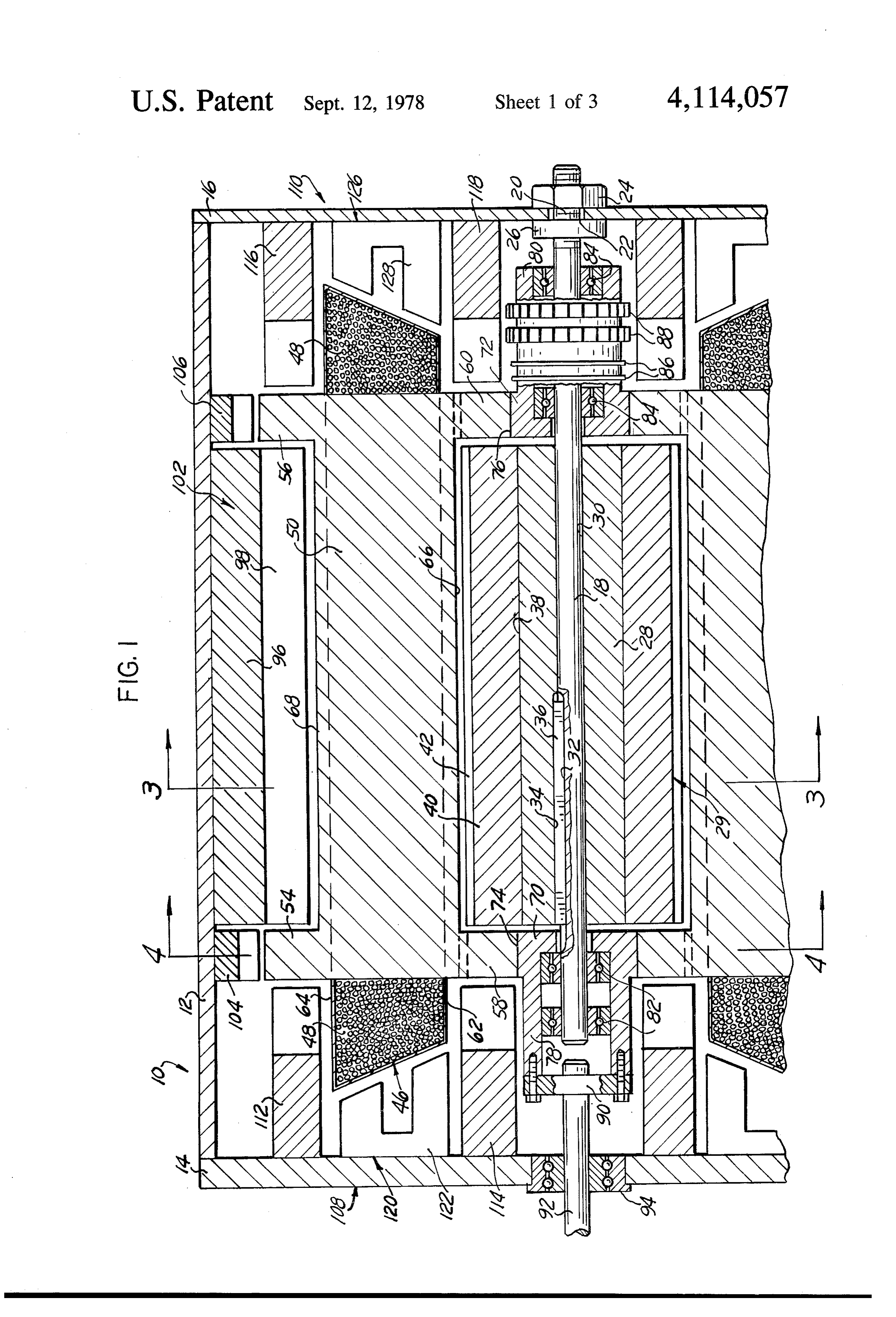
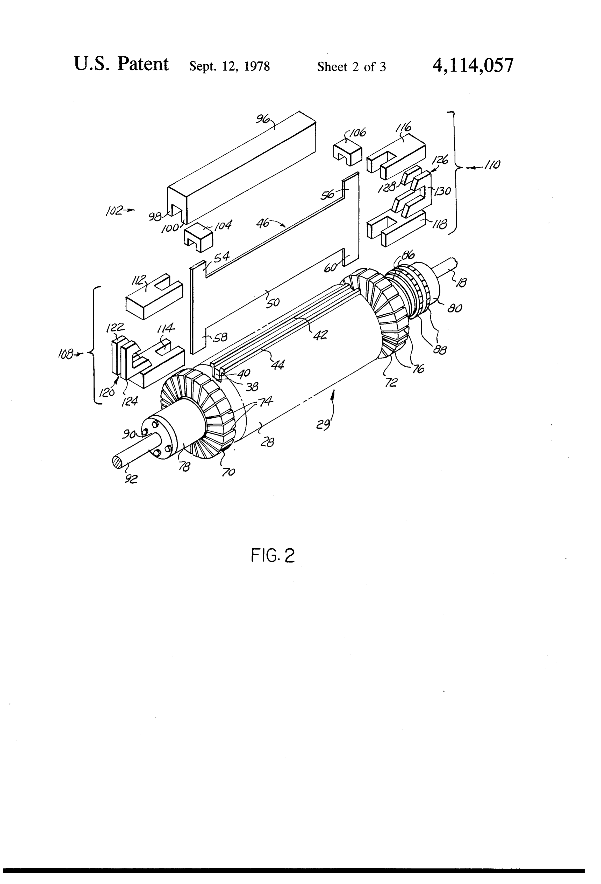
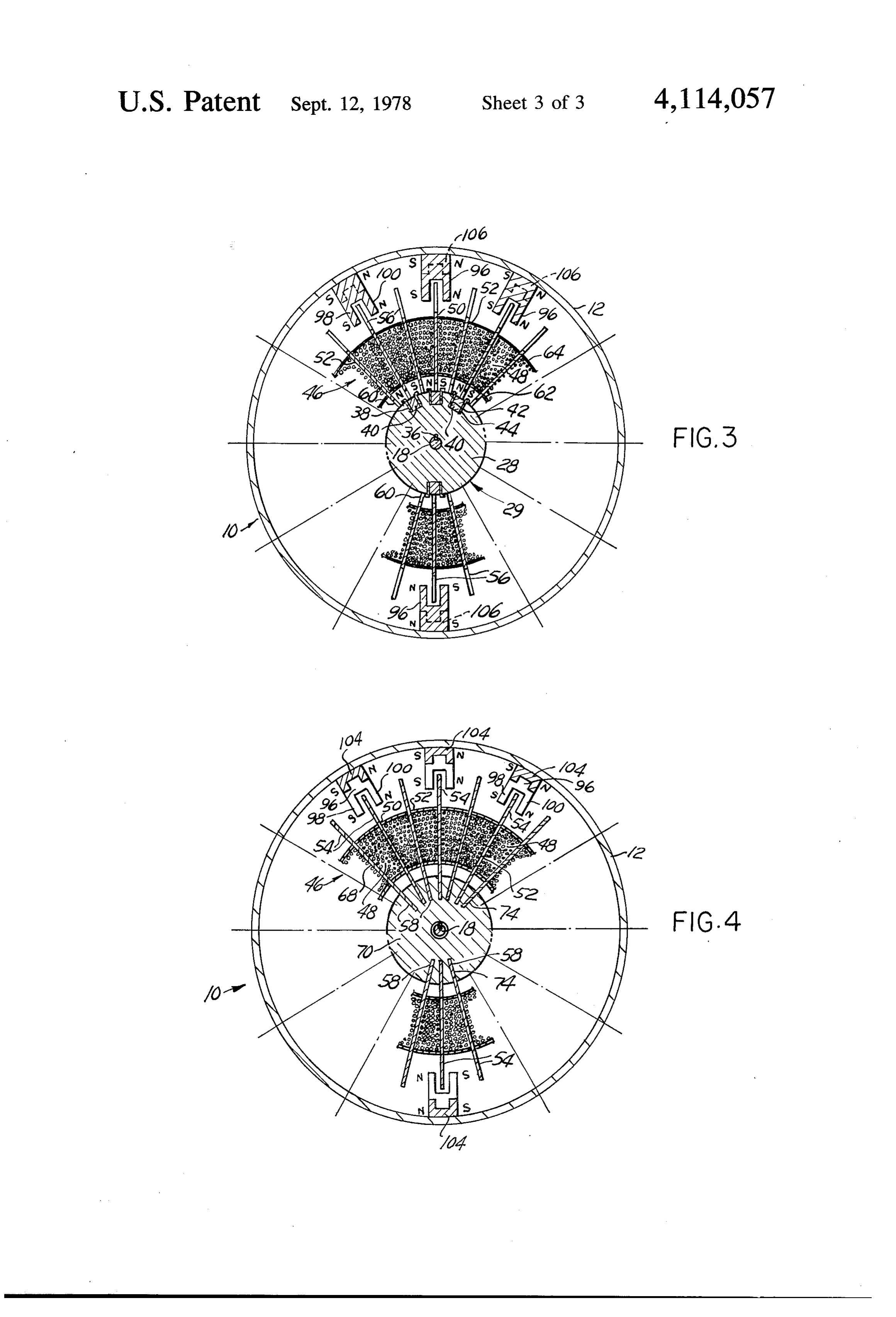
FIG. 2 is a schematic exploded perspective view of a shaped rotor keyed to a rotatable shaft. The stator or stators are axially arranged relative to the rotor such portion of a dynamoelectric machine according to the that the magnetic interface or gap, through which the present invention;
Page 2drawing sheetscan →
Page 3drawing sheetscan →
Page 4drawing sheetscan →
Page 5scan →
and radial gap type wherein attraction and repulsion
DYNAMOELECTRIC MACHINE WITH INNER forces, in a motor configuration, or induced EMF, in a AND OUTER STATORS generator configuration, are produced at a maximum CROSS-REFERENCE TO RELATED PATENTS 5 effective number of interfaces between the rotor mag netic cores and the stators magnets, preferably perma
The present application relates to an improvement on nent magnets, resulting in a very efficient dynamoelec Pat. No. 3,602,749, for "Dynamoelectric Machine', tric machine.
issued Aug. 31, 1971 and Pat. No. 3,729,642, for "Plural More particularly, the present invention contem Stator Dynamoelectric Machine", issued April 24, plates further improving the efficiency of the dynamo 1973. 10 electric machines disclosed in U.S. Pat. Nos. 3,602,749 BACKGROUND OF THE INVENTION and 3,729,642 by disposing the windings of the rotor around magnetic cores provided with end extensions,
The present invention relates to dynamoelectric ma such end extensions projecting radially outwardly and chines capable of operating either in a generator mode inwardly relative to the rotor windings, and disposing or in a motor mode and, more particularly, the present 15 additional magnets in the stators for interreacting with invention relates to dynamoelectric machines of the the magnetic core extensions, such as to further increase radial- and axial-gap-type. the efficiency of the dynamoelectric machine. In addi Dynamoelectric machines, motors and generators, tion, a further object of the present invention contem are generally of the radial magnetic gap type, being plates an improved support and journal construction for provided with an annular peripheral stator and a cylin 20 drical rotor disposed internally of the stator. Electrical the rotor magnetic cores and winding assemblies by providing massive end hubs for the magnetic cores, current supplied to the windings of the rotor or stator, or to the windings of both, generates electromagnetic with the inwardly radially projecting core projections fields in the rotor or in the stator, as the case may be. In support hubs.in appropriate radial slots formed in the electric motors, the electromagnetic fields react with 25 each other or with magnetic fields created by perma BRIEF DESCRIPTION OF THE DRAWINGS nent magnets to produce forces of attraction or repul The several objects and advantages of the present 'sion between the rotor and the stator which in turn cause the rotor to rotate in unison with a shaft support invention will become apparent to those skilled in the ing the rotor. In electrical generators, the rotation of the 30 art when the following description of the best mode rotor causes an electromotive force to be induced in the contemplated conjunction for practicing the invention is read in with the accompanying drawing wherein windings. In such dynamoelectric machines, the attrac like reference numerals tion and repulsion forces, and the induced electromo the several views and in refer to like parts throughout which:
tive forces, are created at the cylindrical magnetic inter face or gap between the rotor and the stator. 35 FIG. 1 is a partial longitudinal sectional view of a Another type of dynamoelectric machine, often re portion of a dynamoelectric machine according to the ferred to as the axial gap type, is provided with a disc present invention;
FIG. 2 is a schematic exploded perspective view of a shaped rotor keyed to a rotatable shaft. The stator or stators are axially arranged relative to the rotor such portion of a dynamoelectric machine according to the that the magnetic interface or gap, through which the present invention;
attraction or repulsion forces of the magnetic fields are FIG. 3 is a transverse sectional view thereof along exerted and the variable magnetic fields inducing an line 3-3 of FIG. 1; and electromotive force are created, respectively in motors FIG. 4 is a transverse sectional view thereof about and in generators, are axially or longitudinally aligned line 4-4 of FIG. 1 with respect to the housing and rotatable shaft of the 45 DETAILED DESCRIPTION OF THE dynamoelectric machine. PREFERRED EMBODIMENT * A third type of dynamoelectric machines, best repre sented by the structures disclosed in the above-men Referring now to the drawing, a dynamoelectric tioned U.S. Pat. Nos. 3,602,749 and 3,729,642 and also in machine 10 according to the present invention com *U.S. Pat. Nos. 3,426,224 and 3,396,296, all issued to 50 prises a generally cylindrical housing 12, FIG. 1, closed applicant, presents the combined advantage of both the at each end by end plates 14 and 16, the end plates 14 radial gap and axial gap dynamoelectric machines. In and 16 being fastened to the cylindrical housing 12 in such structures, a first stator is disposed within a hollow any convenient manner such as by means of screws, not 'cylindrical rotor and a second stator, also cylindrical in shown. A shaft 18 extends longitudinally through the shape, is disposed such as to surround the rotor. A dou 55 housing 12, concentric with the wall thereof, and is held ble radial gap dynamoelectric machine is thus formed. in a fixed position by being bolted, for example, to an In addition, end stators are provided on the lateral ends end plate, such as end plate 16. For that purpose, the 'of the rotor so as to form an axial gap between the ends shaft 18 has a threaded end 20 projecting through an of the rotor and the magnetic field created by the end aperture 22 formed in the end plate 16 and a nut 24, stators. An electric motor, or an electric generator, built when appropriately tightened on the threaded end 20 of according to such principle has a greater efficiency than the shaft 18, holds the shaft fixedly in position, as a conventional motors or generators, as a result of the result of the wall of the end plate 16 surrounding the greatly increased interreaction between a multitude of aperture 22 being clamped between the bottom of the magnetic fields and electromagnetic fields. nut 24 and a shoulder 26 integrally formed on the end of 65 the shaft 18. Additional securing means may be pro
SUMMARY OF THE INVENTION vided, not shown, such as pins, keyways and keys, and The present invention has for principal object the the like for preventing the shaft 18 from rotating rela provision of electric motors or generators of the axial tive to the end plates 14 and 16.
Page 6scan →
The shaft 18 supports a hollow cylinder 28 having a which are press-fitted or otherwise fastened the exten longitudinal bore 30 through which the shaft 18 is press sions 58 of the magnetic cores 50 and 52. The hub or fitted, for example, a longitudinal keyway 32 being disc 72 on the other end of the rotor 46 is similarly formed in the periphery of the shaft 18, and a corre provided with radial slots 76 in which are press-fitted or sponding keyway 34 being formed in the bore 30 in the otherwise fastened the inwardly projecting core exten cylinder 28, a key 36 being disposed in the mating key sions 60. The hub 70 is provided with a cup-like integral ways 32 and 34. The outer periphery of the cylinder 28 extension 78 on the interior of which are press-fitted, or has a plurality of radially disposed slots 38, FIGS. 1-3, otherwise fastened the outer races of a pair of ball bear each accepting a single elongated permanent magnet ings 82, the inner races of which are fitted over the end bar 40 and its pole pieces 42 and 44, made of magneti 10 of the shaft 18. In a similar manner, the hub or disc 72 is cally permeable material, the pole pieces 42 and 44 provided with an integral cup-like extension 80 sup being L-shaped in section, as shown at FIG. 3. In the ported from the shaft 18 by way of ball bearings 84. The structure illustrated, the cylinder 28, forming part of the cup-like hub extension 80 supports externally a pair of inner stator 29, is made of a non-magnetic material, rings 86, to which are connected the terminal of the preferably aluminum or an aluminum alloy, and is pro 15 windings 48, and a pair of commutator rings 88, in turn vided with twelve such slots 38 on its periphery, each appropriately connected to the rings 86. A pair of slot containing a permanent magnet bar 40 and its asso brushes, not shown, are used for bringing electrical ciated pole pieces 42 and 44 fastened in the slot by press current to the commutator 88 (motor mode) or for re fitting, for example. Each permanent magnet bar 40 is covering the electric current produced by the dynamo magnetically oriented transversely such that opposite electric machine (generator mode). On the end of the magnetic poles are disposed on opposite sides of the cup-like hub extension 78 is fastened, by means of a magnet bar 40 with the pole pieces 42 and 44 being coupling 90, an output (motor) or input (generator) alternate "north' and "south' poles for example. Con shaft 92 journalled through the end plate 14 by means of sequently, the magnetic poles about the periphery of the ball bearings 94 or the like. In structures wherein the cylinder 28, together defining the inner stator 29 of the 25 coupling 90 is a flexible coupling, some support and dynamoelectric machine 10 of the invention, are alter bearing means, not shown, is provided for peripherally nate N, S, N, S, etc., poles, providing a total of twelve N and rotatably supporting the cup-like hub extension 78. poles alternating with a total of 12 Spoles, regularly The magnetic pole pieces 42 and 44 of the magnets 40 disposed about the periphery of the inner stator 29, of the inner stator 29 are adapted to react with the The rotor 46 of the dynamoelectric machine 10 is 30 magnetic flux at the edge 66 of the rotor magnetic cores formed of a plurality of windings 48 each wound 50 and 52. U-shaped elongated permanent magnets 96 around a flat relatively thin magnetic core 50 made of a are mounted on the inner surface of the housing 12, and magnetically permeable material, such as steel, ferrite present alternate "south" and "north" poles on the ends and the like. In the example illustrated, there are twelve of their legs 98 and 100 for interreaction with the outer such windings 48 wound around every other magnetic 35 edge 68 of the rotor magnetic cores 50 and 52. The core 50, one further magnetic core 52 being disposed permanent magnets 96 may be cemented or otherwise between consecutive windings 48, as disclosed in detail fastened to the inner surface of the housing 12 and, in in U.S. Pat. No. 3,602,749. As explained in the aforesaid the example illustrated, define an outer stator 102 con patent, all the coils or windings 48 are electrically con sisting of twelve such permanent magnets 96 disposed at nected and are wound around their respective magnetic regular intervals and forming alternate S, N, S, N, S, N, cores 50, such that at any given time, the electric cur . . . poles.
rent circulating in the coils or windings 48 circulates in The outer stator 102 also comprises a plurality of the same direction, therefore creating in the magnetic small U-shaped permanent magnets 104 mounted proxi cores 50 a magnetic field radially directed. As the elec mate to one end of the long magnets 96 and adapted to tric current circulates in all the windings 48 in the same 45 interreact with the outwardly projecting magnetic core direction at a given time, magnetic fluxes in the same extensions 54, and a plurality of small U-shaped perma direction are provided by each core 50, while each core nent magnets 106, similarly disposed on the other end of 52 provides a magnetic flux in an opposite direction. each magnet 96, for interreaction with the magnetic Each magnetic core 50 and 52 has an extension radi core extensions 56. There are, in the example of struc ally disposed at each end of the core and extending 50 ture illustrated, twelve magnets 104 and twelve magnets outwardly. Such a core extension on one end of the 106, oriented magnetically in the same manner as the magnetic core 50 is designated by numeral 54 at FIG. 1, magnets 96.
and the other extension at the other end of the magnetic The present invention further contemplates provid core is designated by numeral 56. Similarly each mag ing end stators 108 and 110 disposed respectively on netic core 50 or 52 is provided with an inwardly pro 55 each end of the housing 12 and supported respectively jecting radial extension 58 on one end and an inwardly by the end plates 14 and 16. The end stator 108 comprise projecting radial extension 60 on the other end. The a plurality of horseshoe-shaped magnets 112, twelve in magnetic cores 50, with the windings 48 wound there number in the example illustrated, adapted to interreact around, and the alternate magnetic cores 52, between with the side edge of the core extensions 54 and a plural windings 48, thus define a hollow cylindrical rotor 46, ity of symmetrically disposed horseshoe-shaped mag provided with an inner cover 62 and an outer cover 64 nets 114 also twelve in number in the example illus made, for example, of varnished impregnated fabric or trated, adapted to interreact with the side edge of the paper and from which projects the inner edge 66 and magnetic core extensions 58. The other end stator 112, the outer edge 68, respectively, of the magnetic core 50 similarly, comprises a plurality of small horseshoe mag or 52, the rotor 46 being supported, on both ends 65 nets 116 for interreacting with the side edge of the mag thereof, by way of a hub or disc 70, on one end, and a netic core extensions 56 and small horseshoe magnets hub or disc 72 on the other end. Each support disc 70 is 118 adapted to interreact with the side edge of the mag provided with radially disposed slots 74, FIG. 4, in netic core extensions 60. The magnets 116 and 118 are 7 each twelve in number in the example of structure illus thin magnetic cores disposed each between consecutive trated. wound magnetic cores, the improvement comprising The magnets 112, 104, 96, 106 and 116 are trans each of said magnetic cores having at least at an end versely aligned in such manner as to all have an identi thereof a first extension integral with said rectangular cal pole presented to the core extensions 54, 68 and 56 5 plate projecting radially toward said outer stator and a at a given time during rotation of the rotor 29. The plurality of magnets in said outer stator disposed such as magnets 114, 40 and 118 are transversely aligned such as to form a radially magnetic gap with said first core to all present a magnetic pole of the same polarity to the extension.
core extensions 58, 66 and 60 at a given time during 2. The improvement of claim 1 further comprising a rotation of the rotor 29. Radially, however, the mag 10 plurality of magnets in at least one of said end stators netic poles presented by the magnets 114, 40 and 118 are disposed such as to form an axial magnetic gap with said opposite polarity to those presented by the magnets 112, first core extension.
104, 96, 106 and 116. 3. The improvement of claim 1 further comprising The end stator 108 in addition comprises a plurality of said first core extension at each end of said magnetic pairs 120 of horseshoe-shaped relatively thin magnets 15 cores and a plurality of magnets in each of said end 122 and 124, adapted to interreact with the correspond stators disposed such as to form an axial magnetic gap ing lateral end of the windings 48 and the corresponding with said first core extension.
lateral end of the magnetic cores 50 and 52. The other 4. The improvement of claim 1 further comprising a end stator 110 comprises a plurality of pairs 126 of rela second tively thin horseshoe-shaped magnets 128 and 130, 20 radially integral toward magnetic core extension projecting said inner stator at at least one end of adapted to interreact in a similar manner with the other said magnetic core and a plurality of magnets in at least lateral end of the magnetic cores 50 and 52 and wind one of said end stators disposed such as to form an axial ings 48. In the example of structure illustrated, there are magnetic gap with said second core extension. twelve pairs 120 and 126 of end magnets, and each magnet of a pair is reversed relative to the other such second integral magnetic core extensioncomprising 25 5. The improvement of claim 1 further projecting that N, S, N, S, . . . poles alternate at the ends of the inner leg of the magnets while S, N, S, N. . . poles radially magnetic toward said inner stator on each end of said core and a plurality of magnets in each of said alternate at the ends of the outer leg of the magnets.
It can thus be seen that the particular structure of the gap with saiddisposed end stators such as to form an axial magnetic winding magnetic cores of the rotor of the present in 30 6. The improvementcoresecond extension.
claim 4 further comprising a vention provided with end radial extensions results in hub member for rotatably supporting said rotor, said forming a plurality of interreacting magnetic gaps with the permanent magnets of the inner stator, the perma hub member having a radial slot corresponding to each nent magnets of the outer stator and the permanent core of said second core extension for fitting of said second magnets of the end stators, with the advantage that the 35 7. The extension in said slot. efficiency of dynamoelectric machines constructed ac improvement of claim 6 further comprising a cording to the invention is greatly increased as com ber. rotatable shaft having an end affixed to said hub mem pared to conventional dynamoelectric machines pro viding only a limited number of magnetic gaps between 8. The improvement of claim 5 further comprising a rotors and stators. It will be appreciated by those skilled pair of hub members for rotatably supporting said rotor, in the art that although the magnets of the stators are each of said hub members having a radial slot corre preferably permanent magnets of high reluctance, elec sponding to each of said second core extensions for tromagnets may be substituted for some or all of such fitting of each of said second core extensions in said slot. permanent magnets without departing from the spirit or 9. The improvement of claim 8 further comprising a scope of the present invention. 45 rotatable shaft having an end affixed to one of said hub Having thus described the present invention by way members.
of a typical example of structure according to the prin 10. The improvement of claim 9 further comprising ciples of the invention, modifications whereof will be commutator means affixed to the other of said hub apparent to those skilled in the art, members.
What is claimed as new is as follows: 50 11. The improvement of claim 1 wherein said mag 1. In a dynamoelectric machine having an inner stator nets are permanent magnets.
comprising a plurality of magnets, an outer stator com 12. The improvement of claim 2 wherein said mag prising a plurality of magnets, a pair of end stators com nets are permanent magnets.
prising a plurality of magnets and a rotor mounted for 13. The improvement of claim 3 wherein said mag rotation between said stators, said rotor comprising a 55 nets are permanent magnets.
first plurality of flat longitudinally elongated substan 14. The improvement of claim 4 wherein said mag tially rectangular radially disposed thin magnetic cores nets are permanent magnets.
having electrical windings wound longitudinally there 15. The improvement of claim 5 wherein said mag around and a second plurality of flat longitudinally nets are permanent magnets, elongated substantially rectangular radially oriented 60
Provenance
- Collection
- Patents citing this work
- Pages
- 7
- Method
- pdftotext (the PDF's own text layer) + pdftoppm 300dpi page scans
- Patent office record
- patents.google.com →
- Source
- Google Patents citing-documents table
- Assignee
- Esters Ernie B
- Published
- 1978-09-12
- Transcribed from
- patentimages.storage.googleapis.com →