

patent · US2636129A
Solar engine
21 April 1953
Text
Drawings
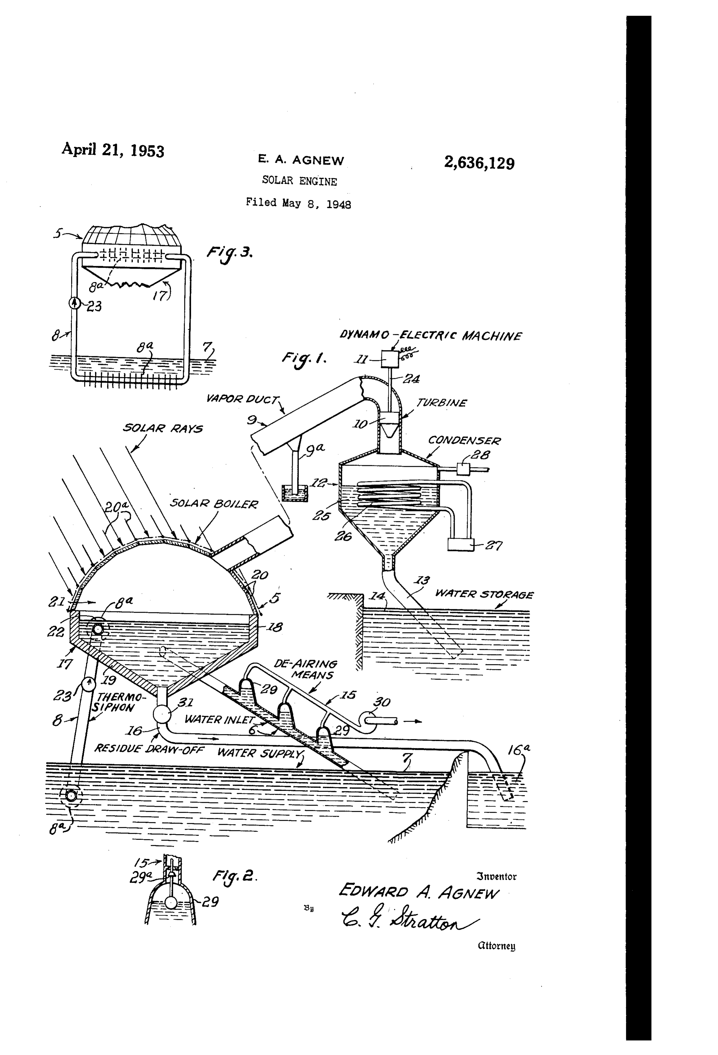
Fig. 2 is an enlarged sectional view of float The relatively large surface of Water 22 Will means employed in .the appara
Page 1drawing sheetscan →
Page 2scan →
Patented Apr. 21, 1953
United states patent office
Solar engine
Edward A. Agnew, Whittier, Calif.
Application May 8, 1948, Serial No. 25,920
This invention relates to apparatus, responsive 2 to the energy of solar rays, for functioning to: Fig. 3 is a Side view, to a reduced Scale, as seen from the left of Fig. 1.
1. Distill sea water to obtain the salt therefrom. The Solar engine that is illustrated comprises, 2. Refine and/or distill industrial plant water. generally, a Solar boiler 5, a water inlet and dif 3. Lift water to a higher elevation for use in ferential-pressure conduit 6 to said boiler from generating hydro-power. a reservoir or water supply 7, a thermo-Siphon 4. Lift potable Water for use at a higher eleva exchanger 8 extending from the reservoir 7 into tion than where stored. the Solar boiler, a duct 9 for vapors generated in 5. Generate electric power with solar energy. the Solar boiler and for conducting Said vapor 6. Refine and/or distill any liquid that exhibits to a high level and a remote point, turbo-electric the typical liquid-vapor cycle. means comprising a turbine O that is operated 7. Transport the energy of solar rays as desired. by the vapors moving in duct 9 and a dynamo 8. Obtain potable water from Sea, Water or from electric machine operatively connected thereto, an unpotable source. a condenser 2 for condensing Said vapors, a dif 9. Gather and store heat and/or energy for use ferential-pressure conduit comprising a discharge in the home, in industry, etc. f3 from the condenser to a water storage 4, It is an object of the present invention to pro means 5 for de-airing the water moving in the vide novel apparatus for accomplishing any inlet 6, and a residue draw-off 6 for the Solar and/or all of the foregoing phenomena. boiler 5.
Another object of the invention is to provide 20 The solar boiler 5 is located at a sufficient improved apparatus that utilizes the energy of height above reservoir So that inlet 6 may com Solar rays for effecting a temperature differential prise a differential-pressure conduit under con between a quantity of water or other liquid and ditions of minimum capacity of the reservoir. the atmosphere thereabove, to conduct the result Said boiler, when serving as a still for salt Water, ant vapors to a higher level, and to condense said 25 will have Such a capacity that the surface of the vapors and store the liquid thus provided. Water therein will approximate 50,000 Square feet Another object of the invention is to provide or approximately one acre. Accordingly, the apparatus as indicated wherein the vapors create boiler will comprise a hopper-like basin 7 con power to generate electric current. structed of reinforced concrete and supported at A further object of the invention is to provide the proper height by structural columns or piers Such apparatus whereby, also, a heat exchange 30 (not shown). The basin 7 is preferably of cir is effected between a source of water supply and cular form, the upper portion 8 thereof being a quantity of said water obtained from the supply cylindrica and the lower portion 9 conical with to increase vaporization of said quantity of water. its apex at the draw-off 6. The cylindrical por My invention also has for its objects to provide 35 tion 8 is formed of Such a height as to accord such means that are positive in operation, con With any variations in level of the reservoir to venient in use, easily installed in a Working posi maintain the Surface of the water in the boiler tion and easily disconnected therefrom, economi above the upper end of inlet 6. cal of manufacture, relatively simple, and of gen The basin T is completely covered or roofed eral superiority and serviceability. 40 by a plurality of glass panels 20 arranged in The invention also comprises novel details of spherically domed form to enclose a vaporizing construction and novel combinations and ar chamber 2 above the level 22 of water in basin . rangements of parts, which Will more fully ap The panels 20 are mounted in a suitable struc pear in the course of the following description. tural frame with compressible seats or gaskets to However, the drawings merely show and the foll 45 accommodate expansion. The outwardly facing lowing description merely describes one em Surfaces of the glass panels may be coated to bodiment of the present invention, which is given increase the transmission therethrough of the en by Way of illustration or example only. tire range of frequencies of solar rays. Certain In the drawings, like reference characters des nitrides have proven effective for this purpose. ignate similar parts in the several views. The above-described boiler is constructed to be Fig. 1 is a semi-schematic sectional view of 50 air-tight, the construction contemplating suit apparatus vention.
including features of the present in able seals around panels 20 and between the dome and the basin to effect the same.
Fig. 2 is an enlarged sectional view of float The relatively large surface of Water 22 Will means employed in .the appara
55 be subjected to the heat and energy in the solar rays passing through the coated panels 20 to 3 cause vaporizing of said water. As will herein Condensing of the vapors in condenser 2 is after be indicated, the chamber 21 is subjected induced by means such as a cooling coil 26 to pressure that is less than atmospheric. through which a pump 27 circulates a cooling The Water inlet or differential-pressure leg 6 medium. Free air in the vapors, entering the is preferably disposed at an angle to permit the 5 condenser, may be removed by a scavenging pump incorporation therein of the de-airing means 5. 28 to obviate the formation of an air pocket that Said leg extends from within the reservoir up may counter to the movement of vapors into the wardly to the basin 7 and connects into the condenser. In the main, the condenser, in de latter at a tangent to promote a mild circulation sign and capacity, may follow and include con in the boiler. It is evident that upon rarefication O ventional and accepted features of condenser de of the atmosphere in chamber 2 resulting from sign. The alkalinity-acidity constant of the the heat of the solar rays, water from the reser Water Collected in Storage 4 may be expresed by voir will pass up in inlet 6 to fill basin accord a pH of 9 and its hardness by Zero. ing to the differential of pressures. On the water In practice, the level of the water storage 4 in the reservoir and in the basin. 5 is elevated with respect to the level of reservoir The thermo-siphon 8 is provided for Supple 7. It is evident, therefore, that valuable power menting the vaporizing power of the Solar rayS. may be generated by returning the stored water Said thermo-siphon is of the gravity flow type of to its original level or other intermediate levels. sufficient capacity for establishing and main 20 ingThe de-airing means 5 is provided for remov taining a minimum continuous Operation. Said maya be large proportion of any free air or gas there in the Water paSSing upWardly in con thermo-siphon comprises a closed System of ducts that is filled with liquid which, because of a check duit 6. A plurality of inverted bells or domes valve 23 in one leg of the same, sets up a flow of 29 in Said leg are arranged to progressively trap said liquid in one direction only at a rate com Out more and more free gases, the same to be then drawn off by a suction pump 33. Each mensurate with the temperature differential of 25 done the Water in the reservoir and the Water in the 29, as shown in Fig. 2, may embody Suit solar boiler. When the water in reservoir is of able float Valves 29a that control the liquid level higher temperature than that of the Water in therein and thereby prevent liquid from passing the boiler, as during night time Operation, the 30 off through the de-airing means. Water in the boiler will be Warmed by an exchange It Will be evident that evaporation in the boiler of heat with the liquid flowing in the thermo will result in an increasingly larger proportion of siphon. Since check valve 23 closes to downward Solids in the water therein. Said solids, in the form of residue, can be drawn off, from time to flow in siphon 8 and opens only to upward flow, time, through draw-off line 6 by opening the the circulation of liquid in the siphon is always in one direction, said circulation being induced valve 3 in Said line. This residue contains in any by the mentioned temperature differential be valuable by-products that may be refined and/or tween water source 7 and boiler 5. Separated as desired. The line 6 may also con The duct 9 extends from the boiler 5, and more prise a differential-pressure conduit entering specifically from the domed roof thereof, at an 40 into a vessel 6a, that receives the residue. The operation of the Solar engine above de upward angle. Said duct is shown broken and offset to indicate an indeterminate length of the Scribed is as follows:
duct and elevation of the upper end thereof. Be Valve 3 is closed and the turbine O Set into cause of the large area of the boiling Water Sur operation by the dynamo-electric machine Op face 22 and the relatively smaller cross-sectional erating as a motor to cause partial exhaustion area of the duct, an hydraulic advantage results of the air in solar boiler 5. By atmospheric to cause acceleration of vapor rising from Said pressure, water from reservoir T will rise in con surface and moving in the duct. The accelera duit 6 and enter basin T. At the same time tion Would be a function of the ratio of Surface pump or pumps 28 will be started to exhaust the 22 to the cross-sectional area of the duct. Thus, air received in condenser 2. Thereafter, the the vapors move in duct 9 at a high rate of speed. pump 28 is controlled automatically to maintain Some heat loss in the vapors, resulting in Con the liquid levels in the boiler and Condenser. densate forming in the duct, may result. Ac Pump 30 is set into operation when flow condi cordingly, suitable liquid traps 9d may be pro tions are obtained.
vided for removing Such condensates. For long Under the influence of the energy in the Solar transmissions, the duct may be suitably heat in rays and/or the exchange of heat imparted by Sulated for improved efficiency. the thermo-siphon. 8, vaporization of the liquid The turbine 0 of the turbo-electric means is in the boiler will start as hastened by the rarefied positions either in the upper end of duct 9 or atmosphere in chamber 2. At this time cold otherwise Suitably to receive and be operated by 60 water circulation is started in condenser coil 26. the fast moving Vapors seeking egress from the As the rising vapor extracts heat from the duct. The turbine may be of velocity type which, boiler, the temperature of the water therein will through the medium of a connecting shaft 24, drop. This temperature drop, in turn, will start Operates the dynamo-electric machine as a generator. The latter, typically, generates elec 65 circulation of the liquid in the thermo-Siphon 8. This flow, in turn, will extract heat from tric current for Storage and/or transmission, as reservoir T. There is, therefore, set up two flows desired. of heat-One from the reservoir to the boiler After operating the turbine, the vapors will pass and another by solar radiation through the glass into condenser 2 to be condensed into a liquid roof 20. This heat Will be transferred from the that is collected at 25 and expressed through dis 70 Water in the boiler to the vapor therein and ex charge leg 3 into storage 4. It is evident that pressed in the amount described as the heat of Said liquid is free of any, except the most micro evaporation of the liquid.
Scopic, of the solids or bacteria, present in the The heated vapors will then pass, at an ac liquid taken from reservoir 7. If salt water is initially eSt.
used, potable water in storage 4 will 75 celerated rate, through duct 9 to operate turbine 0 and drive motor generator as a generator.
Page 4scan →
5 S
The condenser f2 will then condense the vapors 2. In a solar engine, a reservoir, a basin for and absorb the heat remaining therein,
If salt water is the initial liquid drawn into the pressure conduit extendingreservoir, receiving liquid from the from the a differential reservoir to boiler, after a period of time, the percentage of the basin for passing liquid into the latter, a salt and other solids will approach a density high 5 transparent dome for the basin and comprising a enough to warrant drawing the same off through plurality of flat line 6. This may be accomplished without in to evaporate thesheets for transmitting Solar rays liquid in the basin, a closed terrupting the process of evaporation.
The following two examples of the expected circuit from thermo-Siphon heat exchanger extending the reservoir and into the liquid in the operation of the solar engine Will show its ability O basin for increasing the evaporative rate of Said to perform the objects of the invention: liquid, an upwardly directed duct extending from said dome to conduct the evaporated liquid to a
Operation at 10 a.m. at Night level above and at a substantially lower atmos pheric pressure than that of both the reservoir 5 and the basin, a condenser at the upper end of
Temperature of Sea Water-------------- F -- 75 65
Internal Temperature of Boiler--------o
127 60 the duct to condense said vapors, means for re moving free air from the condenser, a storage
Condenser Temperature--- -- o F. 80 50 reservoir elevated above the first-mentioned res Liquid Transferred.--------------libs.
Efficiency----------------percent... 16 20 ervoir, and a differential pressure conduit leading from the condenser to the storage reservoir.
3. In a solar engine, a reservoir, a basin for
Such variations in the above figures that may receiving liquid from the reservoir, a differential occur can only refect on the efficiency of the pressure conduit extending from the reservoir to engine rather than on its mode of Operation. It the basin for passing liquid into the latter, a is assumed, however, that the ratio of night-to 25 transparent done for the basin and comprising a day operation will not exceed four to One. plurality of flat sheets for transmitting solar rays The apparatus herein described may be oper to evaporate the liquid in the basin, a duct ex ated to provide a refrigerating medium for many tending upwardly from said dome to receive uses. For such uses the apparatus may be Vapors generated in the basin and conduct them smaller in size than herein indicated. By either 30 to a relatively elevated level, the cross-sectional covering the panels 20 during Sunlight as by area of said duct being considerably smaller than movable vanes 200, or operating the engine dur the Surface area of the liquid in the basin. Where ing the night, and employing the dynamo-electric by the vapors nove upward in the duct at an machine as a motor to create suction in duct 9 accelerated speed, a condenser at the upper end of and vacuum in chamber 21, rapid vaporization of the duct for condensing the vapors entering the water in the boiler, resulting in considerable re Sane, turbo-electric means in the duct and on duction in the temperature of said water, results. the inlet side of the condenser and operated by Said low temperature water can then be used to the vapors inowing toward the latter, means to cool the Water in reservoir which may then be remove free air from the condenser, a storage used for refrigerating purposes. To increase this ...t) reservoir elevated above and under a lower pres cooling effect between the water in the boiler and Sure than the pressure on the first-mentioned in reservoir , the thermo-siphon 8 may be pro reServoir, and a differential conduit extending vided with fins 8d, to facilitate heat exchange be between the condenser and Said storage reservoir. tween the water in the thermo-Siphon 8 and the 4. In a solar engine, a reservoir, a basin for water in the reservoir T. receiving liquid from the reservoir, a differential While I have illustrated and described what I pressure conduit extending from the reservoir to now regard as the preferred embodiment of my the basin for passing liquid into the latter, a invention, the construction is, of course, Subject transparent dome for the basin and comprising a to modifications without departing from the plurality of flat sheets for transmitting Solar rays spirit and scope of my invention. I, therefore, do : to evaporate the liquid in the basin, a duct ex not wish to restrict myself to the particular form tending upwardly from said dome to receive va of construction illustrated and described, but pors generated in the basin and conduct them to desire to avail myself of all modifications that a relatively elevated level, the cross-sectional may fall within the scope of the appended claims. area of said duct being considerably smaller than Having thus described my invention, what I the surface area of the liquid in the basin where claim and desire to secure by Letters Patent is: by the vapors move upward in the duct at an 1. In a solar engine, a reservoir, a basin for accelerated Speed, a condenser at the upper end receiving liquid from the reservoir, a differential of the duct for condensing the vapors entering pressure conduit extending from the reservoir to the Same, turbo-electric means in the duct and the basin for passing liquid into the latter, means 60 On the inlet side of the condenser and operated in said conduit for removing free air in the liquid by the vapors moving toward the latter, said passing therethrough, a transparent dome for turbo-electric the basin and comprising a plurality of flat the duct and ameans comprising a turbine within sheets for transmitting solar rays to evaporate tively connected dynamo-electric machine opera therewith, means to remove free the liquid in the basin, an upwardly directed duct air from the condenser, a storage reservoir ele extending from said dome to conduct the evapo Wated above and under a lower pressure than the rated liquid to a level above and at a substantially pressure on the first-mentioned reservoir, and a lower atmospheric pressure than that of both the differential conduit extending between the con reservoir and the basin, a condenser at the upper denser and said storage reservoir. end of the duct to condense Said Vapol'S, means for removing free air from the condensei', a stor 5. In a solar engine, a reservoir, a basin for age reservoir elevated above the first-mentioned receiving liquid from the reservoir, a differential reservoir, and a differential pressure conduit preSSure conduit extending from the reservoir to leading from the condenser to the storage reser the basin for passing liquid into the latter, a Voir. transparent dome for the basin and comprising a 75 plurality of flat sheets for transmitting solar rays 5 to evaporate the liquid in the basin, a duct ex from entering therein, means for removing free air tending upwardly from said dome to receive va the condenser, a storage reservoir below the pors generated in the basin and conduct them to condenser and elevated substantially above the a relatively elevated level, the cross-sectional level of the water supply and at a lower atmos area of said duct being considerably smaller than pheric pressure than Said water Supply, and a the surface area of the liquid in the basin where differential pressure conduit leading from the by the vapors move upward in the duct at an condenser to said reservoir. accelerated speed, a condenser at the upper end 7. A solar engine according to claim 6: turbo of the duct for condensing the vapors entering electric means in the duct and on the inlet side the same, turbo-electric means in the duct and on 0 of the condenser and operated by the vapors moving toward the latter.
the inlet side of the condenser and operated by the vapors moving toward the latter, said turbo EDWARD A. AGNEW. electric means comprising a turbine within the duct and a dynamo-electric machine operatively connected therewith, said machine being adapted 5 References Cited in the file of this patent to be operated as a motor to drive the turbine to UNITED STATES PATENTS evacuate, through the duct, the atmosphere above Number Name Date the basin and within the dome and thereby 983,424 Brosius ------------- Feb. 11, 1911 hasten the evaporative rate of the liquid in the 995,219 Bradley------------ June 13, 1911 basin, means to remove free air from the COn 20 1,101,000 Willsie ------------- June 23, 1914 denser, a storage reservoir elevated above and 1,544,029 Nelson ------------- June 30, 1925 under a lower pressure than the pressure On the 2,030,350 Bremser ----------- Feb. 11, 1936 first-mentioned reservoir, and a differential con 2,167,576 Kiser -------------- July 25, 1939 duit extending between the condenser and Said 25 2,200,138 Von Sauer ---------- May 7, 1940 Storage reservoir. 2,213,894 Barry -------------- Sept. 3, 1940 6. A solar engine comprising, in combination, 2,372,846 Nettel et al. --------- Apr. 3, 1945 a water supply, a Solar boiler positioned above 2,424,142 Bimpson et al. ------ July 15, 1947 said supply and having a water-holding basin FOREIGN PATENTS wherein water may be evaporated by Solar rays 30 striking the boiler, a differential pressure conduit Number Country Date extending from the Water Supply to the basin for 11,511 Australia ---------- May 18, 1908 passing water from the former to the latter, a 28,130 Great Britain ------------ of 1907 duct extending upwardly from the boiler to con 763,867 France ------------ Feb. 19, 1934 duct water vapor from the boiler to a level OTHER REFERENCES Substantially above the Water Supply and the 35 Scientific American, February 1930, pages 144 boiler, a Vapor condenser at the upper end of said duct to receive and condense the water vapors and 145.
Provenance
- Collection
- Patents citing this work
- Pages
- 5
- Method
- pdftotext (the PDF's own text layer) + pdftoppm 300dpi page scans
- Patent office record
- patents.google.com →
- Source
- Google Patents citing-documents table
- Assignee
- Edward A Agnew
- Published
- 1953-04-21
- Transcribed from
- patentimages.storage.googleapis.com →