

patent · US3958553A
Solar energy trap
25 May 1976
Text
Page 1scan →
United States Patent (19)
Brantley, Jr.
54 solar energy trap
75) Inventor: Lott W. Brantley, Jr., Union Grove,
73 Assignee: The United States of America as represented by the Administrator of the National Aeronautics and Space
Administration, Washington, D.C.
52 U.S. Cl................................. 126/270; 126/271;
51) Int. C.’.................. ... ...................... F24J 3/02
United states patents
291,146 lf1884 Calver................................. 126/271 294,117 2/1884 Calver................................. 126/271 1951,403 3/1934 Goddard............................. 126/271 3,415,588 12, 1968 Berreman........................... 3501179 3,467,840 9, 1969 Weiner............................... 126/27
Foreign patents or applications
Primary Examiner-Kenneth W. Sprague
Assistant Examiner-James C. Yeung
Attorney, Agent, or Firm-Wayland H. Riggins; L. D. Wofford, Jr.; John R. Manning
An apparatus is provided for trapping solar energy emitted from the sun for heating a fluid that could be subsequently used in turbines and the like. The appa ratus includes an elongated vertical light pipe having an open end through which the visible spectrum of electromagnetic radiation from the sun passes to strike a tubular absorber carried adjacent the other end thereof. The light pipe has a coated interior surface of a low absorptivity and a high reflectivity at the visible wave lengths and a high absorptivity/emissivity ratio at infrared wave lengths. The tubular absorber has a coating on the surface thereof for absorbing visible wave lengths so as to heat the fluid passing there through. Infrared wave lengths are radiated from the tubular absorber back into the light pipe for heating fluid passing through a tubular coil wound thereon. 4 Claims, 3 Drawing Figures
Drawings
Page 2drawing sheetscan →
Page 3drawing sheetscan →
Page 4scan →
relationship with the coated surface for heating the
Accordingly, it is an important object of the present
ORIGIN OF THE INVENTION invention to provide an efficient apparatus for absorb ing the visible spectrum of electromagnetic radiation
The invention described herein was made by an em generated ployee of the United States Government and may be by the sun.
manufactured and used by or for the Government for toAnother provide important object of the present invention is a solar energy absorber which has no moving governmental purposes without the payment of any royalties thereon or therefor. parts and is simple to construct.
10 Still another important object of the present inven
BACKGROUND OF THE INVENTION tion is to provide a solar energy absorber which gradu This invention relates to a solar energy absorber and ally heats an incoming fluid to a predetermined temper more particularly to a solar energy absorber which ature.
traps the visible spectrum of electromagnetic radiation 15 tionStillis another important object of the present inven provide a solar energy absorber which traps for heating a fluid.
Heretofore, most systems designed to trap solar en solar energy which would otherwise be radiated back to the atmosphere producing a highly efficient solar en ergy utilized a system often called “the green house ergy absorber.
effect." In such systems, visible radiation passes through one or more transparent outer covers and is 20 tion is another
Still important object of the present inven almost entirely absorbed by an absorptive surface. The coupledtotogether provide a solar energy trap which can be absorptive surface was usually constructed of tubing heated liquid. with other traps to produce a super wherein a fluid must pass therethrough for transferring These and other objects will become more readily thermal energy absorbed by conduction. The outer apparent cover, while transparent to visible radiation is largely 25 attendant from reading the following specification and claims.
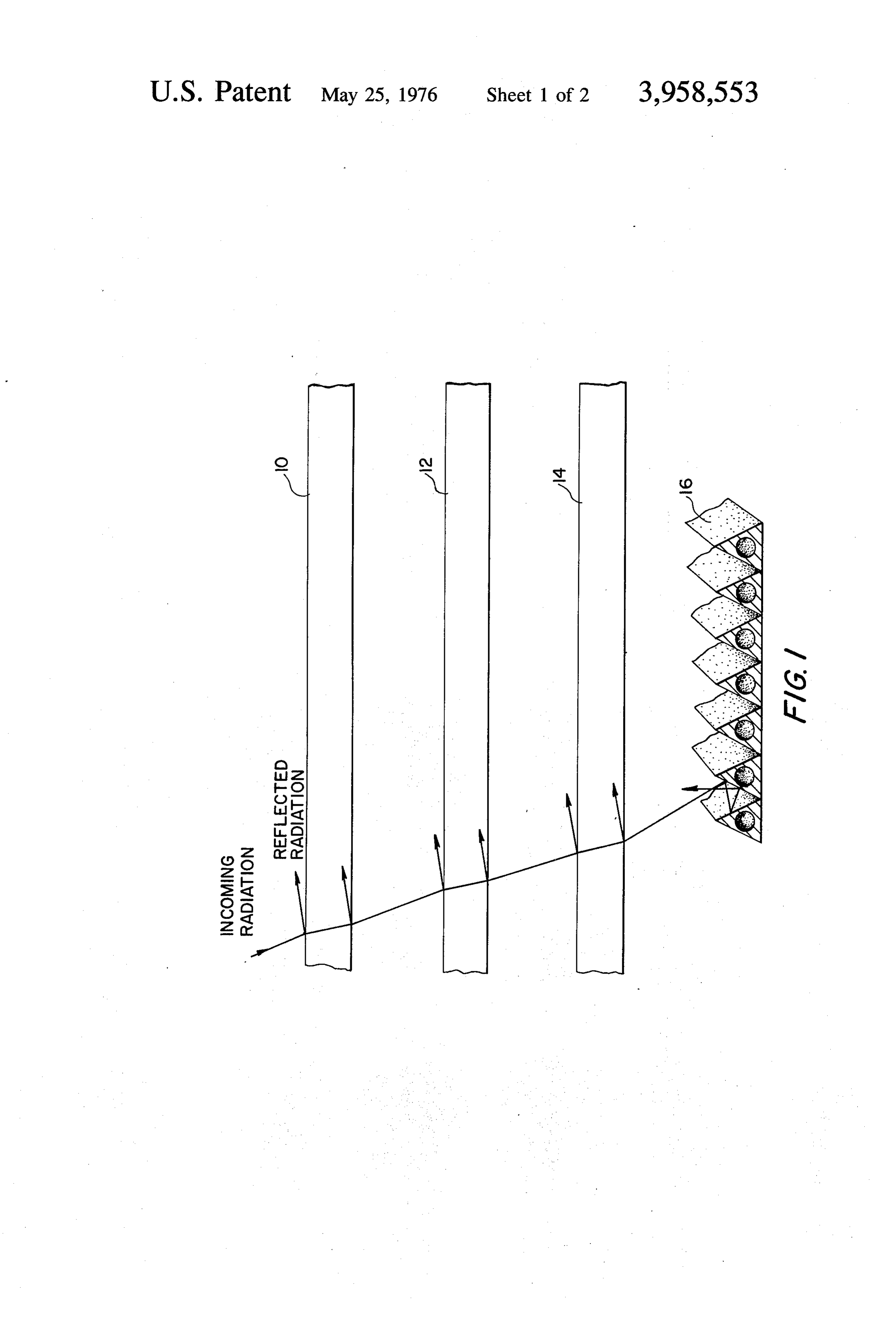
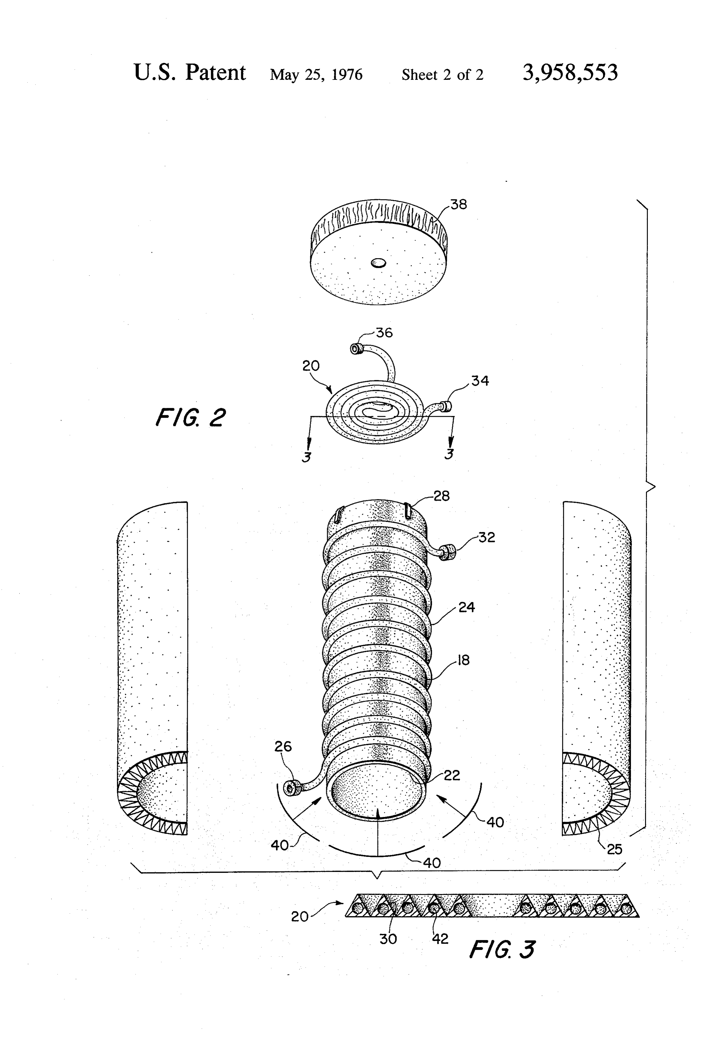
opaque to infrared radiation off of the absorber sur face, and hence, absorbs it. It conducts the energy that BRIEF DESCRIPTION OF THE DRAWING is not re-radiated to the absorber surface through the FIG. 1 of the drawing is a schematic diagram illustrat outer cover where it is convected or re-radiated away. ing a conventional solar energy absorber, Examples of such a system are shown in U.S. Pat. No. 30 FIG. 2 is an exploded perspective view illustrating a 1,258.405 and U.S. Pat. No. 2,969,788. solar energy trap constructed in accordance with the For a given absorptive surface, the amount of energy present invention, and lost by convection and infrared radiation is a function FIG. 3 is a sectional view taken along line 3-3 of of the outer cover temperature. Often more than one FIG. 2.
outer cover is used to reduce the infrared energy reach 35 ing and, consequently, heating the final cover. DESCRIPTION OF THE PREFERRED The use of transparent covers, as described, is not EMBODIMENT. without its penalties however, in a practical absorber Referring in more detail to FIG. 1 of the drawings, system design. The transparent covers reflect some there is illustrated a portion of a conventional solar incoming radiation away before it gets to the principal 40 energy absorber. The solar energy absorber includes absorptive surfaces. It also absorbs some of the incom three glass plates 10, 12 and 14 stacked one above the ing visible radiation. The transparent covers are usually other with a vacuum or air layer carried therebetween. of a brittle material, glass or quartz. Such are conse Directly below the lower glass plate 14 and spaced quently hard to handle in assembly and maintenance. therefrom is an absorber member 16. The absorber Dust adhering to such a cover increases losses. 45 member 16 may be constructed of triangular shaped Another problem with the transparent covers is that tubing coated to absorb the visible spectrum of electro if the temperatures rise above a predetermined level, magnetic radiation. Fluid passes through the tubular such will often be damaged by breaking or the like. member 16 for transferring the thermal energy ab SUMMARY OF THE INVENTION sorbed thereby. One problem with the solar energy 50 absorber shown in FIG. 1 is that since the visible spec
It has been found, in accordance with the present trum of the electromagnetic waves have to pass invention, that an effective solar energy trap can be through the three layers of glass, 10, 12 and 14, a cer constructed for converting the electromagnetic radia tain amount thereof is reflected affecting the efficiency tion emitted from the sun into thermal energy for heat of the overall system. Another problem with the system ing a fluid. The apparatus includes an elongated tubular 55 is that as the energy passes through the glass layers 10, light pipe having open ends and positioned so as to 12 and 14, a certain amount of the energy is absorbed receive the solar radiation waves through one end. A also affecting the efficiency of the system. When dust reflective coating is provided on the interior surface of collects on the glass layers 10, 12 and 14 this problem the light pipe having a low a (absorption factor) for the 60 is enhanced.
visible electromagnetic spectrum and a high a for the Theoretically, in the device shown in FIG. 1, addi infrared electromagnetic spectrum to effectively direct tional glass layers could be stacked one above the other the incoming visible radiation towards a tubular ab so as to minimize the amount of infrared radiation loss. sorber coil carried on the opposite end of the light pipe. However, as additional layers are added, such cuts The tubular absorber has a coated surface character 65 down on the amount of the visible spectrum of electro ized by a high a value and a low e value for absorbing magnetic radiation passing therethrough to reach the the visible electromagnetic spectrum and for conver ultimate solar energy absorber.
sion of the visible radiation into thermal energy. Fluid Referring now to FIG. 2, there is illustrated a solar is conveyed through the tubular coil in heat exchange energy trap which includes an elongated tubular pipe
Page 5scan →
18. While in this particular application, the tubular for Selectively Absorbing Solar Thermal Energy and shape of the pipe is cylindrical, it is to be understood the Method for Manufacturing the Panel,' filed in the that in many applications, it may be desirable to make name of James R. Lowery, which consists generally of the tubular shape of the pipe square so as to permit an aluminum substrate coated with a zinc layer having positioning of a plurality of pipes closely adjacent to a bright nickle surface thereon with a highly absorptive each other in a given area. So as to direct and reflect black nickel plated thereon.
the Solar energy passing through the open end of the An outlet end 32 of the tubular pipe 24 which ex bottom of the pipe to an absorber, designated generally tends around the light pipe 18 may be connected to an at 20, carried on top of the pipe, an inner surface 22 of 10 outer inlet end 34 of the tubular pipes which are coiled the light pipe. 18 is coated with a surface having a low to form the absorber. In this case, as can be seen in Solar energy absorbing coating which means the coat FIG. 2, an inner end 36 of the solar spectrum absorber ing is characterized by a low absorption factor (cy). The coil 20 forms the final outlet for fluid flowing through surface coating is further characterized by its o?e ratio the end 32 of the tubular pipe 24. In the alternative, a where a is the absorption factor for solar radiation and fluid may be pumped separately through tubular pipe e is the infrared emissivity factor. The significance of 5 24 and tubular absorber 20 so as to produce a low the cyfe ratio is that the higher the o?e ratio, the more temperature and high temperature fluid, respectively, cfficient the surface coating is for absorbing solar radi using conventional pump means. As fluid passes from ation and the less efficient it is for emitting (or absorb the inlet end 34 of the coil 20, it is heated progressively ing) infrared. Therefore, the surface coating 22 must higher so that the fluid reaches its highest temperature have a low solar radiation absorption factor, hence a at the center of the coil 20 which is also at the outlet 36 low or and for reasons to be discussed later, a high of the tube. This is for two reasons. One being that a infrared radiation absorption factor, hence a high e. greater concentration of the solar energy passing The actual material used will vary depending on the through the light pipe strikes adjacent the center of the actual temperatures at which the apparatus is designed absorber 20 rather than adjacent the edges. Another to operate. In one particular embodiment, a surface 25 reason being that the pipe is in a coil configuration and coating designed by the ALCOA Company and mar as the fluid passes from the outer surface towards the keted under the trademark Alzak is utilized. This mate interior thereof, it is also heated a certain extent by rial has an a of 0.28 and an e of 0.78. The light pipe conduction. In order to prevent escaping of thermal configuration, length to diameter ratio, may be varied. 30 energy from the absorber 12, a circular layer 38 of For large ratios, infrared losses are minimized, but that fiberglass insulation is attached to the top side of the ratio of energy available in the preheater, which in absorber 20.
cludes the portion of the apparatus including the light In operation in order to multiply the effect of the pipe 18, compared to that available in the absorber 20 sun's rays a plurality of mirrors 40 are mounted circum is raised, especially for off-axis incoming radiation and ferentially around the lower end of the solar energy light pipe materials with relatively low reflectance. In 35 trap for directing the visible spectrum of the electro one particular embodiment, the ratio of the length of magnetic radiation produced by the sun upward the light pipe to the diameter is three to one. The light towards the longitudinal axis of the light pipe. Some of pipe has a length of twelve inches and a diameter of the waves strike the inner surface 22 of the light pipe four inches. In essence, by increasing the length of the 40 and are reflected upwardly to eventually strike the light pipe 18, such permits more energy to be absorbed absorptive surface 30 of the absorber 20. Depending on by the light pipe as a result of the reflection taking the angle of the incoming waves, a certain percentage place therein decreasing the ultimate amount that of the waves strike the absorber 20 directly. As can be reaches the absorber 20. seen, one advantage of the particular apparatus dis Coiled around the outer surface of the elongated 45 closed is that these waves generated by the sun engage light pipe 18 is a tubular coil 24 which extends from the absorber without passing through any glass or the adjacent the top of the pipe to the bottom thereof. A like. As the electromagnetic waves engage the surface good thermal bond is provided between the tubular 30 of the absorber, thermal energy is transferred to pipe 24 and the light pipe 18 such as by welding or fluid flowing through the tubes extending therethrough. braising the tubular pipe 24 to the surface of the light As a result of the triangular shape of the surfaces 30, as pipe 18. In one particular application, the tubular pipe 50 best shown in FIG. 3, any waves that are not initially 24 is constructed of aluminum. A layer of fiberglass absorbed by the absorber 20 are reflected to engage an insulation 25 encircles the light pipe and tube 24 for adjacent surface for increased absorption. Cylindrical minimizing the amount of thermal energy lost from a bore 42 is formed within the triangular tube of absorber fluid passing through the tubular pipe 24 that is being 55 20 for conveying the fluid therethrough in a heat ex heated. The fluid is circulated through pipe 24 using changing relationship with the absorber. conventional pump means connected to an inlet 26. The infrared waves that are generated by the ab The solar spectrum absorber 20 may be attached to sorber are directed downwardly towards the surface 22 the top open end of the light pipe 18 by any suitable of the light pipe 18. Due to the particular coating 22 on means such as clamps 28. The solar spectrum absorber 60 the light pipe having a high infrared absorption factore, 20 is constructed of a coil of triangular tubular pipe these infrared waves are absorbed by the light pipe such as best illustrated in FIG. 3. It has a high solar preheating the fluid passing through the wound coil 24. energy absorbing coating 30 on the surface thereof. Also as a result of the absorber being on top of the light Hence, the absorptive coating is characterized by a pipe, thermal energy tends to concentrate adjacent the high a value (making it a good absorber of the visible 65 upper end thereof providing adjacent heating through spectrum of electromagnetic radiation) and a low e convection to the portion of the coil 24 adjacent the value (making it a poor thermal emitter). top of the light pipe. Thus, as can be seen, the light pipe One suitable surface is described in United States acts as a trap for solar radiation; permitting the passage Patent application, Ser. No. 458,484, entitled "A Panel of the visible spectrum of electromagnetic radiation 6 initiated by the sun to engage the absorber 20, while a heat exchanging relationship with said light pipe absorbing the major portion of any resulting infrared for permitting said thermal energy to be absorbed radiation into the interior surface 22 of the light pipe. by said fluid;
It is to be understood that the terms solar radiation e. absorber means comprising a substantially planar and electromagnetic radiation have been used inter tubular coil for conveying said fluid carried on said changeably to refer to the energy or radiation emitted open end of said pipe opposite to said open end for by the sun, however, the apparatus disclosed in accor receiving said radiation waves therethrough; said dance with the invention may also be used to trap and absorber means including a coated surface having a absorb energy emitted from other bodies as well. high absorption factor for absorbing the visible While a preferred embodiment of the invention has 10 portion of the electromagnetic radiation spectrum been described using specific terms, such description is of said radiation waves and for conversion of said for illustrative purposes only, and it is to be understood radiation waves into thermal energy; that changes and variations may be made without de f, said tubular coil encircling said light pipe being parting from the spirit or scope of the following claims. 5 connected to said coil of said absorber means; What is claimed is: g. whereby the light pipe acts as a trap, directing the 1. A solar energy trap for trapping and absorbing visible portion of the electromagnetic radiation electromagnetic radiation waves emitted from the sun spectrum to said absorber means for conversion and for converting the radiation waves into thermal therein to thermal energy to be absorbed by said energy for heating a fluid comprising: 20 fluid conveyed in heat exchange relationship with a. a source of fluid; said absorber means.
b. an elongated tubular light pipe having opened ends 2. The solar energy trap of claim 1 wherein the diam and positioned so as to receive said radiation waves eter of said planar tubular coil of said absorber means through one end thereof; is substantially as large as the diameter of said light pipe c. a highly reflective surface coating provided on the 25 at said open end at which said absorber means is car interior surface of said light pipe, said surface coat ried.
ing having a low absorption factor for the visible 3. The solar energy trap of claim 1 including a plural portion of the electromagnetic radiation spectrum ity of mirrors mounted circumferentially around said and having a high absorption factor for the infrared open end of said light pipe for receiving radiation portion of the electromagnetic radiation spectrum 30 waves therethrough, whereby said mirrors direct said for reflecting said visible portion and for absorbing radiation toward the longitudinal axis of said pipe. infrared radiation generated within said energy 4. The solar energy trap of claim 1 further comprising trap for conversion into thermal energy by said a layer of insulation surrounding said tubular coil encir light pipe; cling said light pipe for reducing the loss of thermal d. a tubular coil having a plurality of spaced turns 35 energy from said fluid. ck cK sk encircling said light pipe, for conveying said fluid in
Provenance
- Collection
- Patents citing this work
- Pages
- 6
- Method
- pdftotext (the PDF's own text layer) + pdftoppm 300dpi page scans
- Patent office record
- patents.google.com →
- Source
- Google Patents citing-documents table
- Assignee
- The United States Of America As Represented By The Administrator Of The National Aeronautics And Space Administration
- Published
- 1976-05-25
- Transcribed from
- patentimages.storage.googleapis.com →