

patent · US2867270A
Vaporizing type oil burner
6 January 1959
Text
Drawings
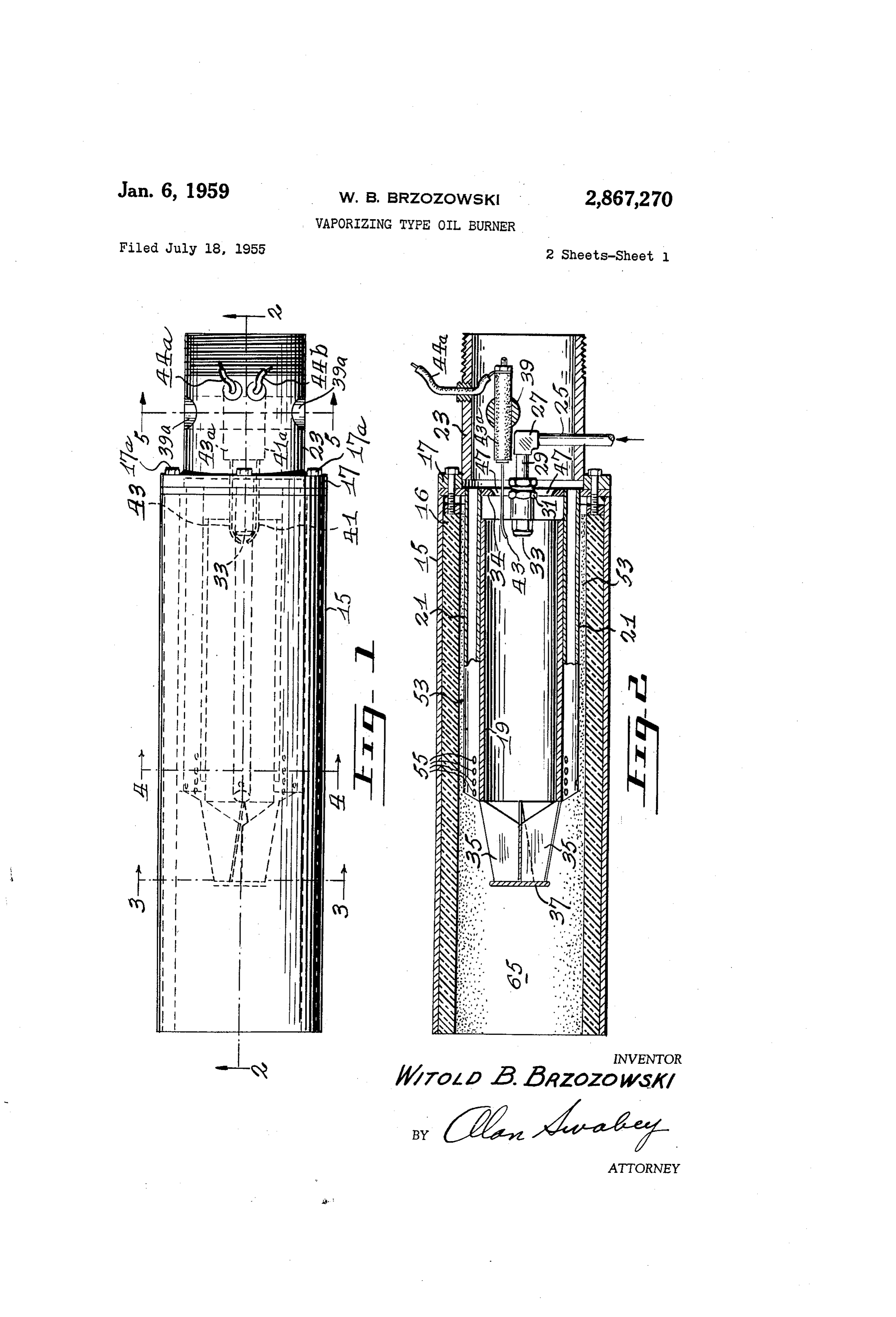
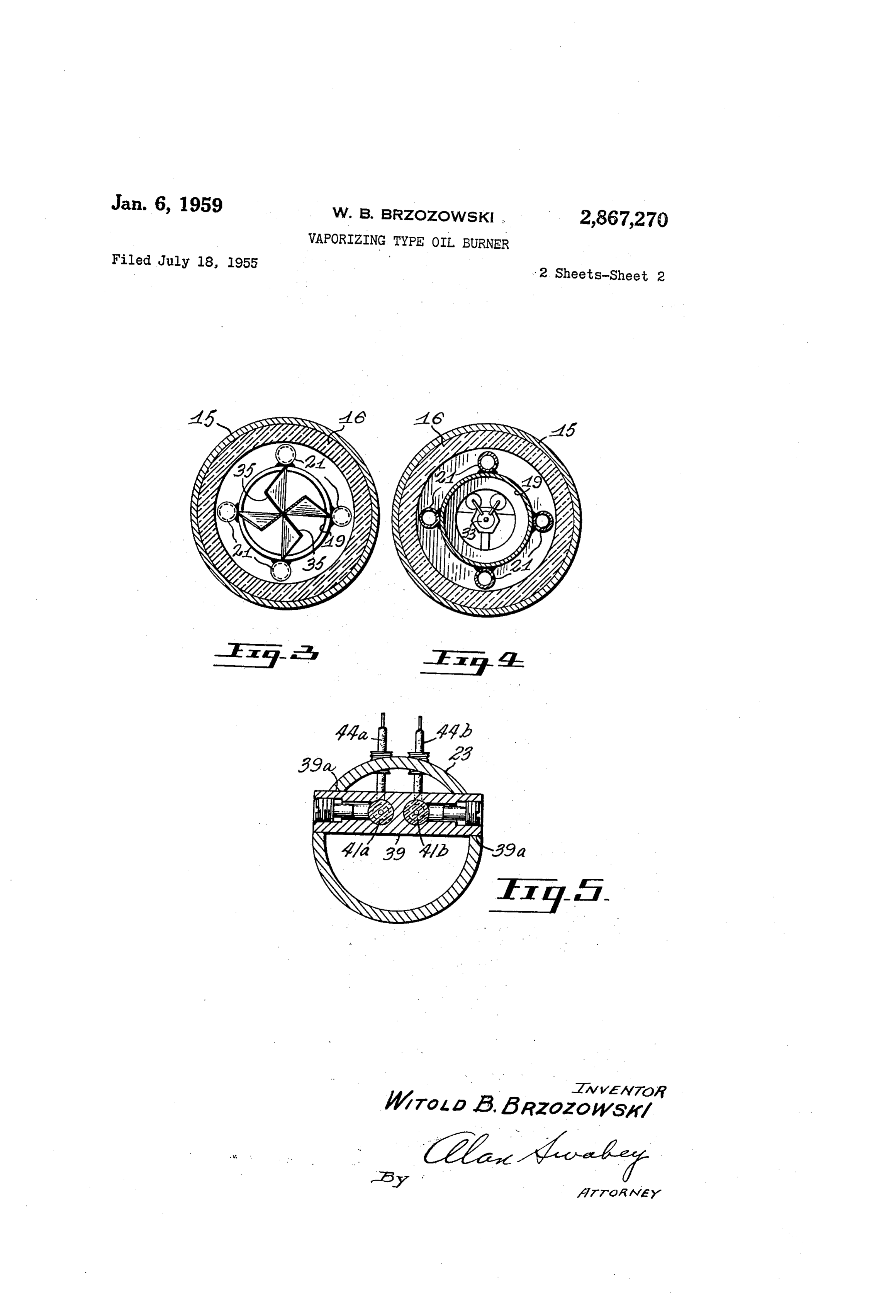
Figure 1 is a top plan view of the preferred form of burner according to the invention.
Figure 2 is a vertical cross-section along the line 2-2 of Figure 1.
Figure 4 is a transverse vertical cross-section along the
Page 1drawing sheetscan →
Page 2drawing sheetscan →
Page 3scan →
United States Patent Office Patented Jan. 6, 1959
Figure 1 is a top plan view of the preferred form of burner according to the invention.
Figure 2 is a vertical cross-section along the line 2-2 of Figure 1.
2,867,270 Figure 3 is a transverse cross-section along the line VAPORZING TYPE OLBURNER 3-3 of Figure 1.
Figure 4 is a transverse vertical cross-section along the
Witold B. Brzozowski, Montebel?o, Quebec, Canada line 4-4 of Figure 1. - Application July 18, 1955, Serial No. 522,701 Figure 5 is a transverse vertical cross-section along the O line 5-5 of Figure 1.
3 Claims. (Cl. 158-76) Referring more particularly to the drawings, the burner is made up of a main burner tube 15 which is of metal lined with a refractory lining 16.
Within the main burner tube 15 and extending from the
This invention relates to vaporizing-type oil burners. 5 toward inlet end (at the right-hand side of Figures 1 and 2) According to the invention, there is provided the com the outlet end is a mixing tube 19. bination with air-supply means, vapor-fuel supply means thirds The tube 19 stops short in the form shown about two and ignition means of a burner tube and a mixing tube of the way into the burner tube. receiving air from the supply means and so arranged that 20 tube 17 is a header connected to the inlet end of the burner hot gases from a combustion chamber are recirculated 15 as shown by bolts 17a. The header carries cool between the mixing tube and the combustion tube to the ing-air pipes 21 which are connected to the sides of the inlet end of the mixing tube in a constant cycle. Ad mixing tube 19 about its periphery as shown. The tube ditionally, means are provided for cooling the end of the 19 is supported by the pipes 21 with its inlet end spaced mixing tube. This may take the form of conduits for 25 from the header 17 leaving a gap 34 between the inlet end of the tube 19 and the header.
carrying relatively cool air to the outlet end of the mix The header also mounts a blast box 23 which extends ing tube. in the direction opposite from the burner tube 15 and More specifically, in accordance with the invention, an elongated, preferably cylindrical, combustion tube is pro mixing tube 19. ? The header is provided with a central orifice 47 which vided. The inlet end of this tube carries a header. On 30 leads into the burner tube 15 at a central location so that the header is mounted a mixing tube which is also pref air from the blast box 23 is directed straight into the in erably cylindrical and has an inlet end, spaced from the terior of the mixing tube 19. header, to provide access from the space between the A nozzle arrangement made up of a pipe 25 extends burner tube and the mixing tube to the inlet end of the upwardly through the wall of the blast box 23 to an elbow mixing tube.
In one construction there are mounted on the header 35 27 to which is connected forwardly extending pipe 29 and preferably supporting the mixing tube a number which An mounts a nozzle holder 31, carrying a nozzle 33.
electrode arrangement for ignition is mounted and of cooling-air tubes which extend from the header and constructed as follows. It has a circular housing 39 are connected to the outer sides of the mixing tube and extend to positions near the outlet end of the mixing 40 which extends across the blast box 23 as best shown in Figure 2 and the circular housing 39 is carried in open tube. On the header, at the side opposite the burner tube, is mounted a blast box which extends in the direction op ingsMounted 39a in the wall of the blast box 23. posite to that of the burner and mixing tubes. The respectively inaretheelectrode housing 39 in openings 41b and 43b insulators 41a and 43a re header is provided with a central opening which leads spectively which carry the electrodes 41 and 43. Wiring from the blast box to the burner tube directly in line with the inlet end of the mixing tube. The cooling-air 44a and 44b extends from the electrodes 41 and 43 to the pipes receive their air from the blast box and convey ignition coil.
At the forward end of the vaporizing tube 19 is a mixer .
it to outlets in these pipes which are adapted to direct the made air tangentially onto the end of the mixing tube which the endupofofthe four mixing vanes 35 and a mixing plate 37 at mixing vanes.
serves to cool the end of the mixing tube and so prevent its disintegration by excessive heat. 50 Operation Also provided in the combination, is an atomizing In operation, air comes from the blower into the blast nozzle which extends near the inlet end of the mixing tube box. 23. This air passes partly through the opening or and means connected with the nozzle for supplying oil under pressure. Electrode means are provided for ignit air orifice and partly into the pipes 21 surrounding the ing the combustion mixture. 55 mixing tube 19. ( In a preferred form of the invention, this electrode means Ignition takes place at the end of the nozzle 33 by means is made up of a holder which extends cross-wise to vaporized of the electrodes 41 and 43. The liquid fuel is the blast box and is held therein and a pair of electrode within the tube 19 and mixed by the vanes 35 insulators which are held in orifices in the electrode holder and the plate 37 so that combustion takes place in the and extend forward and electrodes project forwardly from 60 passes through the burner portion 65 of the tube 15. Cool air meanwhile tubes 21 and is projected through the the insulators to within access of the nozzle.
The mixing tube is provided at its outlet end with a openings ing it.
55 on the end of the mixing tube 19, thus cool number of vanes and a mixing plate. The vanes and plate are adapted to cause turbulence in the vaporized oil 53 Hot gases are sucked back along the annular passage and air emerging from the mixing tube, causing it to be 65 faceformed between the refractory lining 16 and the outer of the tube 19 and constituting a circulation chamber.
mixed. These hot gases pass through the gap 34 and circulate Detailed description back again into the mixing tube 19.
Having thus generally described the invention, it will The hot gases in the spacial corridor 53 heat the walls now be referred to in more detail by reference to the ac 70 droplets the mixing tube 19 and a portion of the atomized companying drawings which illustrate a preferred embodi This oil ofvapor oil are vaporized by contact with the wall 19. is mixed with the air, and final mixing ment, and in which:
Page 4scan →
takes place at the mixer by the vanes 35 and the mixing the burner tube constituting with the space between the plate 37 and this mixture is thrown outwards and for inlet end of the mixing tube and the baffling member a wards into the combustion chamber 65 where combus tion takes place. - return passage for gases to return from the outlet end The cooling pipes 21 meanwhile convey air along the cooling of the mixing tube to the inlet end of the mixing tube, the side of the mixing tube. 19 to the orifices 55 and project tubes having at their outlet ends a plurality of this air tangentially onto the surface of the mixing tube. the mixingleading openings tangentially onto the outer surface of tube whereby the end of the mixing tube is 19. as shown for example in Figure 3, thus cooling the end portion of the tube to prevent it from being over cooled heated.
by fresh air.
2. A vaporizing oil burner as defined in claim 1 in
As the cool air comes out of the orifices 55, it becomes cluding electrical means adjacent to said fuel atomizing mixed with the hot gases entering the space between the means for igniting the atomized oil mixture. cooling tubes and surrounding the tube 19 and thus re 3. A vaporizing oil burner comprising in combination duces the temperature of the recirculated portion of the let a refractory-lined main burner tube having inlet and out gas passing through the space 53 and entering the gap having ends, a mixing tube mounted in said burner tube and 34 into the mixing tube. an inlet end adjacent to the inlet end of the burner tube and an outlet end spaced from the outlet end of the
Advantages burner tube, a header mounted on the inlet end of the : Advantages of this type of burner over other types of burner tube and spaced from the inlet end of the mixing gun burners are as follows. tube, the outside surface of the mixing tube and the in Very high rates of combustion can be achieved. Nearly 20 tube side of the burner tube and the inlet end of the mixing and the header forming therebetween a recirculation one hundred times more B. t. u./cu. ft. of combustion passage leading from the outlet end of the mixing tube space/hr. than with conventional burners. to the inlet end thereof, a plurality of cooling tubes of By the same token, the combustion space in any heat relatively small diameter mounted on the header and exchanger equipped with this type of burner will be con 25 spaced apart about the outer surface of the mixing tube siderably reduced.
An inert atmosphere can be obtained if desired. The and extending longitudinally thereof, the cooling tubes being connected to the mixing tube and forming a mount unit can burn with practically no excess air, thus produc ing ing high flame temperature. therefor, the cooling tubes being provided with open The burner produces a sootless blue flame which is an 80 ings adjacent to the outlet end of the mixing tube, means economy factor. - for supplying air to the cooling tubes and mixing tube, means for providing atomized fuel at the inlet end of
The flame. is short which is a great advantage where the mixing tube, means for igniting the fuel-air mixture, concentrated heat is required. the buriaer and mixing and cooling tubes being so ar The burner can operate under high pressure. This in ranged to cause the air-fuel mixture ignited at the inlet turn produces high velocity combustion products, thus 35 end increasing the heat transfer coefficient. The heating sur ing tube intomixing of the tube to be projected through the mix the burner tube while cooling air is blown faces are reduced as compared with conventional burn through said cooling tubes, and to draw a portion of the I claim: products of combustion back through the recirculation passage and between the inlet end of the mixing tube and 1. A vaporizing oil burner, comprising in combination, 40 the a refractory-lined main burner tube, a blast box at one through header by suction created by the forward rush of air end of said tube to provide blast air for combustion, a the mixing tube, thereby to recirculate a portion baffling member connected to and intervening said blast of the products of combustion into the stream of newly box and burner tube, a plurality of cooling tubes mounted ignited oil-air mixture.
on said baffling member and each having an inlet end 45 References Cited in the file of this patent adjacent to said blast box to receive air therefrom and an UNITED STATES PATENTS .. . outlet end within said burner tube remote from said blast box but spaced from the opposite end of the burner tube, 1,614,359 Gaston -------S S LSSSSS SS SS SSS S Jan. 11, 1927 said cooling tubes also being spaced from the wall of 1,718,732 - i Danforth -------------- ----- June 25, 1929 said burner tube, a mixing tube supported by said cooling 50 975?1033, .. .Wolff -------------------------- Sept ,25 1934 tubes and extending from a point spaced from said baffling 2,200,278 ... Johnston --------------- May 14, 1940 member to a point near the end of said cooling tubes, 2,220,603 Hirtz et al. ------------- Nov. 5, 1940 said baffling member having a centrally located opening 2,404,647 .... McCollum ------------------------ July 23, 1946 forming a passage leading from the blast box to the mix 2,424,765 McCollum :----------------- July 29, 1947. ing tube, fuel atomizing means for supplying atomized 55 2,549,347 • Van Tuy} -.-.-.-.-.-.-.-.-.-.-.-.-.- Apr. 17, 1951 liquid fuel at the inlet end of the mixing tube, the mixing 2,587,140 . . . Gorshkoff-------------------- Feb. 26, 1952. tube constituting a chamber within which atomized fuel 2,670,032 Vignere –--------------- Feb. 23, 1954 is ignited and projected forward into said combustion tube, 2,701,608 Johnson ---------------- Feb. 8, 1955 the space between the outside of the mixing tube and 2,716,330 Way ------------------ Aug. 30, 1955
Provenance
- Collection
- Patents citing this work
- Pages
- 4
- Method
- pdftotext (the PDF's own text layer) + pdftoppm 300dpi page scans
- Patent office record
- patents.google.com →
- Source
- Google Patents citing-documents table
- Assignee
- Witold B Brzozowski
- Published
- 1959-01-06
- Transcribed from
- patentimages.storage.googleapis.com →