

patent · US4085719A
Vapor pressure regulator for a vaporized liquid fuel system
25 April 1978
Text
Page 1bibliographic recordscan →
United States Patent (19)
Hamburg et al.
VAPOR PRESSURE REGULATOR FOR A
WAPORIZED LIQUID FUEL SYSTEM
Inventors: Douglas R. Hamburg, Birmingham;
Dante S. Giardini, Dearborn, both of
Mich.
(73) Assignee: Ford Motor Company, Dearborn,
Mich.
(51) Int. Cl. .............................................. FO2B 43/00 52 U.S. Cl. ................................ 123/122 E; 137/177;
1,871,302 8/1932 Carroll ................................. 123/133 2,394,401 2/1946. Overbeke .......................... 220/85 B 2,849,150 8/1958 Tompkins, Jr. ... 220/85 VR 3,306,273 2/1967 Dolphin ............................... 123/133 3,903,708 9/1975 Mair .............. ... 220/85 VR 3,948,224 4/1976 Knapp et al. ............................ 123/3
FOREIGN PATENT DOCUMENTS
159,044 6/1940 Germany ................................. 123/3 Primary Examiner-Charles J. Myhre
Assistant Examiner-Tony M. Argenbright
Attorney, Agent, or Firm-Robert A. Benziger; Keith L. Zerschling
A vapor reservoir adapted for use in conjunction with a vaporized liquid fuel system for an internal combustion engine is disclosed. The reservoir includes a movable wall member cooperative with means defining a hous ing to establish a variable volume vapor storage space. The movable wall member is referenced to the pressure of the air immediately upstream from the intake to the air and fuel metering portion of the engine. The housing includes a generally downwardly depending conden sate collecting and return section. Vapor delivery con duits are positioned within the housing and support a thermally floating finned member operative to disperse vapor delivered to the vapor reservoir. The movable wall member is provided with position sensing means operative to provide an input to an electrical circuit for controlling the rate of vapor delivery to maintain a predetermined quantity of vapor within the vapor space.
The electronic circuitry is operative to control a liquid fuel delivery means to provide quantities of liquid fuel to a liquid fuel vaporizer for charging the vapor storage space of the vapor reservoir. The electrical circuit is operative to vary a threshold voltage in response to the sensed position of the movable wall member. The vari able threshold voltage is compared to a saw tooth wave train to generate a variable duration voltage pulse in order to selectively control the coarse liquid fuel deliv ery means.
5 Claims, 3 Drawing Figures
Drawings
Page 2drawing sheetscan →
Page 3drawing sheetscan →
Page 4scan →
The mass of fuel required to be delivered to an inter
WAPOR PRESSURE REGULATOR FOR A nal combustion engine may vary over mass flow rates of VAPORIZED LIQUID FUEL SYSTEM about 20:1. It will be appreciated that a vapor reservoir CROSS REFERENCE TO RELATED for a vaporized liquid fuel system could, on the one APPLICATION hand, be designed to store adequate quantities of vapor ized liquid fuel under the extreme fuel consumption
This application is related to copending commonly conditions. However, this approach could result in an assigned patent application Ser. No. 660,281 filed on unnecessarily large accumulation of vaporized liquid Feb. 23, 1976 in the names of J. E. Auiler et al. and titled fuel within the reservoir. Furthermore, since the con "Vaporized Liquid Fuel Delivery and Metering Sys 10 ventional liquid fuel is gasoline which may be expected tem'. to be completely vaporized at temperatures of about BACKGROUND OF THE INVENTION 425 F., it will be appreciated that a vapor reservoir designed to maintain excessively large quantities of
The present invention is directed to the field of inter liquid fuel in vaporized form would have to be heated to nal combustion engine fuel delivery and metering sys 15 a relatively high temperature in order to avoid the con tems. In particular, the present invention is directed to densation and accumulation of condensed fuel. It is that portion of the above-noted field which is con therefore a further and specific object of the present cerned with the delivery and metering of a liquid fuel to invention to provide a vapor reservoir which includes provide a combustible air/fuel mixture for an internal means for controlling the rate of delivery of vaporized combustion engine. More particularly, the present in 20 liquid fuel to the vapor reservoir. More particularly vention is directed to that portion of the above-noted still, it is an object of the present invention to provide an field which is concerned with the delivery and metering electronic means responsive to the quantity of vapor of a liquid fuel which has been vaporized prior to mix residing or contained within a vapor reservoir operative ture with an intake air stream. More particularly still, to control the delivery of additional quantities of vapor the present invention is directed to that portion of the 25 to the vapor reservoir.
above-noted field which is concerned with the storage A vapor reservoir intended for use in conjunction of quantities of vaporized liquid fuel. More particularly with an automotive type internal combustion engine still, the present invention is directed to that portion of would be expected to be fabricated from relatively the above-noted field which is concerned with the stor inexpensive and available materials such as metal. It is age of a quantity of vaporized liquid fuel sufficient to 30 appreciated that the fabrication of a vapor reservoir out assure an adequate supply of fuel to an internal combus of such a material will result in a structure having a tion engine. More particularly still, the present inven relative high coefficient of thermal conductivity over a tion is directed to that portion of the above-noted field substantial surface area which would promote conden which is concerned with the storage of a vaporized sation of a vaporized liquid fuel. It is therefore a further liquid fuel under conditions which will maintain sub 35 and specific object of the invention to provide a vapor stantial quantities of the vaporize liquid fuel in vapor reservoir for a vaporized liquid fuel delivery and meter form for delivery, in vapor form, to an internal combus ing system which is designed to inhibit condensation of tion engine. More particularly still, the present inven the vaporized liquid fuel. More specifically, it is an tion is directed to that portion of the above-noted field object of the present invention to provide a vapor inlet which is concerned with the maintenance of a quantity structure for a vapor reservoir which promotes mixing of vaporized liquid fuel within a vapor reservoir to of the relatively higher temperature inlet vapor with assure an adequate supply of vaporized liquid fuel for an potentially lower temperature vapors residual within otherwise conventional automotive-type internal com the vapor reservoir.
bustion engine. In achieving the foregoing objective, one would ordi 45 narily expect to introduce the relatively higher temper
Description of the prior art
ature inlet vapor at the lowest point within the vapor
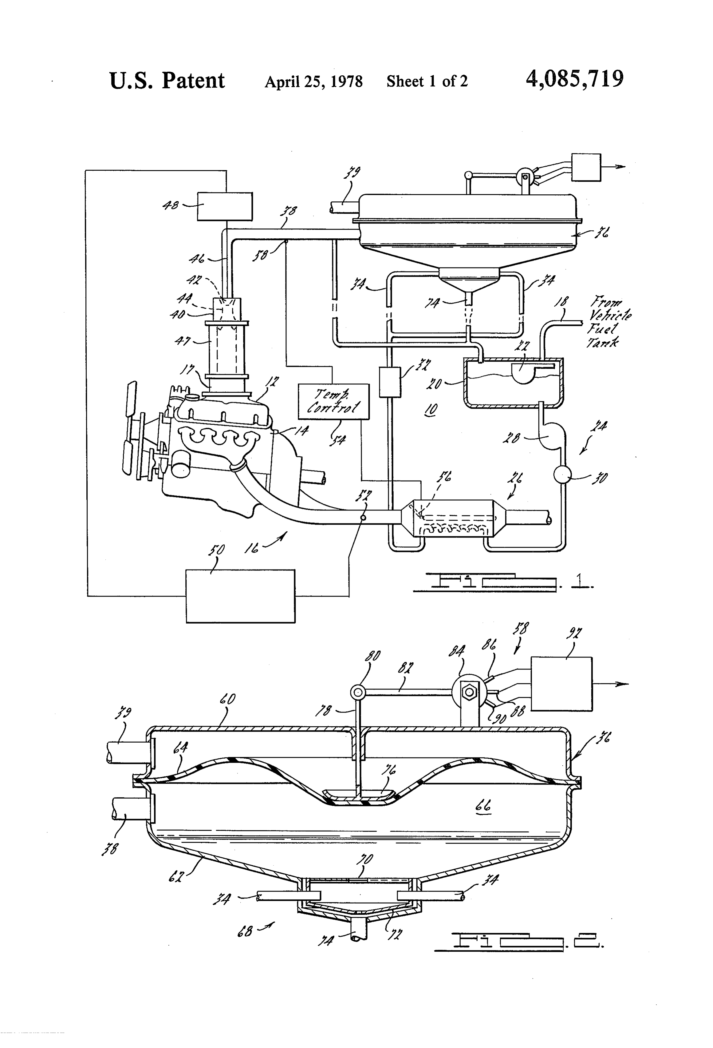
It is known that a liquid fuel may be advantageously reservoir to intermix with, and elevate the temperature converted to a vapor for mixture with air to establish a of, the vapor residing at the lowest point in the vapor combustible air/fuel mixture for delivery to an internal reservoir which vapor would be expected to be the combustion engine. However, prior art teachings with 50 lowest temperature vapor. In fabricating such a vapor respect to the delivery of a vaporized liquid fuel from a reservoir one would also attempt to remove the conden source of liquid fuel to an internal combustion engine sate of any vapor which had condensed within the have not adequately treated the technical question of vapor reservoir. Such condensate would be expected to how to maintain a supply of vaporized liquid fuel which accumulate, in liquid form, in the lowest portion of the supply is adequate for substantially all conditions of 55 vapor reservoir. It is therefore, a further and specific engine operation. It is therefore a specific object of the object of the present invention to provide means defin present invention to provide a vapor reservoir for re ing a thermal barrier, for receipt within the lowest por ceipt of a vaporized liquid fuel and for storage of the tion of the reservoir housing, to separate the relatively vaporized liquid fuel in vapor form for eventual deliv higher temperature inlet vapors from any relatively ery to an internal combustion engine. The prior art has lower temperature condensed liquid fuel. also not adequately treated the question of how to main SUMMARY OF THE PRESENT INVENTION tain a supply of vaporized liquid fuel under conditions which will allow maintenance of a substantially con The present invention provides a reservoir for receipt stant air/fuel ratio under substantially all conditions of and storage of a vaporized liquid fuel. The volume of engine operation. It is therefore a specific objective of 65 the vapor storage reservoir is arranged to be approxi the present invention to provide a vapor storage reser mately one-half of the total displacement of the combus voir for automatically maintaining a desired air/fuel tion chambers of the associated engine. The interior of ratio. the vapor reservoir is communicated to the intake sys 5 tem of an internal combustion engine for delivery FIG. 3 illustrates the electrical control circuit for thereto of a quantity of a vaporized liquid fuel. Vapor is maintaining an adequate supply of vaporized liquid fuel stored within the vapor reservoir at a pressure which in the vapor reservoir according to FIG. 1. equals or closely approximates the pressure existing DESCRIPTION OF THE PREFERRED immediately upstream from the intake system of the EMBODIMENT associated internal combustion engine. The vapor stor Referring now to the drawing wherein like numerals age reservoir is provided with a movable wall portion designate like structure which is referenced to the air pressure immediately thereof, FIG. 1 illustratesthroughout the various views upstream from the intake to the associated engine. The 10 ery and metering system 10 includingliquid a vaporized fuel deliv vapor storage reservoir is also provided with vapor sure regulator according to the present invention.pres the vapor The delivery control means which are responsive to the vaporized liquid fuel delivery and metering system 10 position of the movable wall portion to increase or arranged to provide a combustible mixture to the intakeis decrease the rate of vapor delivery to the vapor reser manifold 12 of an internal combustion engine 14. Inter voir. The vapor reservoir includes a housing member 15 nal combustion engine 14 is provided with combustion having a downwardly depending, cup-shaped portion by-product exhaust gas conduit means 16. Intake mani for the collection and drainage of any condensed va fold 12 is provided pors. Vapor delivery to the reservoir is arranged to be internal combustionwithengine throttle body 17. As illustrated, 14, intake manifold 12, through the dependent cup-shaped portion. A ther throttle body 17 and exhaust gas conduit means 16 are mally floating thermal barrier is arranged within the 20 substantially conventional. For purposes of illustration, dependent cup-shaped portion for separating inlet it will be considered that internal combustion engine 14 vapor from any condensed vapor. The thermally float is of the type adapted for installation and use in power ing portion includes swirl inducing fin members which ing an automotive vehicle, not shown.
are operative to promote mixing of the relatively higher System 10 is arranged to receive liquid fuel from a temperature inlet vapor with potentially lower tempera 25 conventional liquid fuel reservoir or tank, not shown, ture vapor residual within the vapor reservoir. through conduit 18. Conduit 18 communicates with The vapor delivery control means includes a liquid intermediate liquid fuel reservoir 20. The communica fuel metering means in the form of a valve adapted to tion between conduit 18 and intermediate reservoir 20 regulate and control, in a coarse fashion, the rate of may be controlled, for example, by a pivoted float valve delivery of the liquid fuel to the liquid vaporizer in 30 22 in the conventional manner. As will be appreciated, order to control the rate of delivery and accumulation liquid fuel could be pumped through conduit 18 by of vaporized liquid fuel within the vapor reservoir. An conventional pumping means such as the conventional electronic circuit is arranged to be responsive to means mechanical or electrical fuel pump normally used in indicative of the position of the movable wall member. automotive vehicles.
The electronic circuit is operative to generate a control 35 Liquid fuel contained in intermediate reservoir 20 signal for application to the coarse liquid fuel metering may be provided by coarse fuel delivery means 24 to means to controllably vary the rate of liquid fuel deliv primary heating means 26. Coarse fuel delivery means ery to the heating means. 24 may include for example, an electrical or mechanical Electrical means in the form of a potentiometer are liquid pump 28 and a liquid control valve 30. This struc arranged to generate an output signal which is indica ture is described in somewhat greater detail hereinbe low with reference to FIG. 3. An auxiliary heating tive of the position of the movable wall member. An means 32 is arranged in fluid serial flow relationship electronic circuit means is arranged to receive the po with respect tentiometer signal and to compare this signal with a fuel providedtofrom the primary heating means 26 so that intermediate reservoir 20 will flow reference voltage to determine the need for an increase or a decrease in the rate of delivery of liquid fuel to the 45 serially through the primary heating means 26 and heating or vaporizing means. Additionally, the circuit thence through auxiliary heating means 32. The auxil includes electrical means arranged to be responsive to iary heating means 32 are shown to be communicated via conduits 34 to a vapor storage reservoir and regula the position of the engine throttle valve member to tor selectively increase or decrease the rate of liquid fuel 0 voir3636according to the present invention. Vapor reser delivery to the vaporizing means in anticipation of reference to FIG. 2. in greater detail hereinbelow with is described change in the rate of consumption of the vaporized As illustrated in FIG. 1, the primary and auxiliary liquid fuel by the associated engine. These last men heating means 26, 32 are connected in serial fluid flow tioned means also are operative to prevent closed loop relationship. In order for efficient operation of the auxil stability in the control loop which includes the coarse 55 iary heating means 32, it should be designed for rela fuel delivery metering means, the liquid fuel vaporizer, tively low fuel flow consonant with operation of the the vapor reservoir and the electrical vapor delivery associated engine at idle. As such, however, the auxil control circuit which controls the coarse delivery me iary heating means could present a high impedance to tering means as a function of the position of the movable fluid flow and could impede engine operation under wall member. high fuel consumption conditions. It is therefore con BRIEF DESCRIPTION OF THE DRAWINGS templated that the primary and auxiliary heating means could be connected in parallel fluid flow. It is also con
FIG. 1 illustrates the vaporized liquid fuel delivery templated to provide a fluid by-pass valve downstream and metering system with which the present invention from to primary heating means 26 and upstream from is of utility. 65 the auxiliary heating means 32 to place the primary FIG. 2 illustrates the vapor reservoir according to the heating means 26 in direct fluid communication with the present invention in a partly section, partly diagram vapor reservoir 36 when the auxiliary heating means 32 matic view. are not required as a vapor supply source.
Page 6scan →
Vapor reservoir 36 is communicated by way of con collection section 68 and any condensed fuel which may duit 38 with carburetor means 40. As used herein "car be accumulated therein. Preferably, shield member 72 is buretor" means any device for mixing fuel with air to fabricated out of a low thermal inertia material such as establish a combustible air/fuel mixture. As illustrated a thin stainless steel or a suitable ceramic. Swirl fins 70 in FIG. 1, the vapor delivery nozzle 42 of vapor deliv promote intermixing of the higher temperature inlet ery conduit 38 is positioned within the low pressure vapor with any vapor residual within vapor zone 66 to zone formed by the metering venturi means 44 of the encourage relatively uniform temperature distribution carburetor means 40. A movable pintle 46 is situated within zone 66. In operation, any vaporized fuel which within the vapor delivery nozzle 42 and is controlled by would condense due to contact with a low temperature servomechanism means 48. Carburetor means 40 in 10. surface within the vapor reservoir 36, and particularly cludes mixing section 47 which intercommunicates the the less volatile fractions of gasoline, would be col metering venturi means 44 with the intake manifold 12. lected within section 68 and would flow through con Servomechanism 48 may be for example a conven densate return conduit 74 for return to the intermediate tional servomotor operated electrically or by electro tank. 20.
mechanical means. Servomechanism 48 receives an 15 A suitably sized vapor reservoir has been found to input command signal from servomechanism control approximately one-half the displacement of the associ means 50. As here illustrated, servomechanism control ated engine as such displacement is conventionally de means 50 are arranged to be responsive to an exhaust termined. Assuming that the force exerted by the posi gas sensor 52 which may be for example, a titania ex tion sensing means is 0.015 pounds and the accurate haust gas sensor according to U.S. Pat. No. 3,886,785. 20 maintenance of the air/fuel ratio will tolerate a maxi According to FIG. 1, fuel delivery and metering system mum pressure differential of 0.0001 pounds per square 10 is also provided with vapor temperature control inch (induced by the position sensing means) the area of means 54. Temperature control means 54 are arranged the movable wall member 64 must be at least 75 in.?. For to be responsive to the vapor temperature in vapor a circular movable wall member 64, a diameter of about delivery conduit 38 in order to control an exhaust gas 25 10 in. is adequate. Thus, the overall height of the vapor flow diverter valve 56. Valve 56 is operative to control reservoir need not exceed about 5 in. In arriving at the heating of the primary heater means 26. volume requirement, we have considered the extreme Referring now to FIG. 2, the vapor reservoir 36 and case to be an acceleration of the engine from about 600 its associated vapor pressure control means 58 accord RPM to about 3600 RPM in three seconds with the ing to the present invention are illustrated. Vapor reser 30 air-to-fuel ratio held at 15:1 and a volumetric efficiency voir 36 is comprised of a canister or housing having of 80%. We have also considered the availability of upper and lower housing sections 60, 62, respectively. vapor from the primary heater means 26 to be capable A movable wall member 64 is sealingly confined be of providing about one-half of the vaporized fuel re tween extending flanges of the upper and lower canister quired by the engine in undergoing the aforenoted ac housing sections 60, 62 to define a vapor tight vapor 35 celeration.
space or storage zone 66. Movable wall means 64 may The central portion of movable wall means 64 is be formed as a diaphragm member and may be fabri connected to plate member 76. Plate member 76 is con cated from any suitable, flexible, high temperature and nected to movable position sensing rod 78. Position vapor resistant material. Movable wall means 64 may sensing rod 78 is pivotally connected at pivot 80 to lever be, for example, in the case of vaporized liquid gasoline, arm 82 of rheostat member 84. Rheostat member or a polytetrafluoroethylene (PTFE) material. Other ma potentiometer 84 is provided with three electrical ter terials are known and can be used. PTFE material has a minals 86, 88 and 90 which communicate with the vapor maximum operating temperature in the contemplated volume control means 92.
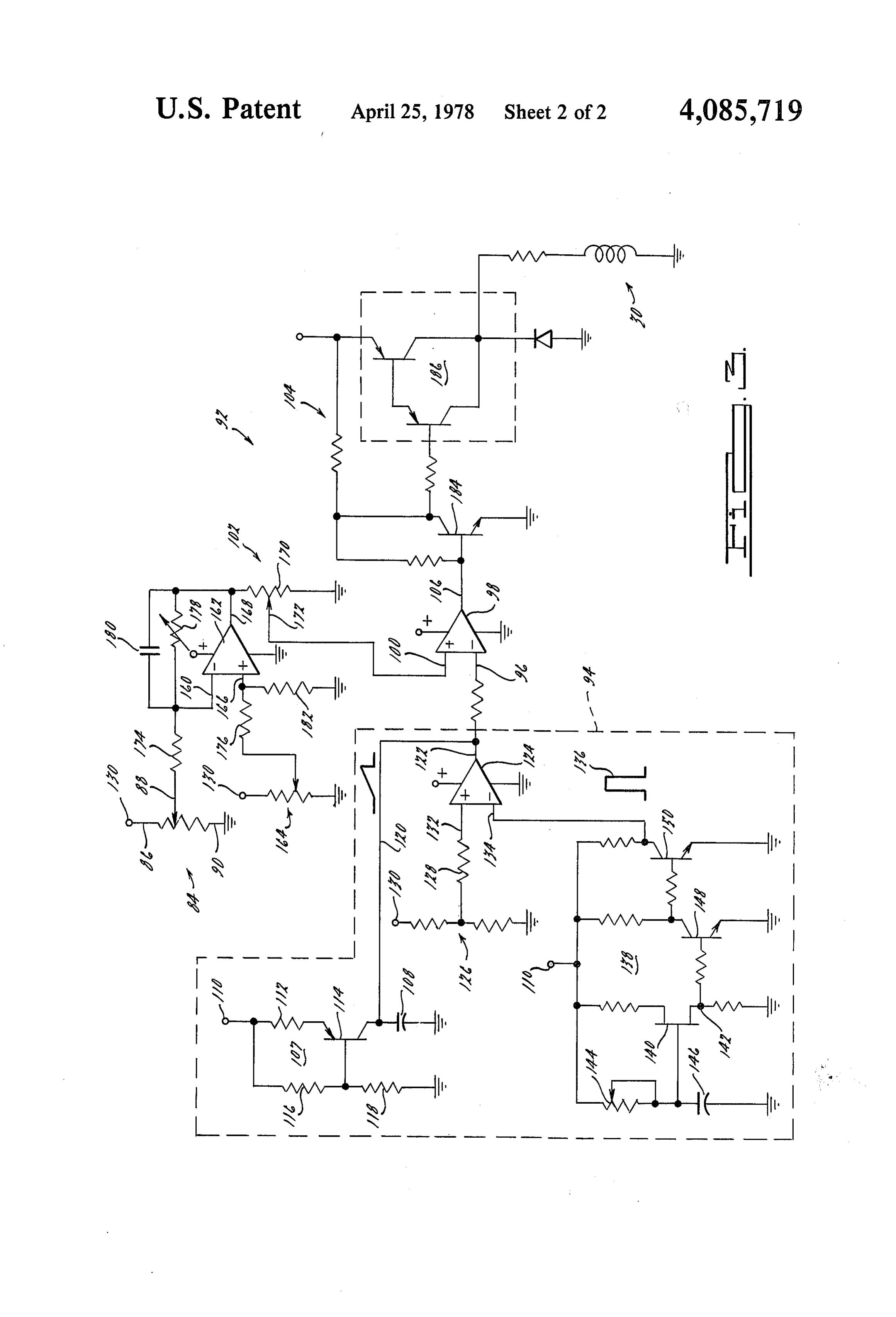
environment of about 600 F while commercially avail Vapor region 66 communicates with the engine 14 able gasoline may be expected to be completely vapor 45 through vapor conduit 38. Reference conduit 39 com ized at temperatures not exceeding 450 F. A suitable municates the upper housing section 60 and particularly thickness for such a diaphragm member has been found the nonvapor surface of movable wall means 64 with to be 2 mils. Smaller thicknesses are also suitable, pro the source of air being utilized by internal combustion vided that manufacturing induced defects such as perfo engine 14. In those instances where the air being in rations are avoided. 50 gested by engine 14 passes through an air cleaner, con Lower canister housing section 62 is provided with a ; : duit 39 would preferably communicate with the interior downwardly extending vapor inlet and condensate col of the air cleaner. In those instances where atmospheric lection section 68. Vapor delivery conduits 34 are ar air is provided directly to internal combustion engine ranged to direct a vapor stream into the interior of 14, reference conduit 39 would communicate directly to section 68 where the vapor may communicate through 55 the atmosphere. Reference conduit 39 thus provides the swirl fins 70 with the vapor storage zone 66. A shield nonvapor side of movable wall portion 64 with a pres member 72 is received within section 68 and is attached sure reference which is substantially identically equal to to and supported by vapor inlet tubes 34. Condensate the pressure of the air being provided to, and immedi collection section 68 is provided with a generally down ately upstream from, carburetor means 40. wardly extending generally conical and plate member Referring now to FIG. 3, the vapor volume control having condensate collection conduit 74 affixed thereto means 92 of FIG. 2 is illustrated as an electronic circuit. at its lowest point. Shield member 72 is arranged to be Vapor volume control means 92 is adapted to control spaced away from the walls of condensate collection valve 30 of coarse liquid fuel delivery means 24 in re section 68 and to be thermally floating with respect to sponse to the quantity of vapor within vapor region 66 the lower housing member 62 and the condensate col 65 as indicated by potentiometer 84. In the presently pre lection section 68. Shield member 72 is arranged to ferred embodiment of the vaporized liquid fuel system, provide a barrier between the relatively high tempera liquid fuel delivery means includes metering valve 30 ture inlet vapor and the lower temperature condensate which is a commercially available electrically con 7 trolled injection valve used, for example, in electronic transistorized gate circuit 124 to approach ground fuel injection systems. Such valves are designed and value. This will impose a substantially ground voltage intended to deliver a metered quantity of liquid fuel to on conductor 120 to thereby discharge capacitor 108. the intake manifold of an internal combustion engine in Removal of the pulse from input terminal 134 will allow proximity to an intake valve. It will be appreciated that 5 capacitor 108 to recharge. Thus, a saw tooth voltage a fuel pump means 28 could be similarly controlled to signal going from a near ground or zero value to a coarsely meter liquid fuel delivery to the heating means. maximum or full value voltage will be applied to termi Vapor volume control circuit 92 includes a first circuit nal 96 of comparator 98. The pulse width of the output portion, contained within dashed line 94, for generating signal generated at output terminal 106 by comparator a saw tooth wave form for application to one input 10 98 will then be a function of the voltage appearing on terminal 96 of a comparator 98. The other input termi input terminal 100.
nal 100 of comparator 98 is arranged to receive a vari The oscillator circuit 138 includes unijunction transis able voltage signal from control circuitry 102. This tor 140 and associated circuitry operative to generate a variable level voltage signal is generated in response to pulse train at circuit junction 142. The associated cir potentiometer 84. Valve control circuitry 104 is respon 15 cuitry includes variable resistance 144 and capacitor 146 sive to the output signal from comparator 98 appearing arranged in an RC network and operative to periodi at output terminal 106 to selectively energize the liquid cally charge and discharge the capacitor 146 to cause fuel delivery coarse metering valve 30. breakdown of the unijunction transistor 140. The pulses Saw tooth generator 94 includes a ramp generator appearing at circuit junction 142 may be shaped by portion 107 which is operative to generate a linearly 20 additional circuitry associated with transistors 148, 150 increasing voltage across capacitor 108. Capacitor 108 to establish the pulse train of pulses 136 having a gener is charged by current flow from the terminal 110 ally uniform pulse width with rapid rise and fall. Resis through resistor 112 and transistor 114. Transistor 114 is tance 144 is here shown to be variable in order to vary held in an "on' or conductive condition by the voltage the frequency of the resulting pulse train. We have divider comprised of a pair of resistances 116, 118, 25 found that a pulse frequency of 50 Hz and a pulse width which may be, for example, of the same resistance of 0.1 usec. gives good results.
value. Resistances 116, 118 are operative to apply a The potentiometer 84 is connected by its terminals 86, reduced voltage such is approximately one-half of the 90 between a voltage terminal, such as terminal 130, and input voltage to the base terminal of transistor 114. ground. The slider 88 of potentiometer 84 is coupled to Transistor 114 will be conductive and will charge ca 30 the movable wall member 64 of vapor reservoir 36 as pacitor 108 whenever the voltage on the base terminal described hereinabove with reference to FIG. 2. The exceeds the voltage on the collector terminal and is less voltage developed by potentiometer 84 at slider 88 is than the voltage on the emitter terminal. The rate of therefore a function of the position of the position of the change of capacitor 108 can be controlled by the magni movable wall member 64 and hence of the quantity of tude of resistance 112. 35 vapor within the vapor region 66. This voltage is ap Capacitor 108 intercommunicates the collector of plied to one input terminal 160 of comparator 162 to be transistor 114 to ground. The other or nonground side compared with a reference voltage applied at input of capacitor 108 is communicated by conductor 120 to terminal 166. The reference voltage is developed by output terminal 122 of transistorized gate circuit 124. potentiometer 164. Comparator 162 is arranged to pro One input terminal of transistorized gate circuit 124 is 40 vide an output signal at output terminal 168 which sig provided with a constant voltage signal derived from a nal represents the difference between the applied input conventional voltage divider 126 through resistance signals. The output signal appearing at output terminal 128. Voltage divider 126 is connected electrically be 168 is applied through potentiometer 170 to the input tween terminal 130 and the ground and is operative to terminal 100 of comparator 98.
provide a constant voltage signal at input terminal 132. 45 The input terminals 160, 166 of comparator 162 are For purposes of this circuit description, voltage termi provided with input resistances 174, 176 respectively. In nal 110 may be considered to represent a first level of addition, variable feedback resistance 178 and capacitor voltage and voltage terminal 130 may be considered to 180 are arranged electrically in parallel interconnecting represent a second level of voltage with all similarly input terminal 160 with output terminal 168. The ratio designated terminals being in electrical communication 50 of the resistance of feedback resistance 178 compared with the same voltage source. Transistor 114 is ar with the resistance of input resistance 174 will establish ranged to act as a constant current source in charging the gain of the comparator and the gain so established capacitor 108. The voltage across capacitor 108 will can be expected to be stable in extended use. Capacitor increase substantially linearly until a value is reached 180 is selected to prevent relatively high frequency which would reverse bias the base-collector junction of 55 variations in the voltage appearing at output terminal transistor 108 causing the transistor to switch off. 168. This is desirable to prevent a relatively high fre Input terminal 134 of transistorized gate circuit 124 quency instability in the closed loop which includes the receives a periodically repeated voltage pulse signal, "mechanical' elements of the primary heater means 26 such as at 136, which is generated by oscillator circuit and the vapor reservoir 36. For good d.c. stability, the 138. Oscillator circuit 138 is electrically energized from values of resistance of the input resistances 174, 176 are a voltage terminal 110. Oscillator circuit 138 is opera selected to be substantially equal. The value of the tive to generate a voltage pulse which goes from sub grounding resistance 182 is also selected to be approxi stantially the ground level to substantially the value of mately equal to the value of the feedback resistance 178 the source voltage and has a very narrow pulse width. for good d.c. stability.
The occurrence at input terminal 134 of a pulse having 65 With potentiometer 84 disconnected, potentiometer a voltage value which is in excess of the voltage value 164 is adjusted to make the voltage at output terminal of the generally constantly applied voltage appearing at 168 sufficiently high to just provide maximum fuel de terminal 132 will be operative to cause the output of livery to the primary heater means 26. Potentiometer 84 8 is then connected and adjusted, with the movable wall substantially conventional 10 portion 64 in a down, or vapor depleted condition, so conduit 38 is provided withmetering venturi 44. Vapor that the voltage at output terminal 168 is as previously which is situated within the metering venturinozzle
44 of the set. Feedback resistance 178 is then adjusted to give a carburetor means 40. Vapor conduit 38 is arranged to zero output voltage at output terminal 168, correspond place the orifice of vapor delivery nozzle 42 within the ing to the vapor reservoir being filled, by holding the low vapor reservoir movable wall portion in an up or 44. Inpressure region established by the metering venturi this embodiment, metering venturi 44 is arranged "filled' condition. As illustrated in FIG. 2, a depleted vapor supply in reservoir 36 will cause the voltage gent to define an air flow passage which is rapidly conver appearing at input terminal 160 to decrease. The voltage 10 on its upstream side and gradually divergent on its downstream side. The terms "upstream' and "down appearing at output terminal 168 is arranged to increase stream' as the voltage at input terminal 160 decreases from the relate to the direction of intake air flow. reference level established by potentiometer 164. As a coarse measure of air/fuel ratio control, the ratio Potentiometer 170 is connected between output ter of the area of the venturi 44 in the plane of the orifice of minal 168 and ground. The slider 172 of potentiometer 15 vapor delivery nozzle 42 when compared to the area of 170 is connected to the input terminal 100 of compara the orifice of the vapor delivery nozzle 42 should be tor 98. The slider 172 may also be connected to the slightly less than that which would produce the desired apparatus controlling the position of the throttle valve air/fuel ratio. We have determined that the air/fuel within throttle valve body 17. For example, a closed ratio is approximately equal to seven tenths (0.7) of the throttle condition would cause the slider to reduce the 20 ratio of the air delivery area compared to fuel delivery level of the voltage signal applied to input terminal 100. area. This relationship is an approximation and is based This arrangement will operate to vary the effective gain on air at 70 F. and commercially available gasoline, as of comparator 162 in response to actual operation of the fuel, vaporized at 400 F. By modulating the actual internal combustion engine 14 to assist in filling the area of fuel delivery, through use of a movable pintle vapor reservoir when the throttle valve of the engine is 25 and needle valve, for example, the actual air/fuel ratio opened and to assist in preventing excess vapor forma may be modulated and a desired air/fuel ratio may be tion when the throttle valve is moved toward a closed precisely attained. In view of the fact that fuel vapor is position. Potentiometer 170 will also assist in preventing provided to the moving air stream with substantially the relatively low frequency instability in the loop which same pressure differential through the orifice of vapor includes primary heater means 26 and vapor reservoir 30 delivery nozzle 42 as is experienced by the air stream in flowing from the upstream side of metering venturi 44
Comparator 98 is arranged to generate an output to the plane of the orifice of nozzle 42 and is delivered voltage signal at output terminal 106 whenever the to the low pressure region defined by the air stream voltage appearing on input terminal 96 is below the moving through metering venturi 44, the mass of vapor level of voltage established at the input terminal 100. 35 ized liquid fuel can be precisely controlled to match the Thus, with a saw tooth input signal at input terminal 96, mass of air being consumed by the associated engine to a pulse train of rectangular pulses will be generated at maintain a preselected and desired air/fuel ratio for all output terminal 106 with a frequency equal to the fre mass ratios of air flow.
quency of the saw tooth wave train and a pulse width The precise area of the orifice of fuel delivery nozzle determined by the portion of any particular saw tooth 42 may be varied by the movement of pintle 46 in order pulse which is below the threshold voltage. The output to vary the area of the fuel delivery nozzle and hence signal will be applied to output transistor 184 which will the quantity of vaporized liquid fuel being provided to invert the signal to apply an input to the power ampli the engine through vapor delivery conduit 48. A throt fier circuitry 186 to control energization of the coarse tle valve situated within throttle body 17 may be opera fuel metering valve 30. Thus, when vapor reservoir 36 45 is full, the threshold signal will be substantially zero and tive to vary the rate of delivery of the combustible the output signal at terminal 106 will be substantially from themixture air/fuel to the intake manifold of engine 14 carburetor means 40. The throttle valve may constant at the zero level. This will turn output transis tor 184 “off” thereby applying a high voltage signal to be operated in the conventional manner. Preferably, the orifice of vapor delivery nozzle 42 will be placed within power amplifier 186 causing power amplifier 186 to be 50 the region "off'. This will result in closing coarse fuel metering the zone ofdefined maximum by metering venturi 44 at or within depression (minimum pressure) in valve 30 and terminating fuel delivery to the primary order to provide the greatest pressure differential across heating means 26. As the vapor is depleted from vapor the orifice. However, accurate reservoir 36, the threshold signal will rise causing the low pressure zone is not critical placement since the within the vapor pres output signal to appear as a train of pulses at the saw 55 sure is referenced to substantially the same pressure as tooth frequency. The pulse portion of the output signal exists upstream from the metering venturi 44 and the pulse train will switch output transistor 184 "on' and size of the minimum pressure zone defined in the direc will cause the power amplifier to be "on' to energize tion of flow is variable.
coarse fuel metering valve 30. With valve 30 on or We claim:
open, additional quantities of liquid fuel will be allowed 1. A reservoir for storage of a vaporized fuel which is to flow to the primary heater means 26 for vaporization liquid at standard temperature and pressure comprising thereby. For very low volumes of vapor in vapor reser in combination:
voir 36, the threshold signal will be high and the pulse housing means;
width will increase thereby increasing the "on' time of movable wall means received within said housing power amplifier 186 and the open time of coarse fuel 65 means cooperative with said housing means to metering valve 30.
Referring now to FIGS. 1, 2 and 3, it can be seen that define a variable volume vapor storage zone; carburetor means 40 is provided with means defining a inlet fluid conduit means communicating in fluid tight relation with said vapor storage zone;
Page 9scan →
outlet fluid conduit means communicating in fluid means operative to communicate said vapor stor tight relation with said vapor storage zone; age zone with a vaporized liquid fuel utilization said inlet fluid conduit means operative to communi means;
cate said vapor storage zone with a source of va reference means communicating the nonvapor side of porized liquid fuel and said outlet fluid conduit 5 said movable wall means with a preselected refer means operative to communicate said vapor stor ence pressure whereby the vapor pressure may be age zone with a vaporized liquid fuel utilization arranged to have a predetermined relationship with means; respect to the reference pressure; reference means communicating the nonvapor side of said movable wall means comprising a diaphragm said movable wall means with a preselected refer- 10 member formed of a thin flexible material which is ence pressure whereby the vapor pressure may be selected to be compatible with the vaporized liquid arranged to have a predetermined relationship with fuel;
respect to the reference pressure; electrical means responsive to the position of said cup-shaped condensate collection means dependent diaphragm member operative to generate an elec from said housing means arranged for fluid com- 15 trical signal indicative of the quantity of vapor munication with a reservoir of the liquid fuel; within said vapor storage zone; and said inlet fluid conduit means being attached to said electronic means responsive to said electrical signal condensate collection means whereby higher tem operative to generate an electrical signal for appli perature inlet vapor from said inlet fluid conduit cation to liquid fuel delivery means for controlling means may elevate the temperature of vapor within 20 the delivery of vapor to the vapor storage zone. the lower portions of the vapor storage zone; and thermally floating separator means received within said4. electronic
The vapor reservoir according to claim 3 wherein means comprise:
and spaced apart from said condensate collection oscillator means for generating a periodically repeat means and supported by said inlet fluid conduit ing voltage signal waveform; means operative to provide a thermal barrier be- 25 variable threshold means responsive to said electrical tween vapor flowing through said inlet fluid con signal operative to generate a variable voltage duit means and condensed vapor. threshold signal;
2. The vapor reservoir according to claim 1 wherein comparison means for comparing said waveform and said thermal separator means include a plurality offin said threshold signal operative to generate an out members in proximity to the outlet orifices of said inlet 30 put signal for a selected relationship of said thresh fluid conduit means operative to promote intermixing of old signal and waveform; and inlet vapor with vapor residual within said vapor stor output amplifier means responsive to said output age space. signal operative to generate a liquid fuel delivery 3. A reservoir for storage of a vaporized fuel which is control signal whereby the delivery of liquid fuel liquid at standard temperature and pressure comprising 35 to a vaporizer for charging said reservoir with a in combination:
housing means; vapor may be controllably regulated. movable wall means received within said housing ing:5. The vapor reservoir according to claim 4 includ means cooperative with said housing means to define a variable volume vapor storage zone; 40 electrical means within said threshold means and inlet fluid conduit means communicating in fluid tight operatively associable with an engine throttle, op relation with said vapor storage zone; erative to vary the threshold signal as a function of outlet fluid conduit means communicating in fluid throttle position whereby the delivery of liquid fuel tight relation with said vapor storage zone; for vaporization may be increased or decreased in said inlet fluid conduit means operative to communi- 45 accordance with anticipated engine requiremnts as cate said vapor storage zone with a source of va suggested by throttle position changes. porized liquid fuel and said outlet fluid conduit
Provenance
- Collection
- Patents citing this work
- Pages
- 9
- Method
- pdftotext (the PDF's own text layer) + pdftoppm 300dpi page scans
- Patent office record
- patents.google.com →
- Source
- Google Patents citing-documents table
- Assignee
- Ford Motor Company
- Published
- 1978-04-25
- Transcribed from
- patentimages.storage.googleapis.com →