

patent · US2918117A
Heavy fuel burner with combustion gas recirculating means
22 December 1959
Text
Drawings
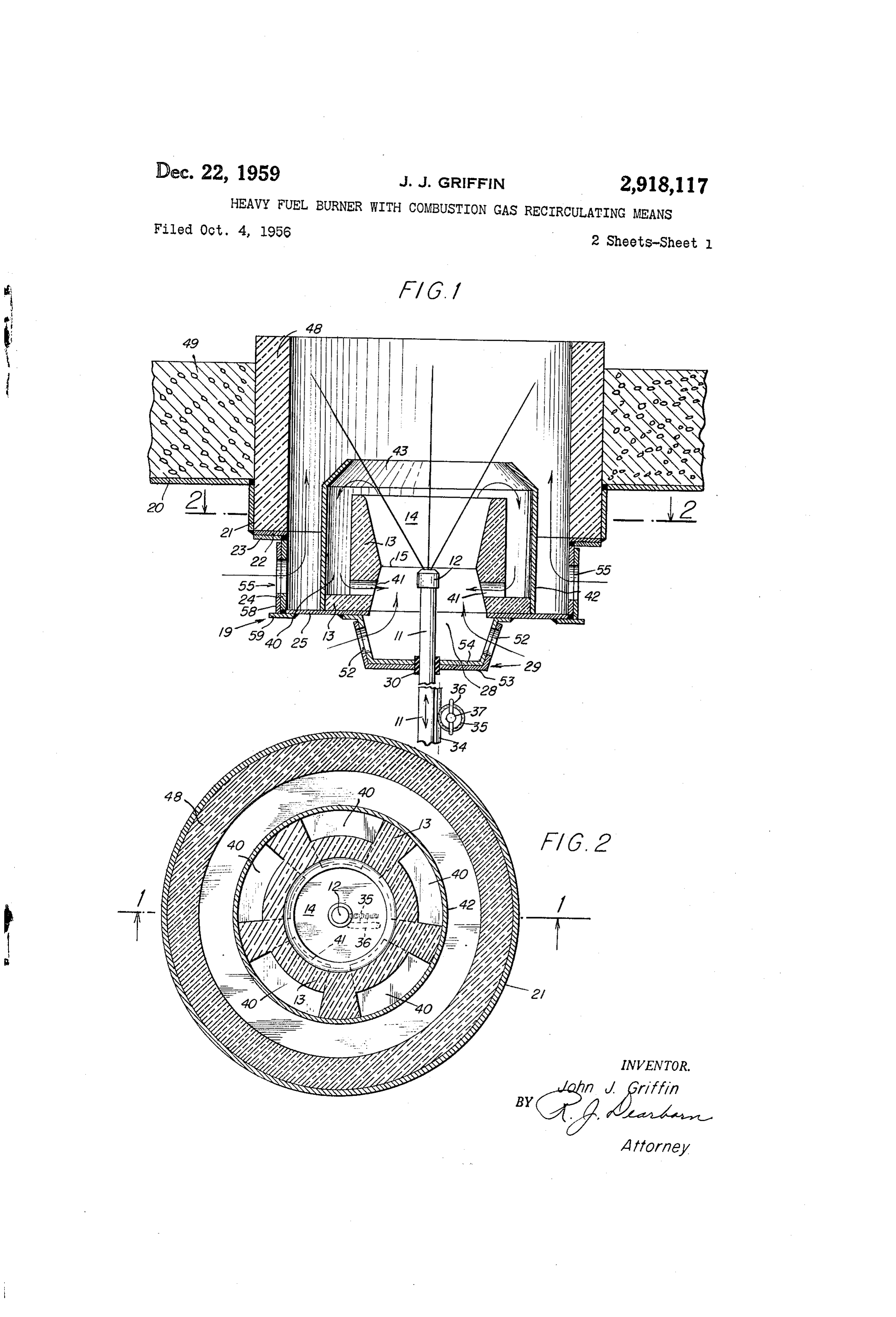
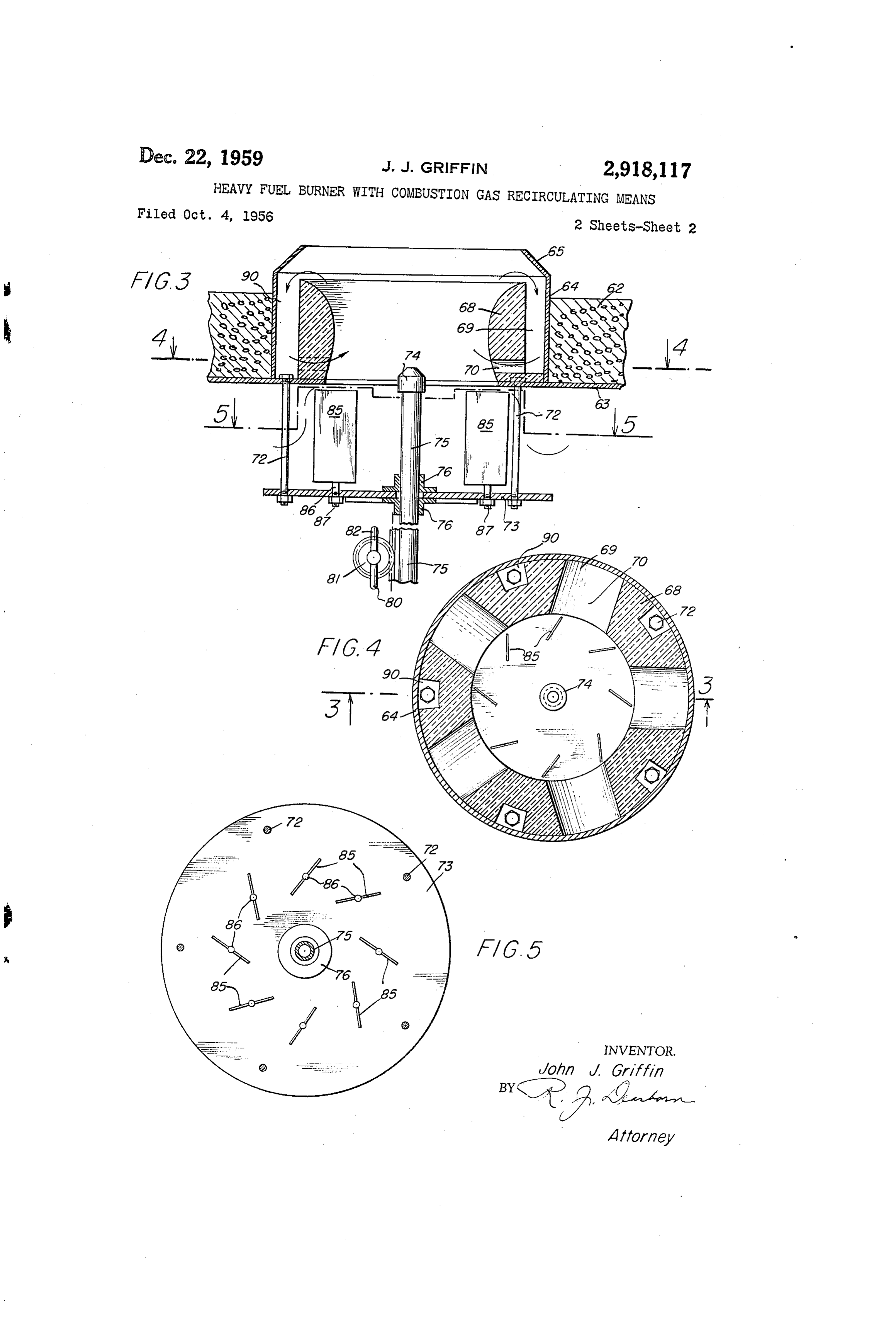
Fig. 2 is a cross-section plan view taken along the
Page 1drawing sheetscan →
Page 2drawing sheetscan →
Page 3scan →
United States Patent Office Patented Dec. 22, 1959 turning some of said combustion products into said venturi means near the throat thereof. Also the said 2,918,117 venturi means has a passage near the throat thereof for HEAVY FUEL BURNER WITH COMBUSTON (GAS recirculating the returned portion of said combustion
Some embodiments of the invention are described be
John J. Griffin, Huntington, N.Y., assigaor to Petro low in more detail, as an illustration thereof. These Chem Process Company, incorporated, New York, embodiments are hereafter described and illustrated in N.Y., a corporation of Delaware the drawings, in which:
Application October 4, 1956, Serial No. 613,867 0. Fig. 1 is a vertical cross-section view showing a double block type burner mounted in the floor of a furnace
Claim. (C. 158-1) or the like, taken along the lines - of Fig. 2 look ing in the direction of the arrows;
Fig. 2 is a cross-section plan view taken along the
This invention is concerned with liquid fuel burners in 5 lines 2-2 of Fig. 1;
general. More specifically the invention deals with a Fig. 3 is a vertical cross-sectional view of a single vertical or upshot type of burner, to be used in furnaces block type burner;
generally and more particularly in commercial types Fig. 4 is a horizontal cross-sectional view taken along having large heating capacity. Furthermore, the inven the line 4-4 of Fig. 3, looking in the direction of the tion is especially concerned with an upshot burner for 20 arrows; and handling heavy fuels. Fig. 5 is a plan view partly in cross-section, taken In referring to liquid fuels, it is intended to include along the lines 5-5 on Fig. 3.
both fuels that are principally supplied as liquids and Referring to both Figs. 1 and 2 of the drawings but then are atomized in the burner, as well as fuels that 25 primarily with reference to Fig. 1, it will be observed are basically solid in their original form, but which have that the burner consists of a fuel supply pipe which been ground so as to be in powder form or at least stands vertically and is centrally located along the verti in comparatively finely divided particles. The latter solid cal axis of the entire burner. At the upper extremity type of fuel being one which may be ejected from a or tip of pipe there is a nozzle 12 that may take nozzle in the form of a suspension, such that it acts as any desired form, partly depending upon the type of fuel a fluid. 30 to be employed. For the purposes of illustration, it will It has been found that where heavy fuels are em be assumed that the pipe 1 and the nozzle i2 together ployed, difficulty is encountered in obtaining complete make up a steam-atomizing type of burner nozzle. It combustion thereof. This is particularly true where the is pointed out that the burner itself will operate equally burner is employed as a so-called upshot burner. The 35 as well where the atomizer nozzle 12 is of a mechanical problem is especially noticeable in making use of high type.
viscosity high gravity refinery pitches. Such fuels which Surrounding the entire nozzle, made up of nozzle or include relatively large percentages of pitch, produce a fuel pipe 1 and nozzle tip 12, there is a cylindrical block situation such that even after the burner is operating of refractory material 13 which has a venturi passage under full heat conditions, there is encountered a dripping 40 14 centrally located therein. It will be appreciated that of unburned fuel which falls back into the primary air this cylindrical block 13 may be constructed of other supply structure of the burner. This creates a clogging types of heat resistant material as well as a refractory, in addition to the messy accumulation of pitchy oils. e.g., it may be made of stainless steel, among others. Thus, the operation is relatively inefficient in addition Therefore, it is not intended to preclude other mate to providing the operational difficulties already mentioned. 45 rials even though the block 13 is referred to as a re It is pointed out that similar difficulties are to be ex fractory as a matter of convenience in the descriptions. pected where an upshot burner employs other types of The relative location of this venturi passage 14 and the fuels which have heavy constituents, such as some finely refractory cylinder 13, with respect to the fuel pipe 11 divided types e.g. powdered coal and the like. and its nozzle 12, is such that they are coaxial. The In view of this situation, it is an object of this in 50 nozzle 12 is centrally located within venturi passage 14, vention to provide a superior type of upshot burner for slightly below a minimum diameter, or throat section burning heavy types of fuels. 15 of the venturi passage 14. The refractory block 13 Another object of this invention is to provide in is supported by a housing structure 59 which may be proved structure for an upshot type of burner such that attached in any convenient manner to an outer layer or a portion of the combustion products as they leave the 55 skin 20 of the furnace. In the illustrated arrangement, stream being ejected from the burner nozzle, are circu it will be observed that there is welded to the furnace lated back into the stream of the combustion supporting skin 20 a wide band or ring 21 of the same structural ma gases that are being introduced around the burner terial as furnace skin 20. Welded to the lower edge nozzle. of ring 21, there is an annular disc or supporting plate Another object of this invention is to provide an upshot 60 22. The housing 19 proper is attached to the disc or burner of a superior construction such that no difficulty supporting plate 22 by any convenient means Such as by is encountered in burning the heaviest grades of fuels welding for example. The housing 19 includes an annu therewith, and a complete and entire combustion of lar disc or ring 23 which lies just beneath and in contact such fuels is obtained. with, the disc 22; a band or short cylindrical side wall Briefly, this invention includes a heavy liquid fuel 65 member 24, which is welded to ring or disc 23; and a burner that is comprised of a nozzle means for atomiz floor plate or disc 25, which is welded to the lower edge ing a liquid fuel. The burner also being comprised of of the wall member 24.
venturi means surrounding said nozzle means and having Centrally located in the floor plate 25 of the housing an opening at one end thereof for admitting combustion 19 there is an opening or hole 28 which lies directly sustaining gas, and an opening at the other end thereof 70 under, in alignment with the lower end of the venturi for ejecting combustion products. Further, the burner otherwise14,attached passage so as to coincide therewith. Welded or to the floor 25 around the edges of comprises means surrounding said venturi means for re 4 the hole 28, there is a nozzle supporting structure 29 this stream of finely divided particles of fuel may be which has a bearing sleeve 30 carried thereby. Bearing created in any feasible manner such as by use of a steam 30 in its turn, slidably carries the nozzle pipe 11. atomizing nozzle, or by use of a so-called mechanical type It will be observed that nozzle tip 12 is vertically ad of atomizing nozzle. It will be appreciated that the justable in its position, or location, within the venturi Inechanical type of spray nozzle for liquid fuels, is one passage 14 by means of any convenient mechanical ar where a relatively small sized orifice is employed with a rangement Such as that illustrated. This structure in high pressure supply of the liquid fuel introduced thereto. cludes a rack 34 that is securely attached to one side of In this way the ejected stream of the liquid fuel is ejected fuel pipe 11 and lies longitudinally there along, and a in a forceable manner, but at the same time is broken up pinion 35 which engages with the rack 34 for causing O into finely divided particles, i.e., is atomized. a vertical movement or positioning, of the rack by a The atomized fuel is ignited initially by a conventional vertical sliding up and down of the attached pipe 11 gas lighter (not shown) or by inserting a hand torch upon rotation of the pinion 35. There is also a handle through the primary air openings 52 into the venturi pas 36 attached to a shaft 37 which carries the pinion 35 sage 14.
Securely attached thereto for rotation therewith. Thus, 5 Such jet stream of atomized fuel induces a flow of in a mechanical adjustment may readily be made for regu take air that is drawn upward through the venturi pas lating the flame of the burner if desired, by changing the Sage 4, after it has entered via primary air intake pas relative position of nozzle tip 12 within the length of the sages 52. A combustible mixture of fuel and air is thus venturi passage 14. formed within the venturi passage 14, and the flame or It will be observed that the refractory material block 20 dinarily maintains itself beginning a relatively short dis 13 is cylindrical in general outline, but that there are a tance away from the ejection end of nozzle tip 12. In plurality of vertically extending notches or passages 40 other words the products of combustion become and re that are circumferentially spaced from each other around main nascent for some distance while still within the the outside surface of the block 13. At the bottom of venturi passage 14 and after leaving the same. Then, each of the passages 40 there is a short radial opening 41 25 as these products of combustion continue upward and which passes through the refractory block 13 so as to out of the burner proper toward the muffle tube 48, and connect each passage 40 with the venturi passage 14 some the inside of the given furnace or wherever the burner what below the minimum diameter or throat section 15. is employed; they pass the top edges of cowl 42, so that Surrounding the refractory block 13, there is a relatively the portion of this stream of nascent and other combus thin cylindrical cowl 42. This cowl 42 sits closely against 30 tion products at its outer edges become diverted by the the maximum diameter portion of the refractory block 13 frusto-conical ring 43 of the cowl back into the recircula and forms the outer wall or boundary of the vertical tion passages 40 around the edges of the refractory block portion 40 of recirculation passages 40, 41. At the top 13 (within which venturi passage 14 is formed). Such edges of the cylindrical body portion of cowl 42 there recirculation of hot combustion products takes place by is a frusto-conical ring 43 which is integrally connected 35 reason of standard venturi action wherein a lower pres to the top edges of the cowl 42, and which extends in Sure is created near the throat section 15 of venturi pas ward to an extent such that the top edge of the ring 43 sage 14. Thus, the frusto-conical ring 43 of the cowl lies directly over the inside, or minimum radius curved acts Substantially as a suction manifold and the diverted Surface of the recirculation passages 40. Cowl 42 includ 40 portion of the nascent combustion products will be drawn ing its inward sloping edge 43, is made of a high tem down through the passages 40 and via radial openings 41 perature resistant material, e.g. alloy steel, or the like. into the incoming air stream which constitutes the pri Situated coaxially with, and surrounding the upper por mary Source and Surrounds nozzle pipe 11 and the nozzle tion of the burner structure so far described, there is a tip 12. In this manner these hot nascent combustion muffle tube 48 which may be formed of a refractory 45 products cause the primary source of the incoming air material and which extends upward through the full depth Stream to be highly heated prior to reaching the lower of a refractory floor-layer 49 of the furnace. edges, or beginning, of the burner flame. In this manner It will be observed that there are primary air openings the incoming mixture is heated above the vaporization or ports 52 situated in the mounting structure 29 that temperature So as to cause complete revaporization of Supports the fuel nozzle pipe 11. These primary air in 50 any heavy particles of fuel which are forming and tend lets may be adjustable if desired as by means of the ing or beginning to fall out of the fuel stream. Conse illustrated structure wherein there is an outer layer 53 quently, there is complete vaporization of the entire fuel and an inner layer 54 which are relatively movable in employed even though the burner is operated as an up rotation about the bearing 30 so that the size of the shot burner in a directly vertical position. ports or openings 52 may be regulated by setting the 55 In the embodiment of Fig. 1, the complete combustion outer layer 53 more or less in correspondence with the of the fuel employs some secondary air intake through inner layer 54 in respect to the holes through each. In ports 55, as indicated above. This amounts to about like manner there is a secondary, or outer air inlet struc twenty to forty percent of the total air intake. ture that includes a plurality of openings or ports 55 For different grades of heavy fuel the nozzle pipe 11 which allow the secondary air to pass there-through into 60 and its ejection tip 2 may be adjusted but normally, as the space Surrounding cowl 42 and inside of the muffle already pointed out, the tip is always slightly below the tube 48. Here again the effective size of the openings venturi throat.
55 for the passage of secondary air may be made adjust This construction and burner arragement uses mechan able by providing for relative sliding movement between ical means to adjust the burner nozzle, not particularly the inner side wall member 24 and an outer layer 58 that 65 to change the flame shape, but to vary the quantity of may be attached in any convenient manner such as by flue gas recirculated. The heavier fuels will require more slideably resting on a flange 59 which is attached to recirculated products to insure operation without dripping. the floor plate 25 by welding. It should be noted that the simple mechanical adjust Operation ment of the burner nozzle in this invention can be safely 70 made while the burner is in operation thereby to obtain
The operation of the burner may best be described the optimum conditions for any given fuel. with reference to Fig. 1 where it will be observed that the However, in an emergency if it is necessary to use a fuel is forceably ejected in an atomized spray vertically light grade of fuel, this may be provided for by raising upward from the nozzle tip 12, as indicated in the draw the nozzle pipe 11 until the ejection tip 12 is at or near ing by the diverging lines shown. As indicated above, 75 the top of the venturi passage and thus eliminate the re 5 circulation effect which would be unnecessary under such employs narrow grooves 90 cut out of the block 68 at conditions. the peripherial location for each of the supporting bolts A modified form of burner in accordance with the in 72. This allows easy access to the bolts for mounting vention is illustrated in Figs. 3, 4, and 5. This form of and dismounting the burner structure while also reduc burner is a so called “single block” type of burner, which ing the quantity of heat resistant material used in the means that the entire burner structure is contained in a block 68.
single unit housing, and all of the combustion supporting It is pointed out that in this modification, the entire air is drawn in at a single air inlet for the burner. amount of combustion supporting air needed is drawn Basically the elements of the burner are the same as the in at the burner, without any provision for introduction elements employed in the inner portion of the above de O of secondary air. However, in general, the operation of scribed modification. Consequently, the details of such the burner with respect to the recirculation of nascent elements and their functional inter-relation, will not be products of combustion, is substantially as described described again in great detail. above in connection with the other modification. Referring to Figs. 3, 4, and 5, it will be noted that While particular embodiments of the invention have there is illustrated a portion of a furnace floor 62 which 5 been described above in compliance with the applicable has the usual thick layer of refractory material Supported statutes, this is not to be taken as in any way limiting by an outer shell 63 of structural material, such as steel the invention, but merely being descriptive thereof. or the like. Located in an appropriate opening through It is claimed:
the floor 62 there is a cylindrical cowl 64 which may be A heavy fuel burner comprising an upstanding atomizer constructed of any feasible, heat resistant material such nozzle having an outlet for a stream of atomized fuel as stainless steel. Integrally attached at the upper edge at the top thereof directed upward, a cylindrical block of cow! 64 there is a frusto-conical ring 65 which acts of refractory material having an axial venturi passage to cause a diversion of some of the nascent products of therein surrounding said nozzle for mixing air with said combustion, in the manner described previously in con stream of fuel and ejecting combustion products from nection with the first described modification illustrated in 25 the top of said passage, means for supporting said nozzle Figs. 1 and 2. coaxially within said cylindrical block, said supporting Concentrically located within the cowl 64, there is a means being located adjacent to the bottom of said cylindrical block of heat resistant material 68, which has venturi passage, means forming primary air inlet open an internal cross sectional configuration on the order of ings associated with said nozzle Supporting means for a venturi type of passage, as clearly illustrated. Located 30 admitting air to make a combustible mixture, means for around the outer periphery of block 68 there are plurality readily adjusting said nozzle axially relative to said ven of axially extending passages formed by grooves 69, turi passage for obtaining best mixing action and for which extend from the top of the block 68 downward in using the burner with light fuels if necessary, a heat re side of the surrounding cowl 64 most of the way to the 35 sistant thin cylindrical cowl surrounding said cylindrical bottom of the block 68. Connecting with the lower end block and extending axially above the top of said ven of each of these axial passages 69 there is a correspond turi passage, an upwardly and inwardly extending frusto ing radial opening or passage 70, so that there exists a conical ring formed around the top edge of said cowl plurality of passages from the outer edge at the top of to provide a surface for deflecting a portion of the nascent the block 68 downward and into the throat of the venturi combustion products, groove means forming auxiliary passage within the block, somewhat below the minimum 40 longitudinal passages in the outer surface of said cylin diameter of this venturi passage. drical block, said groove means being circumferentially Attached to the shell 63 of the furnace in any con spaced around said block, means forming transverse pas venient manner, such as by means of a plurality of long sages radially connecting said means forming auxiliary bolts 72, there is a Supporting plate 73 for holding a 45 passages with said venturi passage below the minimum burner supply nozzle 74, that is located at the tip of a diameter of the throat thereof to complete paths for re supply pipe 75. The pipe 75 is supported in any con circulating said deflected combustion products, a muffle venient manner on the plate 73; for example, sleeve bear tube Surrounding said cowl, and additional air inlet means ing supports 76 may be employed. Here again, in this for supplying secondary air between the inner wall of modification there is a provision for cylindrical sliding said muffle tube and the outside of said cowl. adjustment for the position of nozzle 74 within the burner. 50
Such adjustment may be carried out by any convenient References Cited in the file of this patent structure, such as the schematic showing of a rack 80 and pinion 81, plus a handle 82 for rotating the pinion 8. UNITED STATES PATENTS Also supported by the plate 73 there is a plurality 55 1,164,854 Oesterlen -------------- Dec. 21, 1915 of vanes 85, equally spaced around a circle conceil 1,737,681 Plassmann -------------- Dec. 3, 1929 trically located around the supply pipe 75. These Vanes 2,143,259 Clarkson -------------- Jan. 10, 1939 85 may be mounted in any convenient manner, Such as 2,174,663 Keller ----------------- Oct. 3, 1939 that illustrated, e.g. by being attached to a shaft 86 2,224,544 Keller ----------------- Dec. 10, 1940 at the bottom edge of each thereof. The shafts 86 are secured in place by means of threadably received nuts 60 2,333,531
87 on the ends thereof. It will be noted that these vanes 2,601,667 Permann -------------- June 24, 1952 85 are set at an angle toward the tangential, all in the 2,701,608 Johnson --------------- Feb. 8, 1955 same direction around the circle. The purpose of these 2,793,686 Phillips ---------------- May 28, 1957 vanes 85 is to cause the incoming air to be directed gen erally in a rotational spiraled manner as it is drawn FOREIGN PATENTS through the burner.
It is pointed out that the particular construction used 704,082 Great Britain ----------- Feb. 17, 1954
Provenance
- Collection
- Patents citing this work
- Pages
- 5
- Method
- pdftotext (the PDF's own text layer) + pdftoppm 300dpi page scans
- Patent office record
- patents.google.com →
- Source
- Google Patents citing-documents table
- Assignee
- Petro Chem Process Company Inc
- Published
- 1959-12-22
- Transcribed from
- patentimages.storage.googleapis.com →