

patent · US4094299A
Heliothermodynamic system
13 June 1978
Text
Page 1bibliographic recordscan →
United States Patent (19)
Voelker
(54) HELIOTHERMODYNAMIC SYSTEM
76 Inventor: Percy Voelker, 455 Grant Ave.,
Brooklyn, N.Y. 11208
Int. Cl? ............................ F24J 3/02; B64B 1/50 52 U.S. C. .................................... 126/270; 126/271;
3,064,418 11/1962 Sanders ................................ 126/270 3,125,091 3/1964 Sleeper, Jr. .......................... 126/271 3,489,072 1/1970 Secor ....................................... 98/58 3,919,998 11/1975 Parker .................................. 126/271 3,960,136 6/1976 Moan et al. .......................... 26/271 4,002,158 1/1977 Radebold ............................. 126/270
Primary Examiner-Kenneth W. Sprague
Assistant Examiner-James C. Yeung
Attorney, Agent, or Firm-Arthur T. Fattibene
A system for harnessing solar energy utilizing an in flated balloon having a light transmitting portion and a lower portion thereoflined with a reflecting surface for concentrating the insident reflected solar radiation onto a solar boiler disposed within the balloon. The solar boiler includes a plurality of nested heating stages for progressively increasing the temperature and/or pres sure of a working fluid. Each stage includes an outer light transmitting wall with the innermost stage having disposed therein a solar radiation absorption material. The nested stages in turn are enclosed by a light trans mitting, low solar absorptive, thermal insulated jacket.
8 Claims, 4 Drawing Figures
Drawings
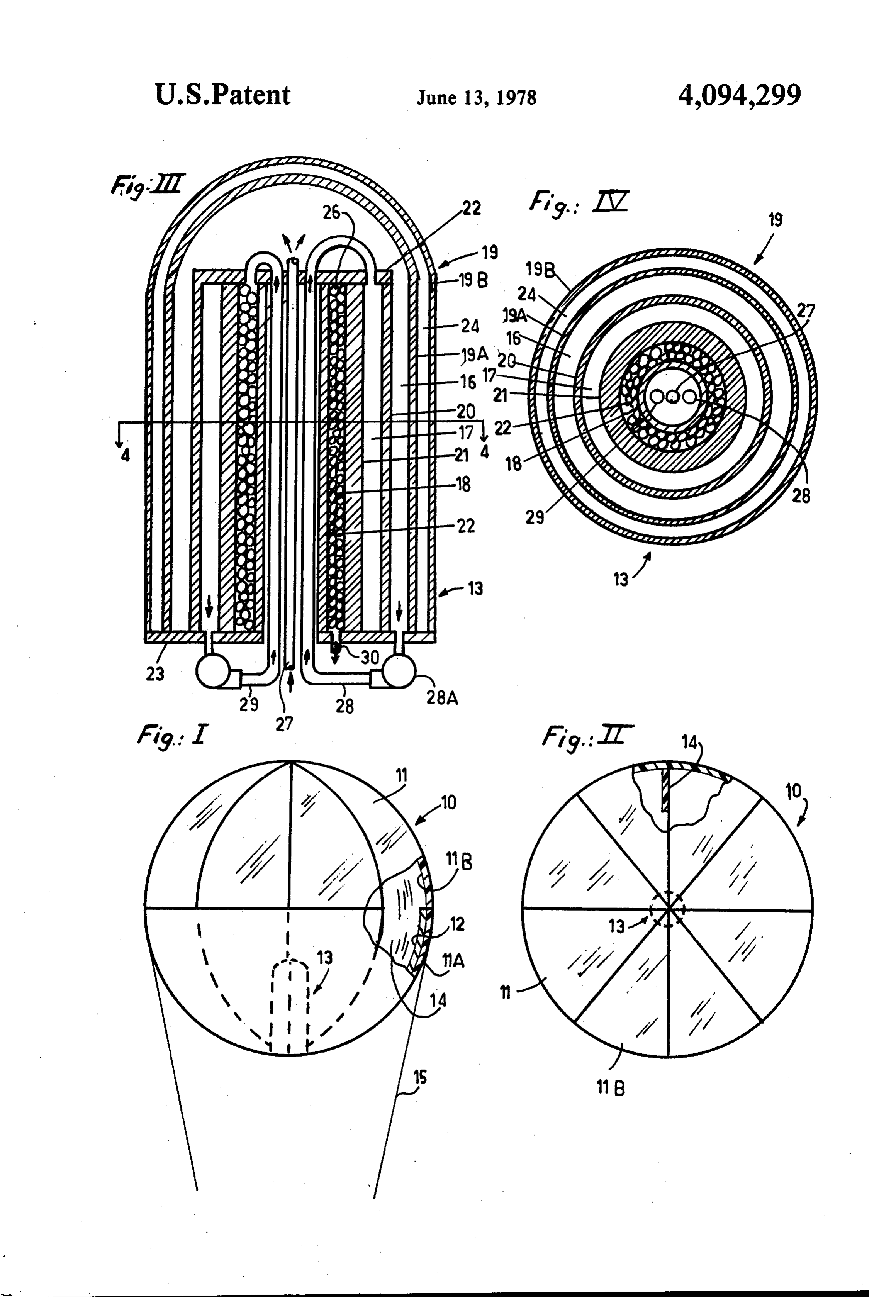
FIG. 4 is a plan sectional view taken along line 4-4
Page 2drawing sheetscan →
Page 3scan →
located so as to utilize the maximum available solare
HELIOTHERMODYNAMIC SYSTEM energy radiation.
PROBLEM Another feature resides in the provision of a solar boiler having a series of nested heating stages enclosed
Solar radiation it has been determined has a density of 5 in a thermo insulated light transmitting jacket wherein approximately 1394 watts per square meter with a possi solar energy is utilized to progressively increase the ble 2% variation before the process of atmospheric temperature and pressure of a working fluid under the absorption takes place, Meteorological conditions and condition of maximum solar radiation density, other factors reduce the obtainable solar radiation den Another feature resides in the provision offloating a sity to less than 300 watters per square meter on less 10 ballon having a concentrating heliostatic surface above than 2500 hours per year with the known type of solar the atmospheric solar absorbing layers and concentrat heating devices for the reason that the present solar ing the solar energy on a solar boiler for heating a work heating devices are built and constructed close to the ing fluid in successive stages.
earth's surface. For this reason, the known solar heating The foregoing features and other advantages will devices cannot be subjected to the maximum solar radi 15 become more readily apparent when considered in view ation density. Thus the effectiveness of the known solar of the drawings and specification in which: heating devices is limited to that solar energy which is FIG. 1 is a side elevation view of a heliothermody not lost by atmospheric absorption and/or meteorologi namic system embodying the present invention. cal amount of the total obtainable solar radiation den FIG. 2 is a top view of FIG. 1. sity. 20 FIG. 3 is a vertical sectional view of a solar boiler OBJECTS utilized in the present invention.
FIG. 4 is a plan sectional view taken along line 4-4
It is an object of this invention to produce aheliother on F.G. 3.
modynamic system constructed so as to utilize the maxi DETALED DESCRIPTION mum available solar radiation density. 25
Another object is to provide a solar heating device Referring to FIGS. 1 and 2, there is shown a helio which can be located over largely populated densities thermodynamic system 10 embodying the present in so as to be close to the point of consumption of the vention. The system or apparatus 10 comprises a bal energy produced thereby. loon 11 which comprises a lower hemispherical portion Another object is to provide a solar energy absorp 30 11A which is lined or coated with a reflecting surface tive boiler capable of utilzing the limitless concentration 12. The upper portion or half 11B of the ballon is of solar energy to achieve the maximum techncially formed of a light transmitting or transparent material. feasible temperature and pressure of a working fluid. In the illustrated embodiment the ballon 11 is formed Another object is to provide a heliothermodynamic of a suitable plastic material in which the bottom por system, which includes a ballon suspended above the 35 tion 11A may be mirror coated by well known coating atmospheric absorption layer of solar energy and con techniques, e.g., metallizing, etc. The upper portion 11B centrating the high density solar radiation onto a solar is formed of a clear or transparent material so as to boiler disposed within the balloon. permit the insident solar radiation to impinge onto the Another object is to provide for the harnessing of coated reflecting surface 12 whereby the solar radiation solar energy above the clouds where the losss of solar 40 is reflected in a concentrated manner toward an absorp energy by atmospheric absorption is the least, tion device; e.g., a solar boiler 13 as will be hereinafter BRIEF SUMMARY OF INVENTION described. The balloon thus described defines a solar energy concentrating heliostatic mirror which is gener
The foregoing objects and other features and advan ally spherice or spheroid in shape.
tages are attained by a heliothermodynamic system 45 To provide for additional structional stability, the which includes a balloon having a spherical or elliptical interior of the balloon 11 can be reinforced by webs or configuration having an upper light transmitting por sectors 14 which are spaced about the vertical axis of tion and a lower light reflective portion. The light trans the balloon. It will be noted that the webs or sectors 14 mitting portion permits solar radiation to penetrate are cresent shaped and need only to extend a fractional inside the balloon whereupon the solar radiation is re 50 amount toward the central vertical axis. flected in a concentrated manner by the reflective lower It will be understood that the balloon can be inflated portion onto an absorption device or heat receiver. with a lighter than air gas so that the balloon can be The heat receiver comprises a solar boiler having a floated or suspended above the earth and at an elevation series of nested heating stages for progressively increas where atmospheric absorption of solar energy is re ing the temperature and/or pressure of a working fluid 55 duced to a minimum, Suitable cables 15 or other means as the fluid is successively circulated through the re are provided for maintaining the balloon in position spective stages. Each stage includes a light transmitting relative to earth.
outer wall and wherein the innermost stage has dis With the construction described, it will be noted that posed therein a solar absorption material. The nested the balloon can be varied in size depending upon the stages in turn are enclosed in a low absorptive, light 60 amount of solar energy required for a particular appli transmitting insulated jacket so as to minimize any heat cation. Thus balloon of exceeding large proportions are loss while achieving maximum light transmitting there contemplated and/or feasible, e.g., balloons having through. diameters of hundreds and/or thousands of feet. FEATURES The balloon type of heliostatic mirror described not 65 only has an economical advantage over the known
A feature of this invention resides in the provision of forms of concentrating helistats, it is also made to float a system for harnessing solar energy wherein relative over the power consumming centers and above the large concentrating heliostat reflecting surfaces can be atmospherice absorption centers.
Page 4scan →
FIGS. 3 and 4 illustrate a heat absoption device or From the foregoing it will be noted that the tempera solar boiler 13 which is disposed within the balloon. As ture and pressure of the working fluid is the least in the shown, the solar boiler 13 comprises a plurality of first stage. Accordingly, the wall thickness of the walls nested stages wherein the working fluid can be heated 19A and 20 defining the first stage is the least in thick in progressive stages by the concentration of solar radi 5 ness of the respective walls; and therefore, reduces solar ation thereon. In the illustrated embodiment the solar radiation absorption to a minimum. Also since the first boiler 13 has three heating stages, e.g., 16, 17, and 18; stage is subjected to the lowest temperatures, a mini which stages are all enclosed or encased within a mum of heat loss is effected thereby. Also the arrange thermo insulated jacket means 19 formed of a good light 10 ment is such that the first stage will absorb the heat transmitting and low solar adsorption material, e.g., losses from the innermost stages. Since the thermal loss glass, silica and the like. is confined in the first stage, the wall thickness of wall As shown, the respective heating stages 16, 17, and 18 21 of the second stage can be increased so that the pres are defined by concentrically disposed cylinders, e.g., sure of the working fluid can be incremented while the glass cylinders wherein the first stage 16 is defined by 15 pressure differential acting on the common wall 20 the inner wall 19A of the thermo jacket means 19 and between the first and scond stage can be minimized. The the outer most concentric cylinder wall 20. The second outer wall 22 of the third or innermost stage 18 can be reduced in thickness so as to be commensurate with the stage 17 is defined by the annular space formed between cylinder walls 20 and 21. The third stage 18 is defined pressure of the working fluid in the third or innermost stage as the pressure of the fluid in the third stage acts by the space formed between cylinder walls 21 and 22. 20
As shown, cylinders 20, 21 and 23 which define the thereon with a compressive force. As the incident solar second and third stages 17 and 18 are connected be or radiation is completely absorbed within the innermost tween end plates 22 and 23. Enclosing the concentric transfer third stage 18, and due to the large ratio of heat cylinders 20, 21 and 22 is the thermo insulated jacket peraturesurfaces, the fluid is heated to its highest tem and pressure within stage 18.
means 19. The jacket means includes spaced apart 25 The end plates 22 and 23 can be formed of glass, jacket members 19A and 19B to define a vaccum space metal or composite or chamber 24 of negative pressure therebetween. It plates 22 and 23 is materials to and the function of the end withstand and contain the fluid will be understood that the vaccum chamber 24 and stages 16, 17, and 18 are sealed fluid tight with respect pressure in the various stages 16, 17, and 18, and to compensate for any thermal expansion of the various to one another. 30 cylinders.
In accordance with this invention, the jacekt means is The vaccum jacket means 19 enclosing the heating composed of jacket members 19A and 19B that are stages further assures a minimum of heat loss from the formed of good light transmitting and low absorption first stage 16.
material, such as glass so as to permit concentrated solar From the foregoing it will be noted that the wall radiation penetration therethrough. The respective cyl 35 thickness; temperature and pressure of the respective inders 20 and 21 are also formed of good light transmit stages increase toward the inside. By floating or sus ting material such as glass. Wall 22 may be formed of glass or any other type of material including metal since pending the balloon above the absorbing atmosphere maximum utilization of solar radiation can be achieved it is not necessary that wall 22 be formed of a light to heat the working fluid circulating through the re transmitting material.
Disposed in the space defining the third stage 18 there spective stages of the solar boiler 13. Also, the lower hemisphere 11A of the balloon 11 defines a heliostatic is disposed a radiation absorption material, e.g., glass mirror enabling the reflection of the maximum amount pebbles, fritters or dark bodies 26 to form a porous or of solar energy in a concentrating manner onto the solar open structure having a large ratio of heat transfer sur boiler 13.
face and which functions to absorb insident solar radia 45 tion. The large ratio of heat transfer surfaces thus also to While the invention has been described with respect a particular embodiment, it will be understood that functions to maximize the thermal exchange between variations and modifications may be made without de the working fluid and the absorption material 26. parting from the spirit or scope of the invention. The working fluid is introduced into the first stage by While the embodiment described is desired to be a conduit 27 extending through the innermost cylinder 50 floated above the absorptive layers of the atmosphere, it 22. In operation the partially heated working fluid in the will be understood that the balloon heliostat can func first stage 16 is circulated to the second stage by inter connecting pipe means 28. A pump 28A is disposed in tion while at lower elevations and/or on earth. However, effective, the density of solar radiation being pipe 28 to provide for positive circultion of the working concentrated thereby will be reduced as the balloon is fluid from the first stage 16 to second stage 17. Thus the 55 located closer to earth.
partially heated fluid of the first stage is further heated What is claimed is:
in the second stage. The fluid from the second stage 17 1. A heliothermodynamic system for harnessing solar can be further heated by circulating the fluid of the energy comprising:
second stage to the third stage by means of intercon a balloon adapted to be floated in the upper reaches of necting conduit 29. 60 the atmosphere where the atmospheric absorptions The heated fluid from the third stage is then directed of solar energy is minimized, by means of an outlet pipe 30 to a suitable power source, means for maintaining said balloon inflated, e.g., a turbine electric generator (not shown) to produce means for maintaining said balloon in spaced relation electric energy. While the illustrated embodiment illus ship relative to earth, trates the working fluid being progressively heated in 65 said balloon having a transparent portion for trans three stages, it will be understood that the number of mitting solar light into the interior of said balloon, stages can be varied depending upon design consider a light reflector covering an internal portion of said ations of the system 10. balloon opposite said transparent portion for con 5 centrating the incident reflected solar radiation said solar boiler including a pair of spaced apart end toward a focal area thereof, plates, and a heat receiver located in the focal area of said a plurality of nested spaced apart tubular members light reflecting portion of said balloon, interconnected between said end plates to define said heat receiver comprises a solar boiler having a said plurality of nested heating stages, plurality of nested, serially connected heating means for serially connecting said nested stages into stages including an inner most stage and an outer communication with one another, most stage, and solar radiation absorption means a solar radiation absorptive means disposed in the innermost disposed in said innermost stage of said nested heat 10 means for serially stage of said nested stages, ing stages, connecting said outermost heating stage in communication with the outermost stage and a light transmitting jacket means enclosing said of said nested heating stages, nested stages to define an outermost heating stage, means for introducing a working fluid into said outer surrounding said nested stages, most stage, said jacket means including a pair of spaced apart 15 means for circulating said working fluid serially light transmitting jackets wherein the space be through each of said connected stages whereby tween said jackets defines an area of negative pres said fluid is progressively heated as it flows Ste. through each said stage.
2. A heliothermodynamic system for harnessing solar 3. The invention as defined in claim 2 wherein said energy comprising: working fluid is progressively pressurized at it flows a balloon adapted to be floated in the upper reaches of through each said stage.
the atmosphere where the atmospheric absorptions means 4. The invention as defined by claim 3 wherein the of solar energy is minimized, for serially connecting the nested heating stages means for maintaining said balloon inflated, extend through the innermost member of said nested 25 members.
means for maintaining said balloon in spaced relation 5. The invention as defined in claim 2 wherein said ship relative to earth, jacket means and the tubular members of said solar said balloon having a transparent portion for trans boiler are formed of glass.
mitting solar light into the interior of said balloon, 6. The invention as defined in claim 2 wherein said a light reflector covering an internal portion of said 30 nested tubular members comprise spaced apart concen balloon opposite said transparent portion for con trically disposed cylinders, centrating the insident reflected solar radiation said cylinders defining nested annular heating stages, toward a focal area thereof, and said means for introducing said working fluid and a heat receiver located in the focal area of said into said outermost heating stage extending light reflecting portion of said balloon, 35 through the innermost member of said nested mem said heat receiver comprises a solar boiler having a bers.
7. The invention as defined in claim 2 wherein the plurality of nested, serially connected heating wall thickness of the respective nested stages increase in stages, and a light transmitting jacket means enclsoing said most stage.from the outermost stage toward the inner thickness nested stages to define an outermost heating stage, 8. The invention as defined in claim 2 and including surrounding said nested stages, solar radiation absorption means disposed in the inner said jacket means including a pair of spaced apart most stage of said nested stages to present optimum light transmitting jackets wherein the space be surface area to maximize thermal exchange with the tween said jackets defines an area of negative pres 45 working fluid.
Provenance
- Collection
- Patents citing this work
- Pages
- 5
- Method
- pdftotext (the PDF's own text layer) + pdftoppm 300dpi page scans
- Patent office record
- patents.google.com →
- Source
- Google Patents citing-documents table
- Assignee
- Percy Voelker
- Published
- 1978-06-13
- Transcribed from
- patentimages.storage.googleapis.com →