

patent · US3960136A
Solar energy collection system
1 June 1976
Text
Page 1bibliographic recordscan →
United States Patent 19 Moan et al.
54 SOLAR ENERGY COLLECTION SYSTEM
(75 Inventors: Kenneth L. Moan; Yu Kun Pei, both of Toledo, Ohio 73 Assignee: Owens-Illinois, Inc., Toledo, Ohio
52 U.S. Cl................................. 126/271; 237/1 A;
(5) Int. Cl.’............................................. F24, 3/02
UNITED STATES PATENTS
980.505 1/911 Emmet................................ 126/27 1068,650 7/1913 Harrison ............................. 26/271 1951,403 3/1934 Goddard............................. 26/27 | 2,205,378 6/1940 Abbot........ .................. 26/27 | 2,553,073 5/195 Barnett............................... 126/27 | 3,390,672 7/1968 Snelling.............................. 26/27
Primary Examiner-Kenneth W. Sprague
Assistant Examiner-James C. Yeung
Attorney, Agent, or Firm-Steve M. McLary; Edward
J. Holler
A system for the collection and utilization of solar en ergy. A manifold is mounted on the roof of a building with a major portion of the manifold being contained within the building. A plurality of double-walled, glass solar energy collector tubes are inserted into that part of the manifold which extends above the roof of the building. A gas, such as air, completely fills the mani fold and collector tubes. The gas is circulated from the manifold to the ends of the collector tubes from whence it returns, having been heated during the movement. A heat exchanger mounted in the manifold has a working fluid, such as water, passing through it. The heated gas impinges on the heat exchanger, giving up much of its energy to the fluid passing through the heat exchanger. The working fluid is then used for space heating or cooling functions within the building. 6 Claims, 4 Drawing Figures
Drawings
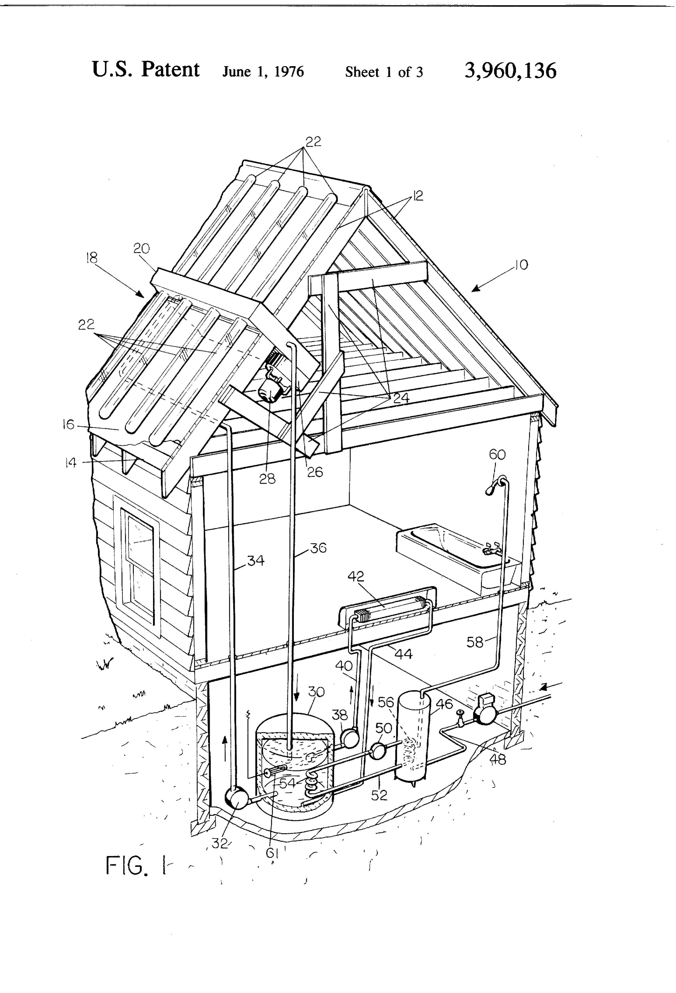
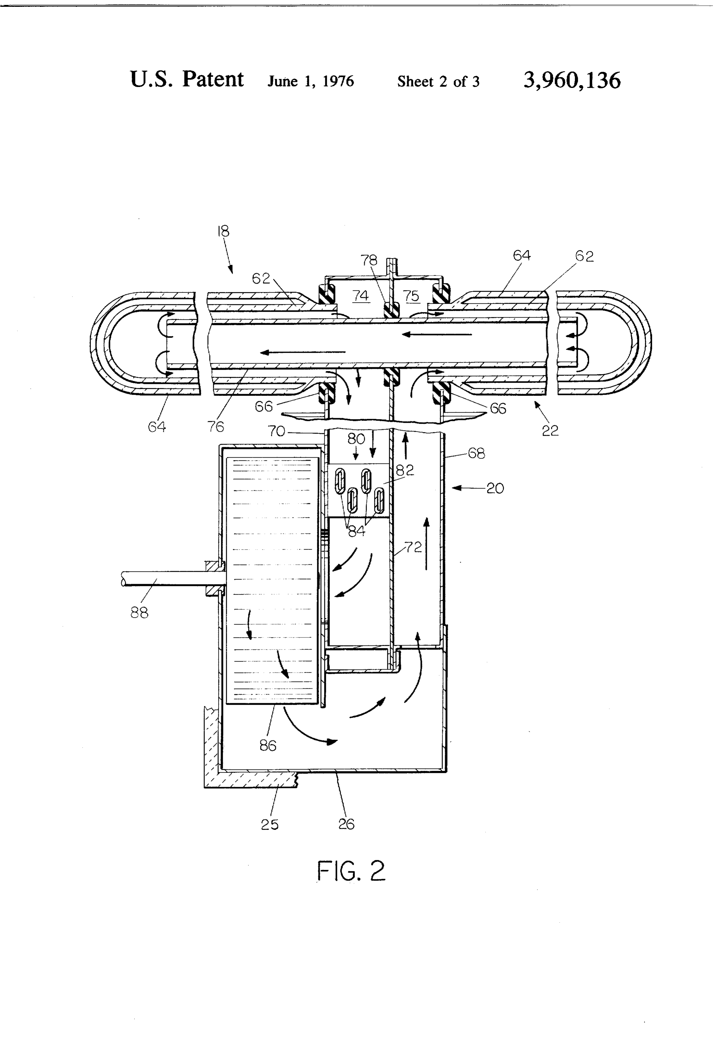
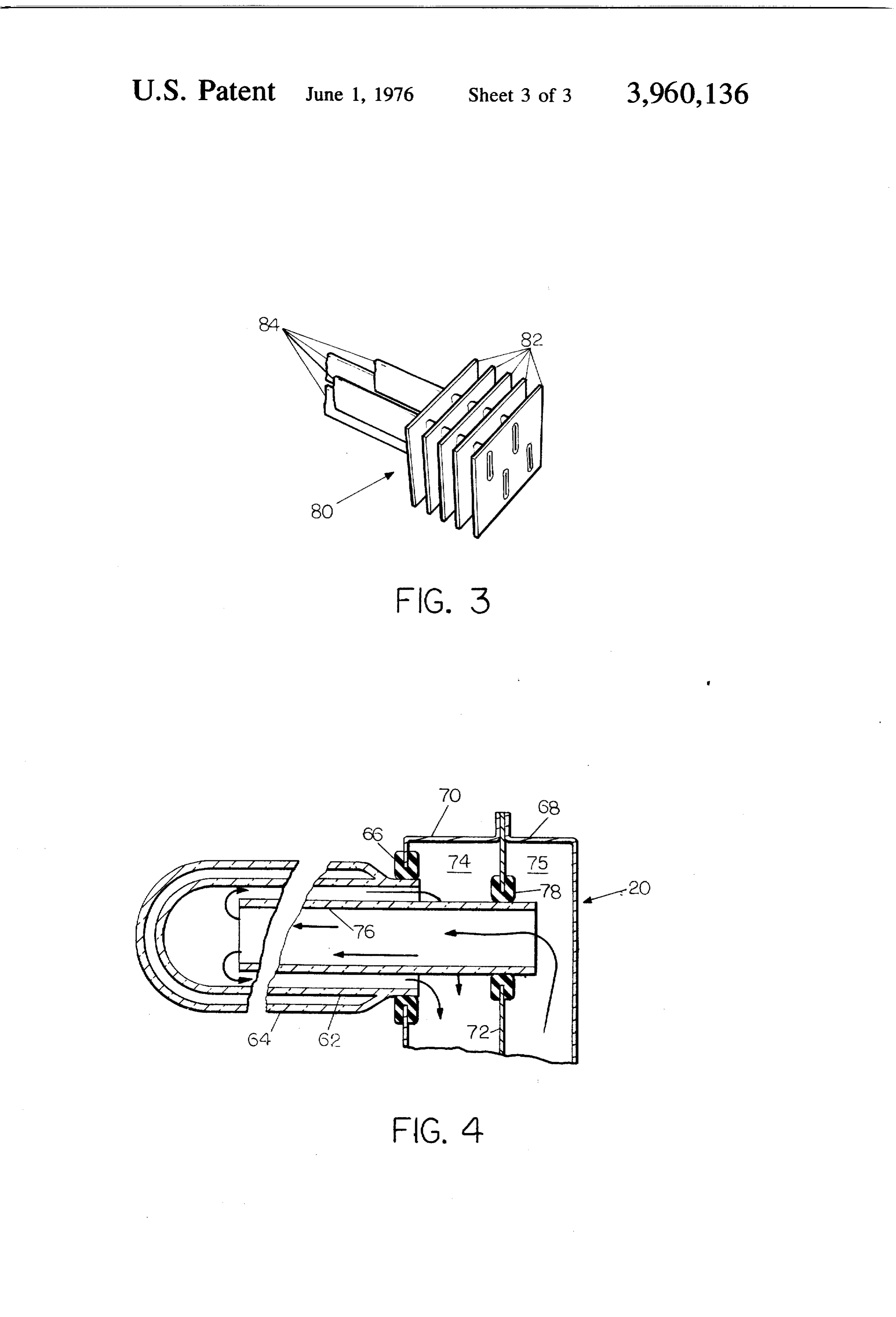
FIG. 1 is a perspective view, partially cut away, of a structure which utilizes the solar energy collector of the present invention;
FIG. 2 is a side elevational view, in cross-section, of the solar energy collector of the present invention, FIG. 3 is a perspective view of a portion of a typical heat exchanger configuration useable with the present invention; and
FIG. 4 is a side elevational view, in cross-section of a modification of the solar energy collector shown in
Page 2drawing sheetscan →
Page 3drawing sheetscan →
Page 4drawing sheetscan →
Page 5scan →
Solar energy collection system
Background of the invention
This invention generally relates to solar energy col- 5 lectors. More specifically, this invention relates to solar energy collectors using double-walled glass tubes which are the major energy collection elements. Precisely, this invention relates to a solar energy collector of the type described which includes a heat exchanger in a gas 10 filled manifold to allow use of air as an energy collec tion medium without requiring bulky air duct-work. Most solar energy collectors of the prior art are of the flat plate type wherein air or water is circulated to absorb solar energy. Despite some advantages of flat is plate collectors, glass, tubular collector arrays offer manufacturing and installation economies, In addition, air has seldom been used as the medium for extracting the solar energy from the collector array, whatever the type, for a number of reasons. If air is to be used to 20 convey the solar energy elsewhere within a building for utilization, a bulky and expensive duct-work system is required. In addition, large volumes of air must be moved which require significant energy for pumping power. Flat plate collectors which use water for energy 25 collection also have some deficiencies. The amount of water on the roof at any time is significant, thus creat ing a weight load factor problem. Water in such large quantities in a thin film is subject to freezing, unless anti-freeze solutions are used. A leak in such a system 30 would liberate a large quantity of water on the roof where seepage into the structure could become a prob lem. In addition, these systems can seldom meet boiler codes, so the advantages inherent in operating at ele wated pressures are not available. We have invented a 35 solar energy collector which has a plurality of double wall glass tubes connected to a manifold on the roof of a building. Air is circulated through the tubes and man ifold to be heated by the sun. The pumping power and volume of air flow are relatively small. A heat ex 40 changer carries water through the manifold. The water is heated by the circulating air. There is, therefore, only a small amount of water on the roof at any time, the heat exchanger can meet boiler codes, and the heated 45 water may be transported within the building for utili zation in relatively small water pipelines. Examples of the prior art may be seen in the following U.S. Pat. Nos.
Summary of the invention
Our invention is a solar energy collector. The solar energy collector includes a manifold which is divided into at least a first and a second separate compartment. 55 A tube connects the first compartment with the second compartment and extends beyond the second compart ment into the outside atmosphere. A double-wall glass tube, the outer wall thereof being transparent about substantially its entire circumference, has the space 60 between the double walls sealed at a sub-atmospheric pressure. The double-wall tube has a closed end and an open end which envelopes the connecting tube and which is in communication with the second compart ment of the manifold. A gas fills the manifold, the con necting tube and the interior of the double-wall tube. A 65 means is provided for propelling the gas, in an endless cycle, from one compartment, through the connecting tube, through the double-wall tube interior in counter flow to the original path through the connecting tube, and into the other compartment of the manifold. A heat exchanger is mounted in the path of flow of the gas from the second compartment into the first compart nent.
Brief description of the drawings
FIG. 1 is a perspective view, partially cut away, of a structure which utilizes the solar energy collector of the present invention;
FIG. 2 is a side elevational view, in cross-section, of the solar energy collector of the present invention, FIG. 3 is a perspective view of a portion of a typical heat exchanger configuration useable with the present invention; and
FIG. 4 is a side elevational view, in cross-section of a modification of the solar energy collector shown in
Detailed description of the drawings
FIG. 1 illustrates a building 10, in this case a private residence, which is heated by the solar energy collec tion system of the present invention. The roof structure of the building 10 is formed as is conventional practice with a plurality of rafters 12. The rafters are then cov ered with roofing boards 14 and then covercd with shingles 16. On one side of the roof, preferably facing in a southerly direction, is mounted a solar energy collector 18. The solar collector 18 includes a manifold 20 which is built into the roof structure and actually interrupts the rafters 12 on the side where the solar energy collector 18 is mounted. The manifold 20 is designed to be a structural member and a part of the roof, and as may be easily seen in FIG. 1 extends par tially above the roof line or above the shingles 16 but has a major portion thereof extending into the attic portion of the building 10. The solar energy collector 18 also includes a plurality of collector tubes 22 which are carried by that portion of the manifold 20 which extends above the roof structure. While the manifold 20 is shown as mounted transversely to the roof struc ture, it could be mounted longitudinally between the rafters 12. A longitudinal mounting has the advantage of creating less shading effects between individual col lector tubes 22 and of being less sensitive to seasonal variation in the declination of the sun. However, such a mounting orientation has the drawback of being sensi tive to the cosine effect of direct solar radiation at low sun angles early and late in the day. On balance, the transverse mounting of the manifold 20 is preferred as affording maximum solar energy collection potential under a variety of sun orientation. The solar energy collector 18 is shown in greater detail in FIG. 2 and will be discussed further with respect to FIG. 2. Note that because of the interruption of the rafters 12 at the point where the manifold 20 is inserted, it is necessary to provide additional structural framing members for the roof. These framing members generally designated as 24 are simply shown as one illustrative technique of increasing the strength of the roof as required by break ing the rafters 12 on one side of the roof. The working fluid within the solar energy collector 18 is a gas, pref erably air which thus avoids the problems of making the entire solar collector 18 completely gas-tight to avoid leakage of dangerous or expensive gases which could also be used as the working fluid. A blower hous ing 26 contains a blower or fan driven by a motor 28 to circulate air within the manifold 20. The heat exchange 6 fluid which receives energy from the working fluid collector 18 illustrated in FIG. 2 combines the best within the manifold 20 is preferably a liquid, such as features of the water systems and the air systems to water. The liquid is contained within a heavily insulated achieve an optimum result. The collector tubes 22 may tank 30 which may be mounted in a convenient loca be seen to be double-walled glass tubes. The inner and tion of the building 10. The tank 30 is shown as being outer tubes 62 and 64 respectively of the collectors 22 in the basement portion in FIG. 1, but could also be are sealed together and the space between the tubes 62 mounted in the attic or on the roof of such a building. and 64 is evacuated. This evacuated space acts as a Liquid to be heated is pumped from the lower portion very significant heat-transfer barrier and prevents loss of the tank 30 by a pump 32. This, of course, is done O of solar energy once collected within the collectors 22. simply because the coolest liquid in the tank 30 will As may be seen, the outer tube 64 terminates slightly always be near the lower portion of the tank 30. The before the open end of the collectors 22, and thus liquid so pumped passes through a pipeline 34 to one allows the inner tube 62 to be plugged into sealing end of the manifold 20. Within the manifold 20, as will engagement with gaskets 66 which are placed in open be shown in FIG. 2, is a heat exchanger which then ings formed in the manifold 20. Depending upon manu allows the heated gas within the manifold 20 to pass its 5 facturing considerations, either the inner tube 62 or the energy to the liquid flowing through the heat ex outer tube 64 may be plugged into the manifold 20. changer. After the liquid has been heated, it emerges The manifold 20 is preferably made in three separate from the manifold 20 in a pipeline 36 which then enters segments. There are two complementary U-shaped box the top of the tank 30. Thus over a period of time, the 20 members 68 and 70. The members 68 and 70 generally liquid contained within the tank 30 may be circulated assume the configuration of a closed box with an open through the manifold 20 a number of times picking up top. In assembly, the two open sides of the members 68 heat energy during each passage. The temperature of and 70 are placed together to form a completely closed the liquid within the tank 30 therefore begins to rise structure. Before this is done, however, a center divider and may be held at a fairly high level on an average day 72 is placed in position and is secured to thereby form with sunlight available to heat the gas contained within 25 two separate compartments 74 and 75. Since the mani the solar energy collector 18. The heated liquid held fold 20 has no water flowing directly through it, the within the tank 30 may be used for space heating pur manifold 20 could be made of a foamed plastic insulat poses within the building 10. To illustrate this use, a ing material. One of the collector tubes 22 is plugged single space-heating loop has been shown. The heated 30 into the compartment 74 while on the opposite side liquid is removed from the top of the tank 30 by a pump another collector tube 22 is plugged into the compart 38 and pumped upwardly through a pipeline 40 to a ment 75. This arrangement obtains throughout the conventional radiator or heat exchanger 42. The entire length of the solar energy collector 18 as is best heated liquid then gives off heat energy into the interior seen in FIG. 1. Thus there are a plurality of collector of the building 10 and the cooled liquid then returns 35 tubes 22 in communication with the compartment 74 through a pipeline 44 into the lower portion of the tank and a corresponding plurality of collector tubes 22 in 30. The heated liquid within the tank 30 may also be communication with the compartment 75. The mani used to furnish service hot water for use within the fold 20 and blower housing 26 have all of their exposed residence 10. A service hot water-holding tank 46 is surfaces covered with an insulating material 25. This furnished with water from the city water supply or from 40 material 25 is shown on only a portion of these surfaces a private pump through an inlet pipeline 48. A pump 50 in FIG. 2 to avoid undue complication. The insulating circulates a heat exchange medium, again preferably material 25 keeps heat losses from the manifold 20 to a water, in a closed loop 52 between the tank 30 and the minimum. A relatively long connector tube 76 is en hot water tank 46. The pipe 52 has a plurality of coils gaged in a gasket 78 which is placed in an opening in 54 in the tank 30 and a corresponding plurality of coils the center divider 72. The opening in the center divider 56 in the hot water tank 46. Thus the water contained 45 72 in which the gasket 78 is placed, is completely within the hot water tank 46 will be heated over a sealed by the outer walls of the connector tube 76. The period of time by the passage of the liquid contained in connector tube 76 as was noted is a relatively long tube the closed loop pipeline 52 between the tank 30 and and extends outwardly almost to the end of the collec the hot water tank 46. The hot water within the tank 46 tor tubes 22 which connect both the compartment 74 may then be used for general purposes within the resi SO and the compartment 75. Thus the collector tubes 22 dence 10, as illustrated by a pipeline 58 which is con are paired in the sense that one tube 22 is in communi nected to a shower head 60. The tank 30 may have an cation with the compartment 74 while an opposite tube auxiliary electrical heater 61 provided for periods when 22 is in communication with the compartment 75. The sunlight is not available. connector tube 76 then extends nearly the full length of FIG. 2 illustrates in a much more detailed form the 55 both of these tubes. There is, therefore, a path available precise configuration of the solar energy collector 18 of for air within the manifold 20 which allows air to pass the present invention. One of the objections in the prior from the compartment 74 to the compartment 75 by art to solar energy collectors which used air as an oper flowing through the connector tube 76. The connector ational medium was the amount of power required to 60 tube 76 is shown in FIG. 2 as being a glass tube, but the move the air. Air is a relatively inefficient heat ex material of this particular tube is not especially critical. change medium because of the large volumes required However, it is preferable that one wall of the inner tube to transport significant quantities of heat. For this rea 62 be coated with a black or sun-absorbing coating so son, the ductwork and the pumping power were rela that the sunlight falling upon the inner tube 62 through tively large. On the other hand, the drawbacks to water the transparent outer tube 64 will heat the inner tube systems which use flat plate collectors or which had 65 62, thus extracting solar energy. A heat exchanger 80 is water on the roof was that such systems were subject to positioned within the compartment 74 and completely leakage, to freezing or to boiling if the temperature of fills the compartment 74 so that any air passing down the water reached too high a level. The Solar energy wardly in the compartment 74 must pass through the 7 heat exchanger 80. A particular configuration of a heat which shows the modification necessary to make the exchanger that is preferred is shown in a perspective collector array suitable for such use. All that is neces view in FIG. 3. The heat exchanger 80 preferably has a sary to make this modification is the elimination of the plurality of flat plates 82 attached to a plurality of 5 collector tubes 22 which would normally be connected elliptical pipes 84 through which the fluid contained into the compartment 75. Additionally, the connector within the tank 30 is pumped. If desired, the pipes 84 tube 76 is shortened since it no longer needs extend may be round. Because the liquid system is actually beyond the compartment 75. The numbering of FIG. 4 isolated from the solar energy collection system, the for identical components is the same as that shown in liquid system may be designed to meet boiler codes, FIG. 2. Thus it may be seen that the air circulation thereby allowing operation of a pressurized liquid sys pattern would be through the blower wheel 86 into the tem. This is a significant advantage since flat plate compartment 75 and thence down the connector tube collectors and the tubular glass collectors 22 of this 76 and out along the inner tube 62 into the compart invention usually cannot meet such code requirements. ment 74. The air would then pass over the heat ex The fluid is introduced into and removed from the changer 80 and again be pulled in by the rotating plurality of pipes 84 through inlet and outlet headers at 5 blower wheel 86. It may be seen that the modification either end of the manifold 20. Thus, as heated air flows shown in FIG. 4 results in a reduction to approximately over the plates 82, the plates 82 become heated and one-half of the total area available for the collection of transfer this energy into the fluid contained within the solar energy as compared with the array shown in FIG. pipes 84. Additionally, the same heated air can directly 1. However, the longitudinal extent of the entire array impact on the pipes 84 and impart heat directly by such 20 might be extended in such a case to result in no net loss direct contact. Because the bulk of the manifold 20, of available collector area.
and in particular the heat exchanger 80 through which What we claim is:
water flows, is below the roof in the attic of the building 1. A solar energy collector which comprises: 10, the danger of freezing the water is substantially 25 a manifold divided into at least a first and a second reduced if not completely eliminated. A blower wheel separate compartment;
or rotary air circulation means 86 is contained within a connecting tuba extending through said first and the blower housing 26, and is driven by a shaft 88 that said second compartments, said connecting tube is powered by the motor 28. The operation of the solar extending beyond both said first and said second energy collector 18 shown in FIG. 2 may be briefly 30 compartments into the outside atmosphere; explained as follows: Air is pulled out of the compart a first double wall transparent glass tube, the space ment 74, through an opening formed in the wall of the between said double walls being sealed at a sub compartment 74, by the rotating blower wheel 86. This atmospheric pressure, having a closed end, and an air then is passed through the lower portion of the open end enveloping that portion of said connect blower housing 26 and is forced into the compartment 35 ing tube extending beyond said second compart 75 through an opening in the bottom of the compart ment and in communication with said second com ment 75. By virtue of the pressure differential behind partment;
this air, the air is forced outwardly to the end of the a second double wall transparent glass tube, the inner tube 62 connected into the compartment 75 and space between said double walls being sealed at a then into and through the cross-connector tube 76. At 40 sub-atmospheric pressure, having a closed end, and the end of the cross-connector tube 76, the air exits an open end enveloping that portion of said con into the inner tube 62 which is in communication with necting tube extending beyond said first compart compartment 74 and flows down along the inner tube ment and in communication with said first com 62 and into the compartment 74. This air then flows partment;
through the heat exchanger 80 and is again pulled into the blower housing 26 by the rotating blower wheel 86. 45 a gas,first filling said manifold, connecting tube and said and second double wall tubes;
The length of the collectors 22 is calculated such that means for propelling said gas in an endless cycle from as the air that is being circulated in this pattern passes one compartment to the other, through said con through the collectors 22 and down the connector tube necting tube, through both of said first and second 76, the air experiences an appreciable rise in tempera 50 double wall tubes in counter flow to the path of ture. Thus the air which impacts upon the heat ex flow through said connecting tube and into the changer 80 is considerably hotter than the air which other compartment of said manifold; and enters into the inner tube 62 connected to the compart a heat exchanger, mounted in the path of flow of said ment 75. The air which has been heated gives up a gas from said second compartment to said first significant portion of its energy to the heat exchanger 80 thereby heating the fluid flowing through the ellipti 55 2. compartment.
The solar energy collector of claim 1 wherein said cal tubes 84. This cycle is continuously repeated with the fluid that is circulated from the tank 30 becoming means a for propelling said gas includes:
blower housing connected to said manifold and hotter and hotter as it makes multiple passes through having openings into said first and second compart the heat exchanger 80.
The availability of roof space for installation or the 60 ments, shape of a roof may dictate an array configuration a rotary gas circulation means mounted in said somewhat different from that shown in FIG. 1. For blower housing for moving gas from said second example, it may be possible to operate this system with compartment to said first compartment; and a plurality of collector tubes 22 extending from only 65 means for driving said rotary gas circulation means. one of the compartments 74 and 75. An example of 3. The solar energy collector of claim 1 which further such a collector is shown in FIG. 4. The operation of includes:
the collector unit would be identical to that shown in a layer of a heat insulating material surrounding all FIG. 2, so the view of FIG. 4 is a fragmentary view exposed surfaces of said manifold.
Page 8scan →
4. The solar energy collector of claim 1 which further includes:
an energy-absorbing, opaque coating covering sub stantially an entire surface of the inner wall of each 5 of said double wall glass tubes.
5. A solar energy collection system for a building, which includes a roof portion, which comprises, in combination:
a manifold, mounted on said roof portion and having () at least part of said manifold extending above said roof portion and part of said manifold within said building below said roof portion, said manifold being divided into at least a first and a second sepa a connecting tube extending through said first and said second compartments, said connecting tube extending beyond both said first and said second compartments and overlying a part of said roof 20 portion in the outside atmosphere;
a first double wall transparent glass tube, the space between said double walls being sealed at a sub atmospheric pressure, having a closed end, and an open end enveloping that portion of said connect 25 ing tube extending beyond said second compart ment and in communication with said second com partment;
A second double wall transparent glass tube, the space between said double walls being sealed at a sub-atmospheric pressure, having a closed end, and an open end enveloping that portion of said con necting tube extending beyond said first compart ment and in communication with said first com partment;
a gas, filling said manifold, connecting tube and said first and second double wall tubes, means for propelling said gas in an endless cycle from one compartment to the other, through said con necting tube, through both of said first and second double wall tubes in counter flow to the path of flow through said connecting tube and into the other compartment of said manifold;
a heat exchanger, mounted in the path of flow of said gas from said second compartment to said first compartment;
a fluid for circulation through said heat exchanger; means for storing said fluid within said building; and means for moving said fluid to and from said heat exchanger from said storage means.
6. The solar energy collection system of claim 5 which further includes:
an energy-absorbing, opaque coating covering sub stantially an entire surface of the inner wall of each of said double wall glassk tubes.
Provenance
- Collection
- Patents citing this work
- Pages
- 8
- Method
- pdftotext (the PDF's own text layer) + pdftoppm 300dpi page scans
- Patent office record
- patents.google.com →
- Source
- Google Patents citing-documents table
- Assignee
- Owens-Illinois, Inc.
- Published
- 1976-06-01
- Transcribed from
- patentimages.storage.googleapis.com →