

patent · US4044753A
Solar energy collection system
30 August 1977
Text
Page 1bibliographic recordscan →
United States Patent [191 [11] 4,044,753 Fletcher et a1. [45] Aug. 30, 1977
[54] SOLAR ENERGY COLLECTION SYSTEM 3,713,727 1/ 1973 Markosian et a1. ................ .. 126/271 3,892,433 7/1975 Blake ..................... .. 126/270 X [76] Inventors: James C. Fletcher, Administrator of 3,924,604 12/ 1975 Anderson ....... .. 126/270 the National Aeronautics and Space 3,979,597 9/1976 Ducker ... .. ... . .. . . . . .. 126/270 X
Administration, with respect to an invention of; M. Kudret Selcuk, La Primary Examiner—Kenneth W. Sprague
Canada, Calif. Assistant Examiner-Larry Jones
Attorney, Agent, or Firm-Monte F. Mott; Wilfred [21] Appl.No.: 681,096 Grifka; John R. Manning [22] Filed: Apr. 28, 1976 [57] ABSTRACT [51] Int. cm .......................................... .. F24J 3/02 A solar energy collection system including a plurality of [52] U.s.c1...... ............................. .. 126/271; 126/270; energy receivers supported in suspension by an array of 60/641; 52/117 radially extending booms above a ?eld of heliostats [58] Field of Search ............. .. 126/270, 271; 237/1 A; which serves to re?ect a plurality of beams of solar 353/3; 60/641; 52/116, 117, 643, 146, 120, 648, energy toward said receivers. Each of said receivers is 111; 212/58 A, 47 characterized by a curved target surface substantially [56] References Cited totally illuminated by the re?ected beam. A network of interconnected conduits for conducting a working ?uid
761,596 5/1904 surface of each receiver, whereby the working ?uid is 81 1,274 l/ 1906 heated for converting radiant energy to heat, and a 1,969,839 8/1934 network of conduits for collecting and conducting 2,307,737 1/ 1943 heated working ?uid away from the receivers.
3,466,119 9/ 1969 8 Claims, 10 Drawing Figures
f \ \ a £28m an ligaments;
Drawings
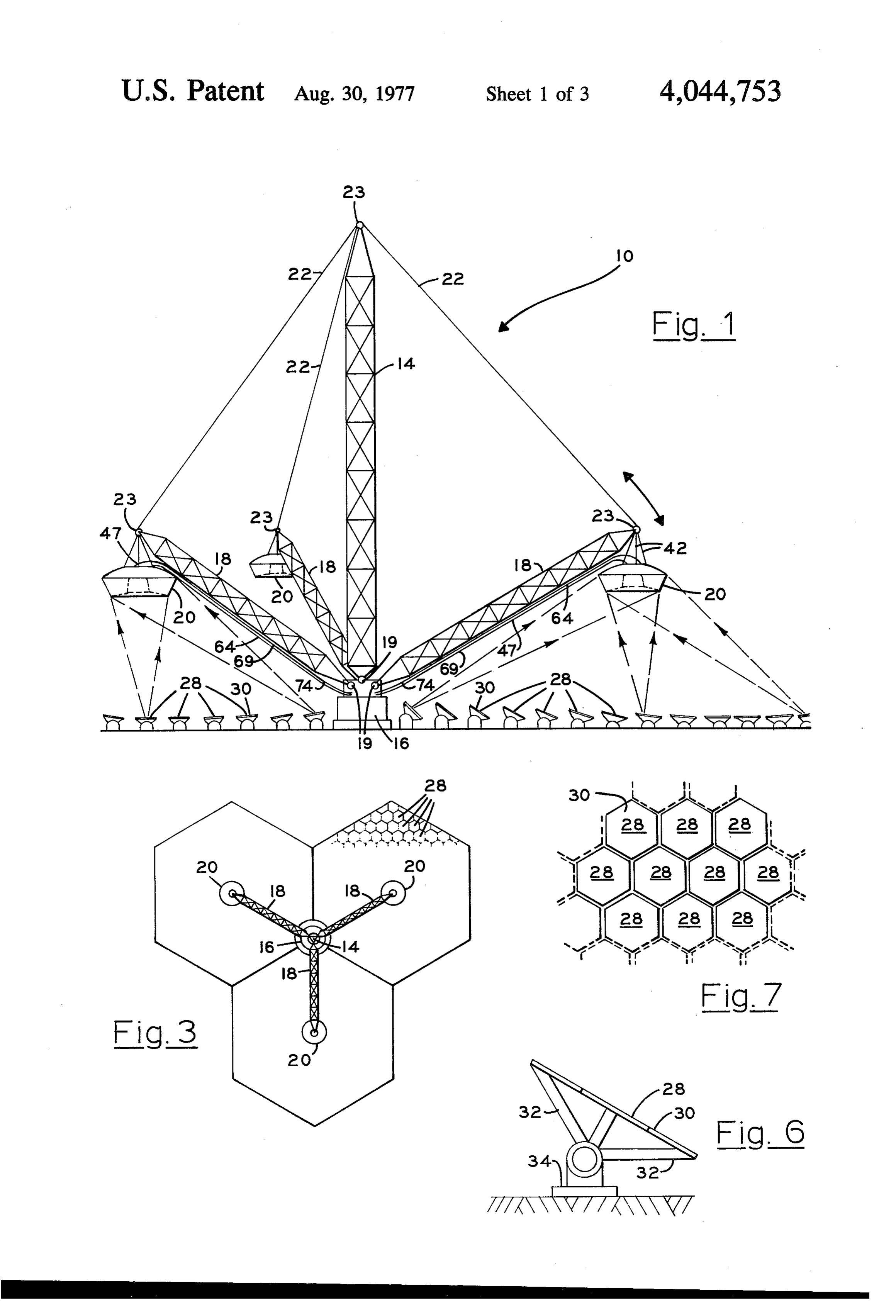
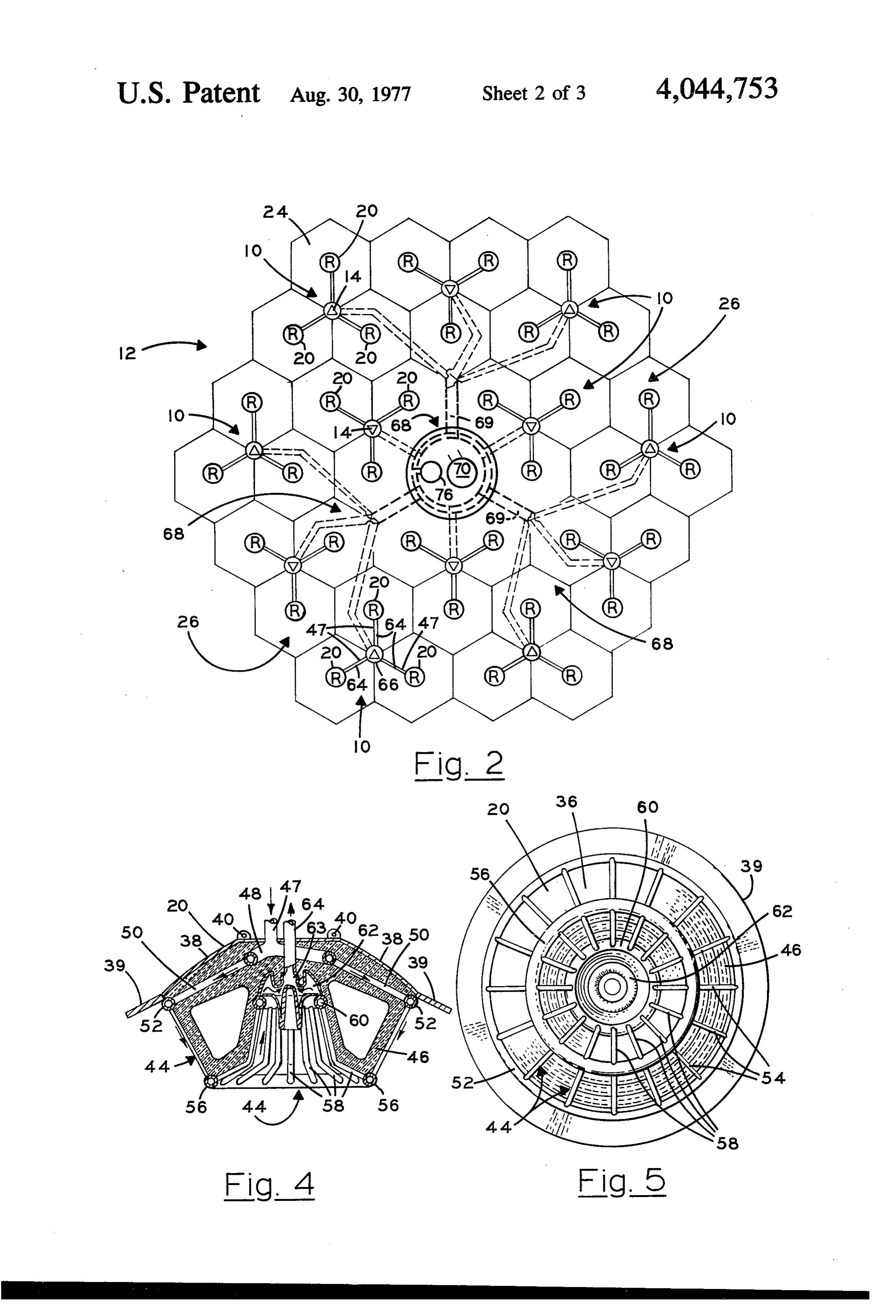
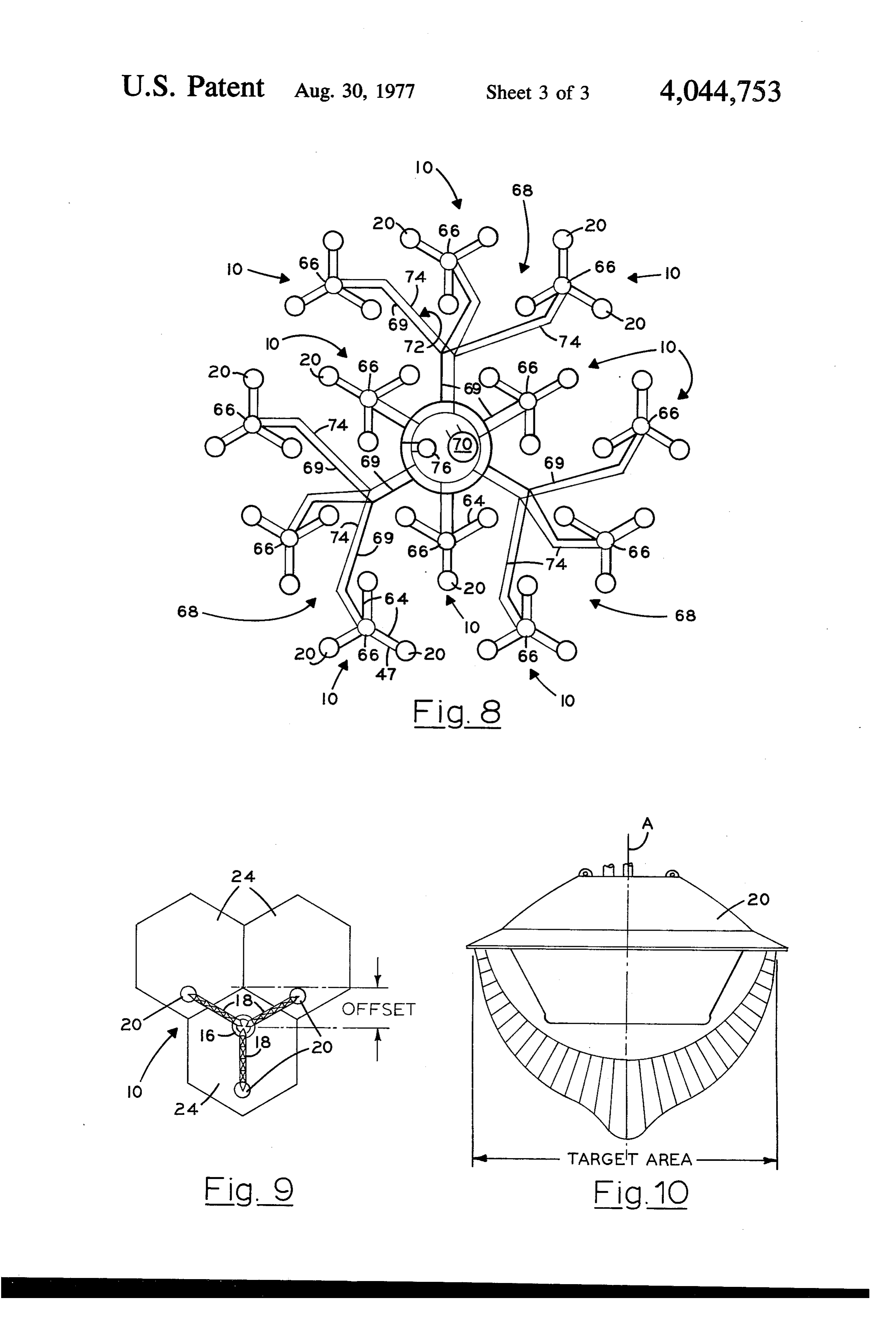
FIG. 10 is a schematic view depicting a ?ux distribu system particularly suited for use in collecting solar tion pattern for an incident beam of solar energy as it energy a receiver having a curved target surface for strikes the target surface of one of the receivers.
Page 2drawing sheetscan →
Page 3drawing sheetscan →
Page 4drawing sheetscan →
Page 5scan →
are mounted atop supporting towers for intercepting
SOLAR ENERGY COLLECTION SYSTEM beams re?ected from surfaces near the base of the tower. Although beams re?ected from the edges of a
ORIGIN OF THE INVENTION heliostat ?eld are characterized by good angles of inci The invention described herein was made in the per 5 dence, relative to the receivers, dispersion of the beams formance of work under a NASA contract and is sub due to pointing errors tend to dilute solar ?ux. Conse ject to the provisions of Section 305 of the National quently, a major portion of the ?ux ?eld established by Aeronautics and Space Act of 1958, Public Law 85-568 re?ected beams may be lost because of poor intercep (72 Stat. 435; 42 USC 2457). tion. This, of course, can be overcome, generally, by 10 increasing the relative size of the target area of the
BACKGROUND OF THE INVENTION receiver. However, an increase in the size of the target 1. Field of the Invention area tends to increase construction and maintenance The invention generally relates to solar energy con costs disproportionately to the increases realized in the version systems and more particularly to a collection level of the system’s ef?ciency. Moreover, precise uni system particularly suited for use in collecting solar formity in ?ux distribution normally is not obtainable. energy and converting the collected energy to other Hence, because of a lack of uniformity in ?ux distribu forms of usable energy such as thermal, electrical and tion an increase in temperature differentials occurring the like. across the system is experienced with an attendant re The sun, of course, comprises a substantially non duction in overall ef?ciency.
destructive source of energy available for continuous Another parameter which must be considered by exploitation. It has long been recognized that radiant designers of solar energy collection systems is wind solar energy can and should be utilized to a greater loading. In those geographical areas in which solar extent in order to reduce dependence upon fossil fuels as energy collection systems are used with greatest effec sources of usable energy. tiveness, a greater average wind-loading of supporting Unfortunately, those systems heretofore employed in 25 towers can be expected. Unfortunately, the towers collecting and utilizing solar energy generally lack ef? heretofore proposed generally are characterized by a ciency of an order of magnitude necessary for effec low strength-to-cost ratio. The criticality of this param tively competing with fossil fuels. Efforts to provide eter can be more fully appreciated when it is recognized new systems, as well as to improve existing systems and ‘that a failure of a single tower not only removes the techniques are continuously being made at all levels in 30 energy collection system from an on-line status, but attempting to acquire and utilize energy derived from inherently requires extensive repair at an inordinate solar sources at reduced costs. The likelihood of success expense.
of the efforts now being made depends largely upon the Finally, energy collection systems which employ cost effectiveness of the systems when employed in tower-mounted receivers supported above a heliostat collecting and converting solar energy to usable forms 35 field generally lack a capability for expansion, without of energy. redundant add-on facilities. Of course, redundant add 2. Description of the Prior Art on facilities necessitate excessive expenditures of capi One direction taken in attempting to enhance cost-ef tal.
fectiveness encompasses a use of a ?eld of heliostats It should, therefore, be apparent that there currently comprising a plurality of re?ective surfaces, each hav 40 exists a need for a simple ef?cient system through which ing a capability for concentrating a beam of solar en solar energy can be collected and converted to a usable ergy on a collector equipped with an energy conversion form and utilized more effectively, ef?ciently, and eco unit adapted to collect and convert radiant solar energy nomically.
to usable forms of energy such as electrical and thermalIt is, therefore, the general purpose of the instant forms. Those engaged in the search for systems and 45 invention to provide an improved energy collection techniques capable of collecting and converting solar system particularly suited for use in collecting energy energy at reduced costs can readily appreciate that the from solar sources, characterized by a simple, eco prior art contains numerous descriptions of systems nomic, and efficient combination of improved receivers, which employ re?ector and receiver combinations supported by an improved array of radially oriented through which radiant solar energy is concentrated and 50 booms above an improved ?eld of heliostats, whereby converted to a more usable form of energy, such as the ef?ciency and cost effectiveness of radiant energy electrical or thermal energy. collection systems generally are enhanced. The prior art energy collection systems are character ized by centralized energy receivers which capture OBJECTS AND SUMMARY OF THE concentrated beams of radiant energy directed toward 55 INVENTION the receivers by solar energy reflectors. One such sys It is, therefore, an object of the instant invention to tem utilizes energy receivers supported on a tower provide an improved solar energy collection system. above an array of energy re?ectors, such as a heliostat It is another object to provide an improved solar ?eld. Unfortunately, a signi?cant loss of ground area energy collection system having enhanced energy col attends the use of such a system. As can be appreciated lection and conversion capabilities. the loss is occasioned by the space occupied by the baseAnother object is to provide an energy collection system particularly suited for use in collecting solar for the tower, as well as by the space normally occupied by the heliostat ?eld utilized for re?ecting incident energy at reduced costs and increased ef?ciency. beams of radiant solar energy toward the receivers. It is another object to provide an energy collection Where re?ectors are mounted near the base of a 65 system characterized by a magnitude of ef?ciency suit tower, the attendant loss of area, of course, is minimal. able for effectively competing with systems employed However, such arrangements generally provide for in collecting and converting energy extracted from poor intercept angles, particularly where the receivers fossil fuels and the like.
Page 6scan →
Another object is to provide an improved solar en FIG. 8 is a schematic view illustrating a system of ergy collection system characterized by a plurality of conduits for delivering a working ?uid to and from the receivers suspended above a heliostat ?eld comprising a plurality of receivers.
multiplicity of re?ector surfaces, each being adapted to FIG. 9 is a schematic view illustrating an alternate direct a concentrated beam of solar energy to illuminate arrangement of receivers and re?ectors which may be a target surface for a given receiver. employed for accommodating changes in the declina tion of the sun. .
It is another object to provide in an energy collection
FIG. 10 is a schematic view depicting a ?ux distribu system particularly suited for use in collecting solar tion pattern for an incident beam of solar energy as it energy a receiver having a curved target surface for strikes the target surface of one of the receivers.
accepting beams of solar energy at a wide range of 10 angles of incidence. ' DESCRIPTION OF THE PREFERRED
It is another object to provide in a solar energy col EMBODIMENT lection system a receiver having a target surface charac Referring now to the drawings with more particular terized by a substantially oblate hemispheric con?gura ity wherein like reference characters designate like or tion, and an energy conversion unit including a plurality corresponding parts throughout the several views, of concentrically related conduits of substantially annu there is shown in FIG. 1 a sub-section 10 of a system 12, lar con?gurations and a plurality of substantially radi FIG. 2, which embodies the principles of the instant ally extended conduits interconnecting the concentri invention.
cally related conduits for conducting a working ?uid in 20 As depicted in FIG. 2, the system 12 includes a rather its liquid phase along a tortuous path for absorbing heat large number of sub-sections 10. As shown in FIG. 1, from an incident beam of solar energy. each subsection 10 includes a pylon 14 supported on a Another object is to provide an energy collection rigid base 16. From the base there also is radially ex system which is particularly useful in connection with tended a plurality of inclined booms 18. Where desired, the conversion of radiant solar energy to heat, although 25 the pylon and booms are connected to the base 16 by not necessarily restricted in use thereto since the energy suitable pins 19. Each of the booms then supports at its collection system of the instant invention is similarly distal end a receiver 20. Cables 22 are extended between useful when employed for converting solar energy to the distal ends of the booms 18 and the uppermost end other forms of energy, such as electrical energy. of the pylon 14 so that the booms, in effect, counterbal These and other objects and advantages are achieved 30 ance the pylon. It will, therefore, be appreciated that through the use of a solar energy collection system the cables 22, in effect, form a ?exible supporting net characterized by a re?ective ?eld of heliostats for si work which serves to support the pylon l4 and the multaneously re?ecting a plurality of beams of radiant booms 18 in a static condition, with the pylon 14 being solar energy, a plurality of energy receivers, each hav vertically oriented and the booms 18 being extended ing a target surface of a substantially oblate hemispheric 35 radially in an inclined relationship with respect to the con?guration, a network of interconnected conduits for pylon 14.
conducting a working ?uid along a tortuous path in TumingtoFIG.2,itcanbeseenthateachofthe juxtaposition with the target surface, whereby the receivers 20 is substantially coaxially aligned with a working ?uid is heated by the radiant solar energy for ?eld 24 of a plurality of heliostats which collectively thus converting radiant energy to heat, an array of 40 form a curved re?ecting surface, generally designated radially extended booms supporting said plurality of 26, which re?ects a concentrated beam of solar energy. energy receivers in suspension above the ?eld, and a It should, therefore, be apparent that the length of the booms 18 and their angle of inclination are such as to network of delivery conduits for conducting the heated I accommodate a positioning of the receivers 20 above working ?uid away from said receivers to a point of use, the re?ecting surface 26 at proper elevations for receiv as will become more readily apparent by reference to ing a concentrated beam of solar energy. It should, also, the following description and claims in light of the be noted that each ?eld 24 is of a hexagonal con?gura accompanying drawings. tion for thus accommodating a maximization ‘of the BRIEF DESCRIPTION OF THE DRAWINGS utilization of surface area.
50 As shown in FIGS. 2 and 3, the pylons 14 are concen
FIG. 1 is an elevational view of a solar energy collec trically related to the array of reflectors for each sub tion system embodying the principles of the instant section 10. Of course, the position of the pylon 14 may invention, including a plurality of receivers suspended be varied, as schematically illustrated in FIG. 9, in from the distal ends of an array of inclined booms above order to accommodate solar conditions at different a ?eld of individual heliostats comprising a plurality of gmgraphical locations and at different seasons. How re?ector surfaces. ever, the following description of the invention is pro FIG. 2 is a schematic view of the system shown in vided with the assumption that the pylon 14 is oriented FIG. 1. in a zone concentrically related to a triangular array of FIG. 3 is a top plan view, on a reduced scale, of the ?elds 24, as illustrated in FIGS. 1, 2 and 3. system shown in FIG. 1. Each of the ?elds 24 comprises a ?eld of individual FIG. 4 is a cross-sectional view of one of the receivers heliostats 28. Each of the heliostats 28 includes a re?ect shown in FIG. 1. ing surface, also of a substantially hexagonal con?gura FIG. 5 is a bottom plan view of one of the receivers. tion. Thus the density of the heliostats 28 within each FIG. 6 is a side elevational view of a single heliostat ?eld 24 is enhanced because of the innate nesting char included within the ?eld shown in FIG. 1. 65 acteristics of bodies of this con?guration. Since the FIG. 7 is a top plan view of a segment of the ?eld of design and function of a heliostat are well known, a heliostats shown in FIG. 1 depicting a preferred nesting detailed description of the heliostats 28 is omitted in the arrangement for the individual heliostats. interest of brevity. However, it is to be imderstood that 7 each of the heliostats includes a re?ecting surface 30 70. The consumer 70 preferably is oriented in'a central supported by a suitable frame 32, FIG. 6, mounted for ized relationship with the system 12. While the con angular adjustment about a pivotal axis passing through sumer 70 forms no speci?c part of the instant invention, a base 34. it is to be understood that where so desired the con As depicted in FIG. 1, for illustrative purposes only, sumer 70 includes structure suitable for converting heat the surfaces 30 of the heliostats 28 are angularly related to other forms of energy, such as electrical energy and in a manner such that the surface 30 collectively de?ne the like. Moreover, while the consumer 70 is illustrated a concave surface having a focal point in the vicinity of as being centrally oriented with respect to the system the receiver 20 suspended thereabove. Thus each of the 12, the consumer 70 can be located in any suitable rela ?elds 24 serves to direct a narrowing or conical beam tionship with the system. It is to be understood that the toward a receiver 20. Thus a concentrated beam of solar feed lines 47 are connected with a suitable source of energy is directed toward the receiver. working ?uid, such as water in its liquid phase, located Each of the receivers 20 includes a target surface, in a suitable relationship with the system 12. As illus designated 36. The surface 36 is of curved con?guration trated in FIG. 8, the working ?uid is delivered to the for accepting a beam of re?ected solar energy at a wide receivers 20 via a distribution network, generally desig range of angles of incidence. It is important that it be nated 72, including a plurality of interconnected con appreciated that the target surface 36 for each receiver duits 74, paralleling the conduits 69, and a pump 76. As 20 is so con?gured as to accommodate a complete illu a practical matter, the conduits 69 and 74 are encased in mination by a beam directed thereto by the ?eld 24. As a suitable insulating sheath not shown. shown in FIG. 5, each target surface is of a substantially 20 OPERATION oblate hemispheric con?guration. As a beam of re ?ected solar energy strikes the target surface a ?ux It is believed that in view of the foregoing descrip pattern is established having a greater density near the tion, the operation of the device will readily be under vertical axis for the receiver, designated A, as best illus stood and it will be brie?y reviewed at this point. trated in FIG. 10. The system 12, as shown in FIGS. 2 and 8, is assem Each of the receivers 20 includes a suitable cover bled in the manner and employing the structure herein shell, designated 38, formed of _a suitable material and before described. With the individual heliostats 28 of being of a generally concave con?guration. A plurality the ?elds 24 suitably positioned for directing concen of eyes 40, FIG. 4, is provided for receiving cables 42, trated beams of re?ected sunlight toward the receivers FIG. 1. These cables serve to connect the receivers in '20, suspended thereabove by the booms 18, the system is suspension to the elevated ends of the booms 18. Of thus prepared for operation. The pump 76 is energized course, the particular manner in which the receivers 20 for purpose of delivering a working ?uid, such as water, are connected to the booms 18 is varied as desired. through the network 72 for forcing the working ?uid, However, it should be apparent that the receivers pref simultaneously, through the feed lines 47 into the intake erably are supported in a manner such that the axes A 35 manifolds 48. The liquid is then distributed through the remain coincident with the axis of the ?elds 24 above conduits 50 to the header 52. With the beams of re which the receivers are supported. ?ected sunlight illuminating substantially all of the tar As a practical matter, each target surface is de?ned, at get surface of each of the re?ectors, the working ?uid is least in part, by the external surfaces of a plurality of preheated as it exits the header 52 via the preheater closely spaced, interconnecting conduits which form a 40 tubes 54. The ?uid is then received in the header 56 and network 44 through which a working ?uid, such as subsequently directed along a plurality of converging water, is continuously circulated. A suitable light paths de?ned by the evaporator tubes 58 as the solar weight insulating material 46 is provided to lend struc energy elevates the temperature of the working ?uid. tural support to the network of conduits while the net As the working ?uid exits the evaporator tubes 58, it is work is connected to a suitable fwd line 47. As best 45 received by the header 60 and delivered thence to the shown in FIG. 4, each network 44 includes an intake header chamber 62. As the working ?uid enters the manifold 48 of a substantially annular con?guration header chamber 62, it enters a zone in which the density connected to a feed line 47. From the intake manifold of the solar ?ux is greatest, as indicated in FIG. 10. The there is radially extended a plurality of conduits 50. energy of the re?ected beam now further elevates the These conduits intersect at their distal ends with a 50 working ?uid to convert the working ?uid to vapor. header 52. The header 52 also is of an annular con?gu The vaporized working ?uid now exits the header ration and is concentrically related to the receiver 20. chamber 62 via the header 63 and is conveyed from the From the header 52 there is extended a plurality of receiver 20 to a collection header 66, via the network 68 closely spaced preheater tubes 54, FIG. 5, which inter of vapor discharge lines 64. From the collection header sect with a header 56, also of an annular con?guration. 55 66 the vaporized working ?uid is delivered via a vapor From the header 56 there is extended a plurality of delivery conduit 69 to the consumer 70 and there em evaporator tubes 58 which intersect an annular header ployed in a suitable manner which forms no speci?c 60 for a header chamber 62 within which the working part of the instant invention. ?uid is vaporized. Each header chamber 62 communi In view of the foregoing, it should readily be apparent cates through a header 63 with a discharge line 64 that the system which embodies the principles of the which serves to convey the working ?uid in its vapor instant invention provides a practical solution to the state from the receiver 20. perplexing problem of effectively, efficiently, and eco nomically converting solar energy to more readily us
As best illustrated in FIG. 2, the discharge lines 64 for each sub-section 10 intersect at a collection header 66. able forms.
Each of the collection headers 66 is connected in a 65 Although the invention has been herein shown and collection network, generally designated 68, including described in what is conceived to be the most practical delivery conduits 69, which serve to connect the collec and preferred embodiment, it is recognized that depar tion header 66 with a consumer, generally designated tures may be made therefrom within the scope of the 8 invention, which is not to be limited to the illustrative 4. The system of claim 3 further comprising means details disclosed. including a collection header commonly connected to What is claimed is: the tubular conduits of the energy receivers for collect 1. An energy collection system particularly suited for ing heated working ?uid, and means connected to said use in collecting energy from a solar source including: network of tubular conduits for delivering a working A. at least one heliostat having a reflecting surface for ?uid thereto.
re?ecting an incident beam of radiant solar energy; 5. The system of claim 3 further comprising a radiat and ing array of inclined booms, each having a base end and B. an energy receiver for absorbing heat from an a distal end, means commonly connected to the base incident beam of radiant solar energy re?ected by ends of the booms for supporting the booms in anchored said surface including means for converting solar relation with said system, and means for singularly con energy to heat, comprising a plurality of concentri necting the receivers of said array of receivers in sus cally related annular conduits and a plurality of pension from the distal ends of the booms of said array substantially linear conduits interconnecting said of booms.
annular conduits forming a‘v network of a substan 15 6. A solar energy receiver for converting radiant solar tially aspherical con?guration for conducting a energy to heat including:
A. a cover shell of a downwardly opening concave working ?uid in its liquid phase along a tortuous path. con?guration;
B. an energy conversion unit suspended beneath said 2. The receiver of claim 1 wherein said heliostat com shell comprising a plurality of concentrically re prises one of a plurality of heliostats, said plurality of lated conduits of substantially annular con?gura heliostats including re?ecting surfaces collectively es tions, and a plurality of radially extended conduits tablishing a surface for re?ecting a converging beam, interconnecting said concentrically related con and said receiver is con?gured to accept a converging duits for conducting a working ?uid in its liquid beam of concentrated solar energy at a wide range of phase along a tortuous path for absorbing heat from angles of incidence. an incident beam of radiant solar energy; 3. An energy collection system particularly suited for C. a delivery tube connected with said energy con use in collecting energy from a solar source including: version unit for delivering a working ?uid thereto; A. a triangular array of contiguous heliostat ?elds, D. a header chamber concentrically related to said each ?eld comprising a plurality of contiguously 30 plurality of concentrically related conduits for con related heliostats of a hexagonal con?guration col verting the working fluid to a vapor as heat is ab lectively forming a surface for re?ecting a conical sorbed from said beam; and beam of solar energy; E. means including a vapor conduit connected to said B. a triangular array of mutually spaced energy re header chamber extended away from said receiver ceivers, each receiver being supported in suspen 35 for conducting said working ?uid in its vapor state sion above a heliostat ?eld of the triangular array of away from the header chamber. heliostat ?elds for receiving a conical beam of en 7. The receiver of claim 6 wherein the surface of the ergy re?ected by one of the array of ?elds; and conduits de?nes a target surface substantially simulta C. means disposed within each of said receivers for neously illuminated by said incident beam. converting radiant energy to heat comprising a 40 8. The receiver of claim 7 wherein said target surface network of tubular conduits for conducting a work is of a substantially oblated hemispherical con?gura ing ?uid along a tortuous path for absorbing heat tion.
from a conical beam of re?ected energy. a #1 t 9 $
Provenance
- Collection
- Patents citing this work
- Pages
- 8
- Method
- pdftotext (the PDF's own text layer) + pdftoppm 300dpi page scans
- Patent office record
- patents.google.com →
- Source
- Google Patents citing-documents table
- Assignee
- Nasa
- Published
- 1977-08-30
- Transcribed from
- patentimages.storage.googleapis.com →