

patent · US2973808A
Flame stabilizer-mixer
7 March 1961
Text
Drawings
Page 1drawing sheetscan →
Page 2scan →
United States Patent Office Patented Mar. 7, 1961
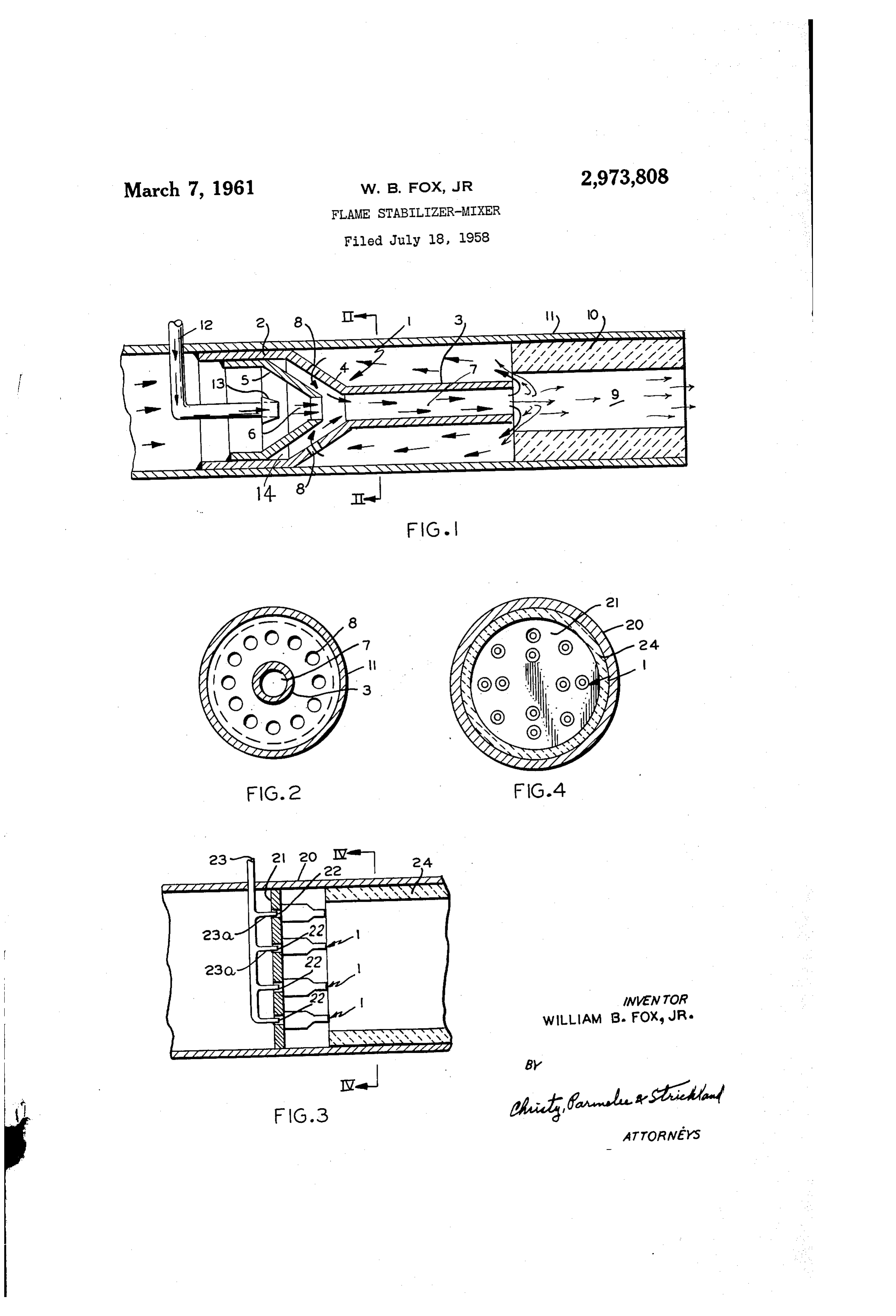
2,973,808 Fig. 4 shows a full cross-section taken on line IV-IV of Fig. 3.
FLAME STABLIZER-MIXER Referring now in detail to Fig. 1 of the drawing, the William B. Fox, Jr., Carnegie, Pa. flame stabilizer-mixer comprises an annular member 1 (3692 Elmira Drive, Dayton 39, Ohio) 5 diametera hollow having hollow cylindrical portion 2 and a reduced cylindrical extended portion 3 which are
Filed July 18, 1958, Ser. No. 749,426 connected by a converging portion 4. Within portion 2 is a Second converging member 5 disposed in spaced re lation to portion 4 of member 1. The diameter of the
The present invention is concerned broadly with com- 0 opening 6 therein is preferably not greater than the diameter of the opening 7 in member 1. Within con bustion of fuels and high conversion and throughput in chemical reactors. Specifically, the invention is con verging purpose portion 4 are a plurality of perforations 8 for a to be hereinafter described. The small end por cerned with a novel form of mixer for fluids or solids before entering a combustion zone and imparting mixing tion 3 of member 1 terminates in a combustion zone 9. Members 1 and 4 may advantageously be of metal and action to such fluids or solids within a combustion zone 5 the combustion zone should have an internal refractory of a fuel burner or a reaction zone of a chemical reactor.
It is well known that in the usual combustion pro suitable lining 10. The members 1 and 10 may be housed in any cesses the mixture of fuel and air entering the com form of housing such as the cylindrical member bustion zone are seldom at an optimum and the required it. Obviously, the member 11 may be of other forms to further mixing therein within the combustion zone is even 20 Suit the particular installation where the flame stabilizer mixer may be used. The liner 10 has an internal diameter less efficient. In most any commercial or industrial larger than the internal diameter of portion 3 of mem process minimum size of apparatus is desirable both ber 1 for a purpose to be discussed. The fuel to be com from the standpoint of space and economy. Exothermic busted is introduced into the member 5 by any suitable reactions such as result in combustion of fuels suggests means such as the tube 12 and nozzle 13. The combus obtaining higher heat release by increased volumes of 25 tion air may be also introduced into member 5 by any fuel combusted or increased heat release per unit of com Suitable means, and where atmospheric pressure air is bustion volume. In the present invention a higher heat used it may be introduced into member 11, upstream of release per unit of volume of combustible fuel is ob tained by improved mixing of the fuel-air components of theDuring tube 12 or in any other suitable manner. operation of the stabilizer-mixer of Fig. 1, the combustion. 30 air and fuel entering member 5 is initially mixed and When the volume of the fuel-air mixture combusted mixing continues during passage through portion 3 of in a given unit of time is increased the problem of flame member 1 and enters the combustion zone 9 where the blowout is troublesome. Such problems increase where mixture is ignited by any suitable means (not shown). a minimum size of equipment is desirable such as in aerodynamic applications, compact reaction designs and 35 The primary air and fuel moving through member 1 cre mixing in small volumes. In the present invention the 5ates and a suction in the chamber 14 formed by the member member 1. The suction acting through perforations mixer also acts as a flame stabilizer particularly when 8 withdraws products of combustion from within the operated at atmospheric pressure, and gives improved the combustion chamber 9 into the member 1 where they results at less than atmopheric as well as greater than mix with the primary fuel and again pass into the com atmospheric pressures. 40 bustion chamber. Such action creates an additional turbu
Pre-heating of fuels is often resorted to in order to lence in the combustion which in turn restricts fiame increase the combustion efficiency of air-fuel mixtures. blowout. This cycle is continued during operation of In the present invention the manner of mixing the fuel air components has eliminated the necessity for pre theThe burner.
heating to obtain high heat release from selected fuels. 45 release advantage of such a burner lies in the high heat obtained per volume unit of combustion zone
Tests have demonstrated that with the burner of the volume at atmospheric pressures. Hence, by reason of invention using non-preheated propane-air stoichio the unique mixing obtained by such a burner, very large metric mixtures, heat releases on the order of 60 million heat release can be obtained with a minimum size of B.t.u. per hour per cubic foot of combustion zone volume combustion zone at atmospheric pressure. Likewise were obtained without flame blowout, when operated at 50 when used in chemical reactors a high rate of conversion atmospheric pressure. with high throughput of reactants is obtainable for a One object of the invention is to provide a combustion burner for improved mixing of fuels before and after given The reactor volume.
exact nature of the mixing operation is not com entering the combustion zone. pletely understood, it appears, however, that the enter Another object of the invention is to provide a new and 55 ing primary fluids, air and combustible fuel, entrain improved mixer giving a high rate of conversion with burner gases from the reaction zone and mix them inti high output in chemical reactors. mately with the entering primary fuel within a relatively A further object of the invention is to provide a mixer low pressure zone before discharging into the combustion burner of the character described which is operable at zone. Such reverse circulation from the combustion atmospheric pressures in obtaining high heat release per 60 Zone results in a high throughput and combustion in a unit of combustion zone volume when using gases, relatively small combustion zone. liquids, fine solids or any combinations thereof. A modification of the invention as disclosed in Fig. 3, These and other objects of the invention will be made utilizes a large size tube or housing 20 within which is apparent from the following description and the draw mounted a transversely disposed plate 21 having a plu ings forming a part thereof, wherein: . 65 rality of suitably arranged rows of openings 22 therein. Fig. 1 shows a longitudinal section through one form of a burner of the invention; The connection between plate 21 and tube 20 being gas Fig. 2 shows a full section taken on lines II-II of tight. having
Over each opening 22 is arranged a member 1 the converging member 5 therein as disclosed in
Fig. 1; Fig. 1. A suitable combustible fuel inlet conduit 23 Fig. 3 shows another form of burner of the invention 70 extends into housing 20 and is provided with branch in which a plurality of stabilizer-mixers are mounted upon inlet tubes 23a which are smaller in diameter than open a perforated plate within a tube;
Page 3scan →
ings 22 in plate 21 and are entered into each member 1 housing upstream of said first named member and de as in Fig. 1. Upstream of plate 21 a suitable connec livering fuel within said second named member converg tion to housing 20 provides inlet air for combustion ing portion, and an air intake in said housing upstream purposes. The air-fuel mixtures issuing from members of said members.
are ignited and the operation is carried out as pre-- 2. In a burner, in combination, an open housing pro viously described in regard to Fig. 1. A refractory viding at one end an inlet for air and combustible fuel lining 24 is provided in the combustion chamber portion and at the other end an inwardly extending combustion of housing 20. zone, a flame stabilizer and fuel mixer extending inwardly The relative sizes and shapes of the stabilizer-mixers disclosed and described may be varied to suit any par ingthea hollow of housing from said combustion zone and compris cylindrical member disposed in annular ticular installation. Optimum results have been obtained spaced relation to the adjacent housing portion and ad with atmospheric pressures when the following basic jecent the combustion zone, a diverging frusto-conical design relations are maintained. The member 1 should member forming an upstream continuation of said cylin be connected with the housing or other support so that drical member and extending therefrom to engagement no by-pass of gases or fluids at the point of connection with the housing to form a gas tight seal therewith, a occurs. The opening 6 in member 5 should be no larger second hollow frusto-conical member within said hous than opening 7 in member 1. The length of portion 3 ing in upstream spaced parallel relation to and extending of member 1 is preferably 3 to 8 times the internal diam into the first named frusto-conical member forming a eter thereof. The openings 8 in member should be suction chamber between them, the small end opening adjacent or upstream of opening 5a in member 5, pref in said second frusto-conical member being in axial align erably never downstream relative to said opening. The ment with the opening through said hollow cylindrical primary fluid is adequately mixed by introducing one member and of an inside diameter not greater than that fluid or fluid mixture into the upstream opening of mem of said cylindrical member, apertures arranged in radially ber i and preferably slightly downstream from said spaced relation about the periphery of the first named opening. The other primary fluid may be introduced at 25 frusto-conical member in upstream relation to the small some point upstream for flow into the member 1. Where end of the second said frusto-conical member, means exothermic reactions are involved, as in a combustion for introducing combustible fuel through said burner burner, the combustion zone should be insulated with housing into said second named frusto-conical member an internal refractory lining. and an inlet on said housing upstream of said mixer for en using atmospheric pressures, adequate suction 30 introduction of combustion air, through apertures 8 of portion 4 of member 3 are ob 3. In a burner, in combination, a hollow tubular hous tained when the end of member 5 is spaced from the ing, a plate disposed transversely of said housing, in adjacent end of portion 3 of member 1, a distance about wardly from one end thereof blocking off flow of air equal to the diameter of the opening 7 in said portion 3. through the housing, a plurality of spaced openings ex The length of said portion 3 provides adequate mixing tending through said plate in a direction axially of the of the primary fuels during passage therethrough. The housing, a fuel mixer associated with each plate open mixed fuels entering the combustion zone have little or ing and comprising a hollow tubular member secured to no turbulence at atmospheric pressures, and the volume the downstream side of said plate enclosing said opening, throughput of mixed fuels tends to cause flame blow out an axially extending forwardly converging hollow exten in the well known manner. Where, however, the inter 40 sion on said tubular member and terminating in an axially nal diameter of the combustion zone exceeds the external extending hollow tubular extension, a downstream ex diameter of the portion 3 of member 1 some of the tending hollow member disposed within said fuel mixer products of combustion within the combustion zone, hollow tubular member and having a converging portion adjacent the end of member 1 are withdrawn upstream extending into and in parallel spaced relation with said over Said portion 3 and enter the stream of primary fuel mixer converging extension and terminating short of through opening 8 of the member 1. This recirculation, said mixer hollow tubular extension, a plurality of aper i.e.; reverse flow, at the ignition end of the combustion tures in said mixer converging extension, a fuel supply burner creates a turbulence within the combustion zone tube extending through said housing upstream of said and restricts flame blow out. Where design requirements plate, a conduit extending from said fuel supply tube dictate a constriction of the outer end of the combustion : through each said plate opening in spaced relation to the Zone increased pressures upstream of the combustion periphery thereof, and an air inlet opening in said hous ZOile are necessary to obtain the desired turbulence.
i claim
ing upstream of said plate.
1. A burner comprising a tubular housing, a tubular ing,4. a Infuela flame stabilizer burrier, in combination, a hous receiving member mounted in gas-tight relation ember disposed within said housing having a cylindrical 55 to the inner face of the housing and having a downstream portion in gas tight contact with the inner walls of the converging portion terminating in a mixing chamber ex housing and secured thereto, a downstream extending tending axially of the housing in inwardly spaced rela converging continuation of said cylindrical portion dis tion thereto forming a recirculation chamber, a corn posed in Spaced relation to said housing and terminating bustion chamber in said housing extending downstream in an elongated cylindrical extension in spaced relation from Said mixing chamber in radially spaced relation to the adjacent portion of the housing, said elongated thereto, a second converging member disposed within cylindrical extension terminating in inward spaced rela Said fuel receiving member and having a converging por. tion to the downstream end of the housing providing a tion in Spaced relation with and extending into the con combustion chamber within the housing, a second tubular verging portion of said fuel receiving member forming member mounted upon the inner walls of the cylindrical a suction chamber, and apertures in said fuel receiving portion of the first named member, a downstream extend member converging portion connecting said burner suc ing converging continuation of said second tubular mem tion chamber with the combustion chamber through said ber extending into and spaced from the converging con recirculation chamber.
tinuation of the first named member and terminating upstream from the Said elongated cylindrical extension 70 References Cited in the file of this patent of the first member, a plurality of radially disposed per forations in the converging portion of said first named UNITED STATES PATENTS member disposed in upstream relation to the downstream 2,547,276 Marsh et al. ------------- Apr. 3, 195 end of the converging portion of the second named mem-. 2,701,608. , Johnson ---------------- Feb. 8, 1955 ber, a fuel nozzle extending inwardly...of said tubular. 75 2,857,961 Brown et al. 2.----------- Oct. 28, 1958;
Provenance
- Collection
- Patents citing this work
- Pages
- 3
- Method
- pdftotext (the PDF's own text layer) + pdftoppm 300dpi page scans
- Patent office record
- patents.google.com →
- Source
- Google Patents citing-documents table
- Assignee
- Jr William B Fox
- Published
- 1961-03-07
- Transcribed from
- patentimages.storage.googleapis.com →