

patent · US3038530A
Flame thrower
12 June 1962
Text
Drawings
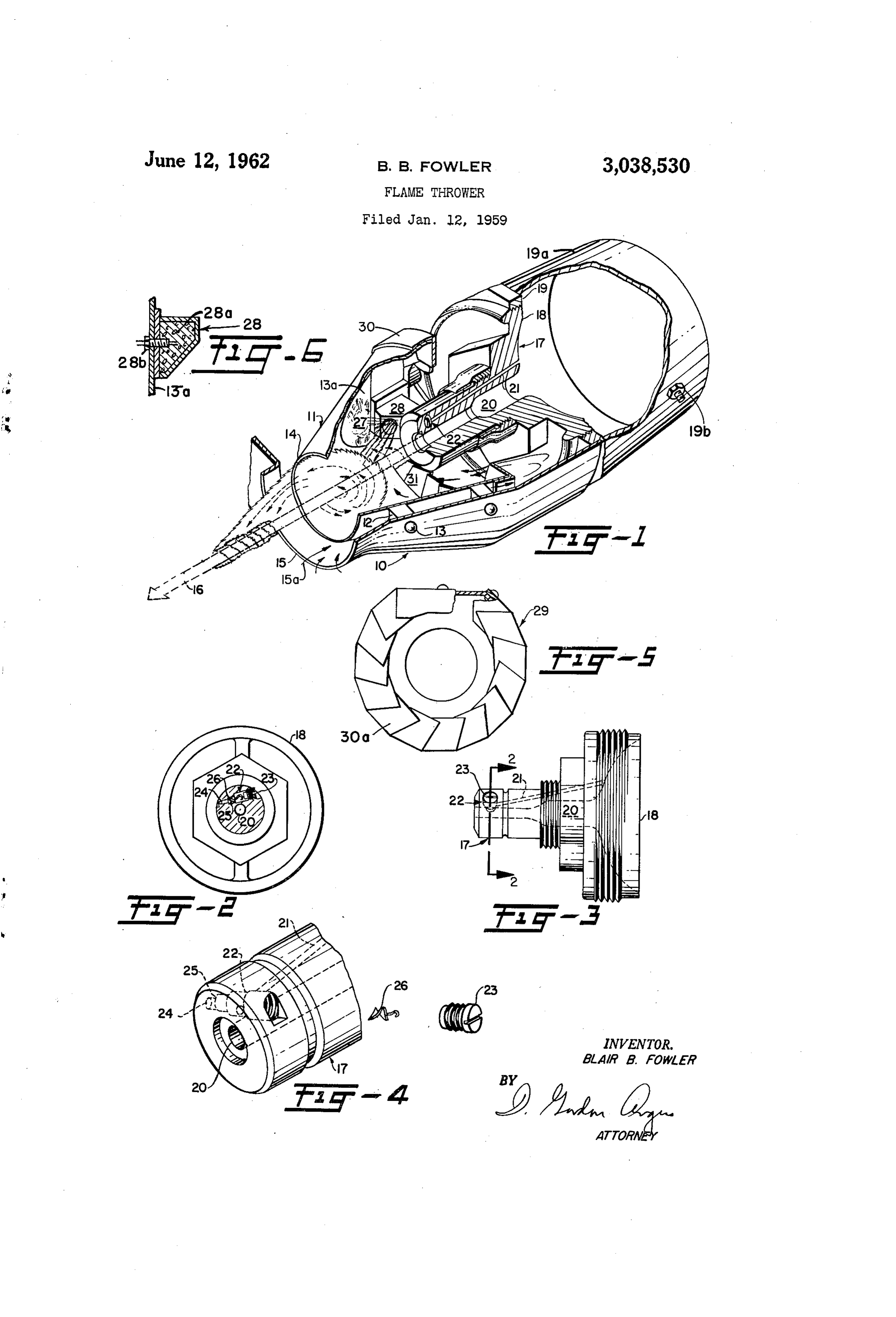
FIG. 2 is a detail view in front elevation partly in 3,038,530 section of the nozzle of the flame thrower and tank closure FLAME THROWER on which it is mounted, the nozzle being sectioned on Blair B. Fowler, Monrovia, Calif., assignor to Aerojet the line 2-2 in FIG. 3.
Page 1drawing sheetscan →
Page 2scan →
United States Patent Office Patented June 12, 1962
FIG. 2 is a detail view in front elevation partly in 3,038,530 section of the nozzle of the flame thrower and tank closure FLAME THROWER on which it is mounted, the nozzle being sectioned on Blair B. Fowler, Monrovia, Calif., assignor to Aerojet the line 2-2 in FIG. 3.
general Corporation, Azusa, Calif., a corporation of 5 FIG. 3 is a side elevation of the parts shown in FIG. 2. Ohio
Filed Jan. 12, 1959, Ser. No. 786,348 FIG. 4 is a fragmentary perspective view, drawn on 14 Claims. (CI. 158-28) a larger scale, of the delivery end of the nozzle, showing parts normally mounted therein withdrawn therefrom.
The present invention relates to means for igniting a FIG. 5 is a front view drawn on a larger scale of an stream of fuel and particularly to the ignition of fuel O air directing member arranged in a chamber surrounding projected under pressure from a nozzle as a rod-like the nozzle.
stream, as in flame throwers. FIG. 6 is a cross-sectional view of the igniter elle In a flame thrower it is an important requirement that ment.
adequate range be obtained and one consideration to be Referring to FIG. 1, the numeral 10 indicates a por met is that the fuel stream should leave the nozzle with 5 tion of the shroud covering the operative parts of the minimum interference in order that the kinetic energy of flame thrower. The subject flame thrower is operable the liquid stream be conserved as much as possible while on either liquid or thickened (jelled) fuels which are at the same time the stream should ordinarily reach its commonly used in flame thrower applications. The fuel target aflame so that complete combustion of the fuel under pressure exits the nozzle in similar form with shot from the flame thrower results on the restricted 20 either liquid or jelled fuel, that is, a rod-like stream of target area fired at. Of equal importance is the fact that fuel. The liquid fuel disperses rapidly after being emit the range attainable with a fuel stream is doubled or even ted and ignited from the nozzle into a billowy flame tripled when properly ignited. front while the thickened or jelled fuel can be used for It is an object of the invention to provide ignition long range flame throwing purposes wherein the time for means for a flame thrower by which means the nozzle is 25 ignition of the jelled fuel is greater in respect to the liquid Surrounded by a body of flame whirling about the axis fuel and the flame front is substantially restrictive. Jelled of the jet of fuel so that the surface of the jet is ignited fuels generally allow a longer maximum range for the without interference with the main body of the jet. flame thrower while liquid fuels can cover a greater It is a further object of the invention to utilize the fuel area at a much shorter relative range. The prob in the flame thrower for ignition of the stream of fuel 30 lem, of course, is the matter of ignition of a liquid ver by providing a fuel bleed directing a small jet of fuel sus a jelled fuel. Partial ignition of any fuel reduces in the form of a spray into a chamber or flame cone efficiency, therefore, a greater amount of attention is Surrounding the nozzle and igniting said spray by means directed to the method of ignition.
Serving also to ignite a propellant grain or charge, the A conical flame cone is mounted within the shroud burning of which serves to pressurize the fuel in the 35 0 and is spaced from the wall thereof by spacing blocks flame thrower tank, burning of the sprayed fuel after 12 and rivets 13. The flame cone 1i projects for a con initial ignition being self-supporting. siderable distance beyond the delivery end of the nozzle. It is another object of the invention to provide an ig The flame cone 11 is flattened in the area 3a on its in niting device having a chamber surrounding the nozzle ward side and its open end 14 is spaced peripherally from and an orifice through which the ignited stream of fuel 40 the edge 15 of an opening in the shroud 10 through which from the flame thrower is ejected, said orifice being sur the concentrated stream of fuel, or fuel rod, 16 is ejected. rounded by the intake of a casing surrounding the cham The nozzle 17 from which the fuel rod is ejected un ber having orifices connecting the casing to the chamber der high pressure is located axially in the flame cone 11, behind the opening of the nozzle so that the envelope of and is carried by a closure 18 screwed into the head air entrained by the jet causes a reduced pressure to be set 45 casting 19 of the flame thrower to which the pressurized up in the casing resulting in a rush of air at atmospheric source of fuel 19a is attached. A ball check valve 19b, pressure to enter said casing and supply the air required attached to the source of fuel 19a, may be used to ad to maintain the body of flame surrounding the nozzl mit pressurized air or the like, the closure 18 closing after the spray of fuel has been ignited. the delivery end of the tank. With the above and other objects in view, which will 50 The main fuel passage 20 in the nozzle is stepped appear from the following specification and accompany down in diameter toward the end of the nozzle ending ing illustrative drawings, the invention comprises a fuel in length of bore of relatively small diameter. nozzle provided with a conduit from which a secondary A passage 21 for a secondary flow of fuel is drilled spray of fuel is projected into a chamber surrounding the from the inner surface of closure 18 longitudinally nozzle, said chamber having an open end positioned 55 through the wall of the nozzle and connects with a trans ahead of the nozzle for the passage of a compact stream verse passage 22 drilled through the wall of the nozzle of fuel ejected through said nozzle, means to ignite said adjacent its outer end. The arrangement of the pas Secondary spray, and a casing surrounding said chamber Sages is clearly shown in FIGS. 2, 3 and 4. One end and having a wall spaced from the wall of said chamber of passage 22 is closed by the threaded plug 23 and the and around the open end of said chamber for the entry 60 opposite end 24 is reduced in diameter providing a pe of atmospheric air around the open end of the chamber ripheral shoulder 25. The reduced end 24 is positioned and into the space between the walls of said chamber opposite the flattened portion 27 so that the secondary and casing, said chamber and casing being in communi Supply of fuel is dispersed or splashed causing it to en cation behind the forward end of the nozzle whereby air velop the entire fuel rod. A spinner 26 is mounted in is supplied to maintain the flame of said secondary spray 65 the passage 22 abutting shoulder 25, the function of the around the nozzle to cause ignition of the surface of spinner being to cause the secondary fuel to issue as a said compact stream of fuel issuing from said nozzle. whirling spray, striking the flattened area of the flame In the drawings: cone as indicated at 27, from the reduced end 24 of pas FIG. 1 is a fragmentary perspective and sectional view sage 22.
of the nozzle of a flame thrower, the section being taken 70 The igniter element 28, best shown in FIGS. 1 and partly vertical to the axial line of the nozzle and partly 6, has a pyrotechnic charge 28a therein. A squib or horizontal to said axis. glow plug 28b is inserted in the charge 28a for ignition 3 purposes. The direction in which the flame of the ig entering through the overlapped blades 30a. The fuel inition charge is directed into the flame cone is chosen is forced through the nozzle 20 in a rod-like form, 16, so as not to disrupt the fuel-rod, the flame of the igni- and has a swirling flame front enveloping it completely tion charge travelling in the: same - direction as the fuel 5 stream · rod.
to propagate the ignition of the entire main rod-like of fuel. The purpose of the swirling action is to
The air flow required to maintain burning of the sec completely surround the rod-like stream of fuel and pre ondary fuel is caused by the reduced air pressure set up vent mere partial ignition of the main stream of fuel. in the flame cone by the injector action of the fuel-rod, Ignition devices whichenhance do not completely envelop the being ejected therethrough at high speed. Air from out main stream of fuel the the possibility of partial efficiency of the entire flame side the front end of the flame thrower flows through 10 throwing ignition and reduce the gap 15a, between the shroud. i0 and flame cone 11 A preferred embodiment of the invention has been and over the outside of the flame cone, 11 into the space: ; ; ;
behind the air-directing and flame-holding member 29. specifically, described and shown in the accompanying The air enters it behind the end of the nozzle as indi- drawings by way of illustration, but not as limitative of SkLmLL LLLL LLL LGGLLLLLLL LL LLLLLLLLSS0SSSSSSSSSSSSSSSS 00 LL LLLLLL L L L LlL L L L LLLLLlLLLLLLL LLLLLLLlLLLlLLLLLLL LL LLLLL S LLLL S In order to give the air awhirling motion and aid in in the described enbodiment by those skilled in the art preventing the flame from spreading back from the flame without departing from the scope of the invention as ' icone, the flame holder member 29 is mounted on the defined by the appended claims. back of the flame cone 11 and extends radially inwardly 20 11.I claim: ,,,,,, toward the nozzle. . . . . . . . . . . . . . . . . . . . . . . . . . ing a concentratedthrower,
In a flame.
stream means for igniting and project of pressurized fuel comprising:
The member 29 as shown in FIG.5 comprises a sheet i metal, ring 30 cut parti way through from o le; edge at a arelation source of pressurized fuel; a fuel nozzle in supplying to said pressurizing fuel and adapted to project a :plurality -. of poi ts, the cut portions being bent at right angles to the ring and twisted to form overlapping blades 25 rounding od-like stream of fuel; a flame containing housing sur 30a. The ring of metal is flattened on one side to lie thereof; means said nozzle and projecting beyond the end over and against the flattened portion 13a of the flame into said housingforat projecting a secondary supply of fuel an angle to the axis of the fuel nozzle; ; ; ; ; ;
means to disperse said secondary supply of fuel to com ; pletely surround said rod-like stream of fuel; means for nites the propellant grain pressurizing the tank of 30 initiating ignition of said secondary pply of fuel to pro flame thrower simultaneously with the ignition of the duce flame within said housing surrounding the rod-like secondary fuel injected into the flame cone, the igniter surface stream of fuel adjacent its exit from the nozzle to effect for the secondary jet may be fired by electrical glow ignition of said rod-like stream of fuel; and plug means and may be provided as a separate igniter means providing for the flow of air into said housing to from
: : : : for the -propellant tankipressurizing - - - device, the : 35 maintain the combustion of said secondary fuel. . . . . . .
: separate igniters being controlled by one trigger thus: 2. In a flame thrower, means for igniting and proj enabling a straight tank to be used, or a tank containing ing a concentrated stream of pressurized fuel comprising: fuel put under pressure by a compressed gas might be : a source of pressurized fuel; a fuel nozzle in supplying used, the trigger operated igniter serving only to ignite. relation to said pressurized fuel and adapted to project : the secondary fuel jet in the flame cone. 40 rod-like stream of fuel; a flame-containing conical housing The flame in the flame cone is maintained in a swirl surrounding said nozzle and having an opening at the ing path in contact with the fuel rod issuing from the narrower end thereof positioned to surround the rod-like nozzle and remains in contact with the surface of the stream of fuel at a point spaced beyond the exit of the rod for a distance sufficient to ignite the surface of the fuel from the nozzle and the wider end of the housing sur fuel rod which travels through the air burning only on 45 rounding said nozzle; means projecting a secondary Sup its outer surface to a point at which the decreasing speed ply of fuel into said housing; means to disperse said of the fuel rod end due to air resistance and vaporizing secondary supply of fuel to completely surround said rod of the fuel toward the end of the fuel rod due to its con like stream of fuel; means for initiating ignition of the dis tinued surface burning causes scattering of the end into persed secondary supply of fuel to produce flame within droplets resulting in dropping of the fuel rod end unless bu said housing surrounding the rod-like stream of fuel ad the fuel stream impinges against a target. On impinge jacent its exit from the nozzle to effect surface ignition of ment, the burning stream splatters and envelops the tar said rod-like stream of fuel; and means providing for the get in flame. flow of air into said housing to maintain the combustion Operation of said secondary fuel.
Initially all openings in the shroud nozzle and igniter 55 3. In a flame thrower, means for igniting and projecting are closed by means such as plugs or discs which are a concentrated stream of pressurized fuel comprising: a blown out of place when the trigger of the flame throw source of pressurized fuel; a fuel nozzle in supplying re er is operated to cause ignition of the gas generator. lation to said pressurized fuel and adapted to project a Pressure is thereafter immediately applied to the tank, rod-like stream of fuel; a flame-containing conical housing forcing a concentrated stream of fuel or "fuel rod' 60 to having an opening at the narrower end thereof positioned surround the rod-like stream of fuel at a point spaced through the nozzle and flame cone and projecting it from beyond the exit of the fuel from the nozzle and the the flame thrower. The secondary stream of fuel is wider end of the housing surrounding said nozzle; an emitted from the reduced end 24 after it is dispersed or annular member projecting inwardly from said wider broken by the whirling spinner 26 and still being under end of the housing and formed to provide blades causing the pressure of the source from which it was received, it whirling of air entering the wider end of the housing; is forced against the flattened portion 13a. The dis means projecting a secondary supply of fuel into said persed secondary supply of fuel splashes or disperses housing; means to disperse said secondary Supply of fuel within the flame-containing housing to surround the rod to completely surround said rod-like stream of fuel; means like stream of fuel and simultaneously is ignited by the 70 for initiating ignition of the dispersed secondary supply charge emitted by the igniter element 28. This envelope of fuel to produce flame within said housing surrounding of flame composed of ignited particles of the secondary fuel tend to be swirled by the swirling action of the in to effect surface ignition ofadjacent the rod-like stream of fuel said its exit from the nozzle rod-like stream of fuel;
clined direction of the restricted orrifice 24 striking the 75 and means providing for the flow of air into said housing flattened portion 13a plus the Swirling action of the air 4 through said blades to maintain the combustion of said rod-like stream of fuel adjacent and after its exit from the secondary fuel. nozzle; and means providing a flow of air into said hous 4. In a flame thrower, means for igniting and project ing to maintain the combustion of said spray of fuel. ing a concentrated stream of pressurized fuel, comprising: 7. In a flame thrower, means for igniting and projecting a source of pressurized fuel; a fuel nozzle in supplying a concentrated stream of fuel as set forth in claim 6 and relation to said pressurized fuel and adapted to project a in which said latter passage is arranged to direct the rod-like stream of fuel; a shroud enclosing said nozzle whirling spray of secondary fuel against the inner surface and provided with an opening through which an ignited of said housing.
stream of fuel is projected; a conical flame containing 8. In a flame thrower, means for igniting and project housing surrounding said nozzle and projecting beyond 0 ing a concentrated stream of pressurized fuel comprising: the end thereof having an opening at the narrower end a source of pressurized fuel; a fuel nozzle in supplying thereof positioned within but spaced from the perimeter relation to said pressurized fuel and adapted to project of the opening in the shroud affording an opening for the a rod-like stream of fuel; a flame containing housing sur free passage of air between said shroud and said housing rounding said nozzle and projecting beyond the end there and positioned to surround the rod-like stream of fuel at of; means for providing a flow of air into said housing a point spaced beyond the exit of the fuel from the nozzle to maintain the combustion of said spray of fuel; means and the wider end of the housing surrounding said nozzle; projecting a secondary supply of fuel into said housing; an annular member mounted on the wider end of said a flattened portion of said flame-containing housing being : housing and projecting inwardly therefrom and formed aligned with said projecting means for said secondary to provide blades causing whirling of air entering the 20 supply fuel whereby said secondary supply of fuel is dis space between the perimeter of the opening in the shroud persed in said flame-containing housing completely sur and the outer surface of said housing and entering the rounding said rod-like stream of fuel; and an ignition wider end of the housing; means projecting a secondary member adapted to direct a flame into said housing to supply of fuel into said housing; means to disperse said initially ignite the secondary fuel in said housing. secondary supply of fuel to completely surround said rod 25 9. In a flame thrower, means for igniting and project like stream of fuel; means for initiating ignition of the ing a concentrated stream of fuel comprising: a source dispersed secondary supply of fuel to produce flame of pressurized fuel; a fuel nozzle in supplying relation to within said housing surrounding the rod-like stream of said pressurized fuel and adapted to project a rod-like fuel adjacent its exit from the nozzle to effect surface ig stream of fuel; a flame containing housing open at each nition of said rod-like stream of fuel; the combustion of 30 end and surrounding said nozzle and projecting at its said secondary fuel being maintained by the air entering forward end beyond the forward end of said nozzle; the wider end of the flame housing. means projecting a secondary supply of fuel into said 5. In a flame thrower, means for igniting and project housing; a flattened portion on said flame-containing hous ing a concentrated stream of pressurized fuel, comprising: ing being aligned with said projecting means for said a source of pressurized fuel; a fuel nozzle in supplying re 35 secondary supply of fuel whereby said secondary supply lation to said pressurized fuel and adapted to project a of fuel is dispersed in said flame-containing housing com rod-like stream of fuel; a conical flame containing hous pletely surrounding said rod-like stream of fuel; and an ing surrounding said nozzle and having an opening at the ignition member arranged to direct a flame into said hous narrower end thereof positioned to surround the rod-like stream of fuel at a point spaced beyond the exit of the 40 ing in a direction to ignite said secondary fuel but to prevent disruption of said rod-like stream of fuel and fuel from the nozzle and the wider end of the housing means providing a flow of air into said housing to main surrounding said nozzle behind the forward end of the tain the combustion of said spray of secondary fuel. nozzle; said nozzle having a passage through the wall of 10. In a flame thrower, means for igniting and project said nozzle diverting a portion of the pressurized fuel sup plied to said nozzle and delivering said diverted fuel as a 45. pressurized fuel;stream ing a rod-like of fuel, comprising: a source of a fuel nozzle in supplying relation to spray into said housing; means to disperse said portion of said pressurized fuel and adapted to project said rod-like pressurized fuel to completely surround said rod-like stream of fuel; a conical open ended flame containing stream of fuel; means for initially igniting the dispersed housing surrounding said nozzle with its narrower end spray of fuel to produce flame in said housing surround projecting beyond the forward end of the nozzle; said ing the rod-like stream of fuel adjacent and after its exit 50 nozzle having a passage inclined at an angle to the direc from the nozzle; and means providing for the flow of air tion of said rod-like stream of fuel and delivering a spray into said housing to maintain the combustion of said of secondary fuel into said housing; a flattened portion spray of fuel. of said flame-containing housing being aligned with said 6. In a flame thrower, means for igniting and project secondary fuel positioned substantially parallel to said ing a concentrated stream of pressurized fuel, comprising: 5 5 rod-like stream of fuel; an ignition means arranged to a source of pressurized jelled fuel; a fuel nozzle in supply direct a flame for combustion of said spray within said ing relation to said pressurized jelled fuel and adapted housing in a direction preventing disruption of said rod to project a rod-like stream of fuel; a conical flame con like stream of fuel; and means providing a flow of air taining housing surrounding said nozzle and having an into said housing to maintain the combustion of said opening at the narrower end thereof positioned to sur 60 spray of secondary fuel.
round the rod-like stream of fuel at a point spaced beyond 11. Means for igniting and projecting a rod-like stream the exit of the fuel from the nozzle and the wider end of the housing surrounding said nozzle behind the forward of fuel, as set forth in claim 10 and in addition compris end of the nozzle; said nozzle having a passage extending ing: means to establish a flow of air from outside the axially through the nozzle and communicating with said 65 forward end of said coneshaped housing and guiding it source of pressurized fuel; the wall of said nozzle having into the back of the housing with a whirling motion. a passage therethrough and communicating with said 12. In a flame thrower, means for igniting and project source of pressurized fuel, and spinner means located ing a concentrated stream of pressurized fuel comprising: in said latter passage whereby the fuel flowing through a source of pressurized fuel; a fuel nozzle in supplying said passage is delivered as a whirling spray into 70 relation to said pressurized fuel and adapted to project said flame housing; means to disperse said source of pres a rod-like stream of fuel; a flame containing housing sur surized fuel flowing through the passage in the said wall rounding said nozzle and projecting beyond the end of said nozzle to completely surround said rod-like stream thereof; means for projecting a secondary supply of fuel of fuel; means for initially igniting the dispersed spray into said housing at an angle to the axis of said nozzle; of fuel to produce flame in said housing surrounding the 75 a splash plate contained by said flame-containing housing 5 being aligned with said projecting means for said second said nozzles second passage terminating in an orifice airy supply of fuel and having a position substantially projected at an angle to the direction of said rod-like parallel to said rod-like stream of fuel whereby said stream of fuel, a splash plate received by said housing secondary supply of fuel will envelop said rod-like stream aligned with said nozzle orifice and positioned to deflect of fuel; means for initiating ignition of said secondary said secondary supply of fuel in a swirling motion around supply of fuel to produce flame within said housing and said rod-like supply of fuel, and means to ignite said surrounding the rod-like stream of fuel adjacent its exit secondary supply of fuel.
from the nozzle to effect surface ignition of said rod-like 14. In the flame thrower as set forth in claim 13 in stream of fuel; and means providing for the flow of air O which blades said air flow introducing means is a plurality of in said housing.
into said housing to maintain the combustion of said secondary fuel. n 13. A flame thrower comprising: a pressurized fuel References Cited in the file of this patent source, a fuel nozzle in supplying relation to said fuel UNITED STATES PATENTS source, said nozzle having a main passage adapted to pro 1,304,710 Seidler ––-------------- May 27, 1919 ject a rod-like stream of fuel, a conically-shaped housing 5 surrounding said nozzle and having its axis substantially 1,797,654 Grund –--------------- Mar. 24, 1931 concentric with said rod-like stream of fuel and having 2,480,147 Letvin ---------------- Aug. 30, 1949 a passageway for said stream of fuel positioned with its 2,497,939 Garraway et al. -------- Feb. 21, 1950 diverging portion forward of said nozzle, a means for 20 2,574,495 introducing a flow of air adjacent to said rod-like stream 2,701,608 Johnson --------------- Feb. 8, 1955 of fuel and having a swirling motion, said nozzle having 2,857,961 Brown III et al. -------- Oct. 28, 1958. a second passage adapted to project a secondary supply of fuel and in supplying relation with said fuel source,
Provenance
- Collection
- Patents citing this work
- Pages
- 5
- Method
- pdftotext (the PDF's own text layer) + pdftoppm 300dpi page scans
- Patent office record
- patents.google.com →
- Source
- Google Patents citing-documents table
- Assignee
- Aerojet General Co
- Published
- 1962-06-12
- Transcribed from
- patentimages.storage.googleapis.com →