

patent · US3051226A
Recirculating combustion apparatus
28 August 1962
Text
Drawings
Page 1drawing sheetscan →
Page 2drawing sheetscan →
Page 3scan →
United States Patent Office 3,051,226 Patiented Aug. 28, 1962 tion of the fire pot will vary with the furnace and the 3,051,226 fire pot may be, for example, circular, rectangular, Square RECRCULATING COMBUSTION APPARATUS or hexagonal in shape. Port 5 is provided in the furnace Bruce R. Walsh, Pittsburgh, Pa., assignor to Gulf Re for receiving the burner 6. The burner 6 can be any search & Development Company, Pittsburgh, Pa., a of the burners commonly used in the art for supplying a corporation of Delaware combustible mixture of a liquid or gaseous fuel and air to Filed Aug. 5, 1958, Ser. No. 753,254 the combustion chamber. One such burner is the gun type burner which is utilized to supply a mixture of liquid
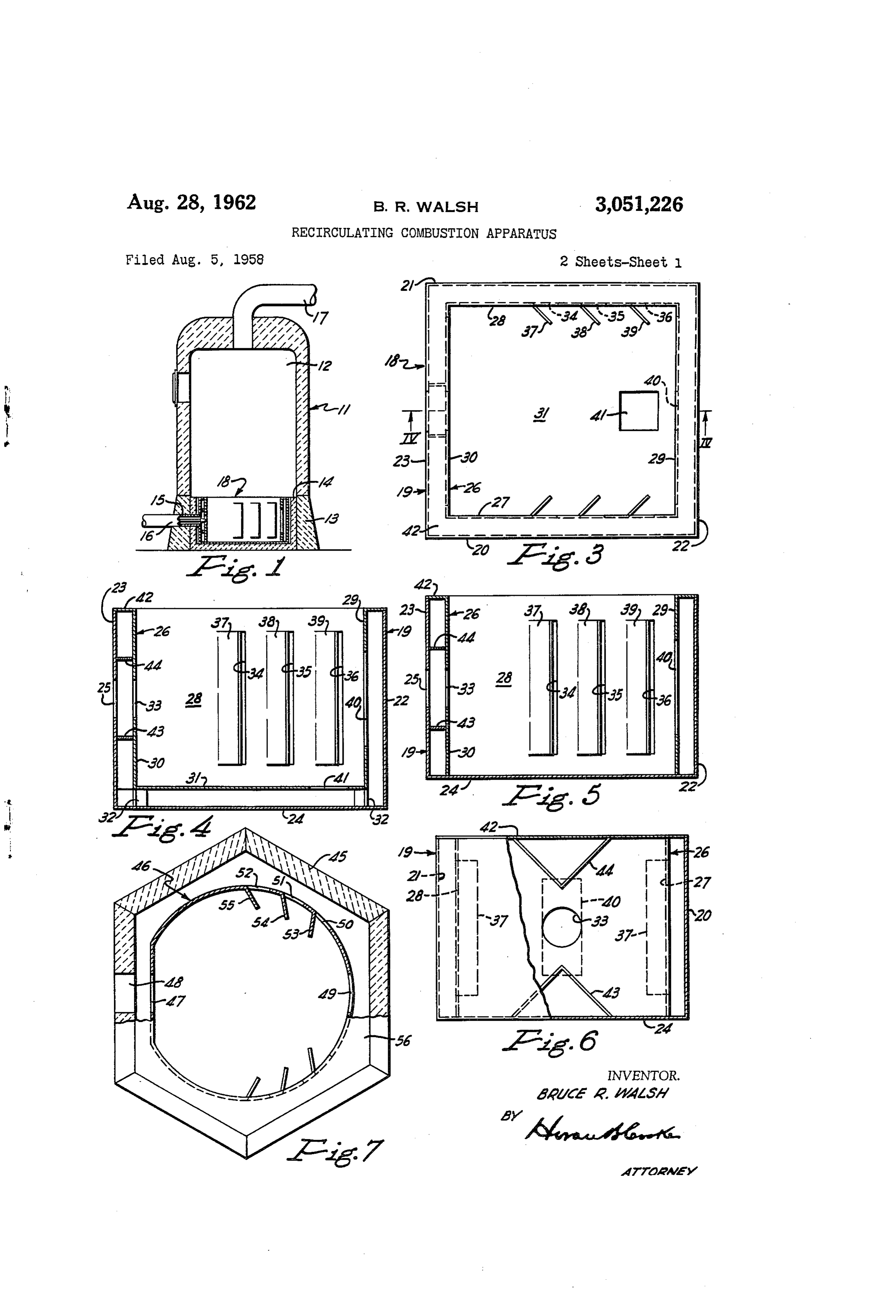
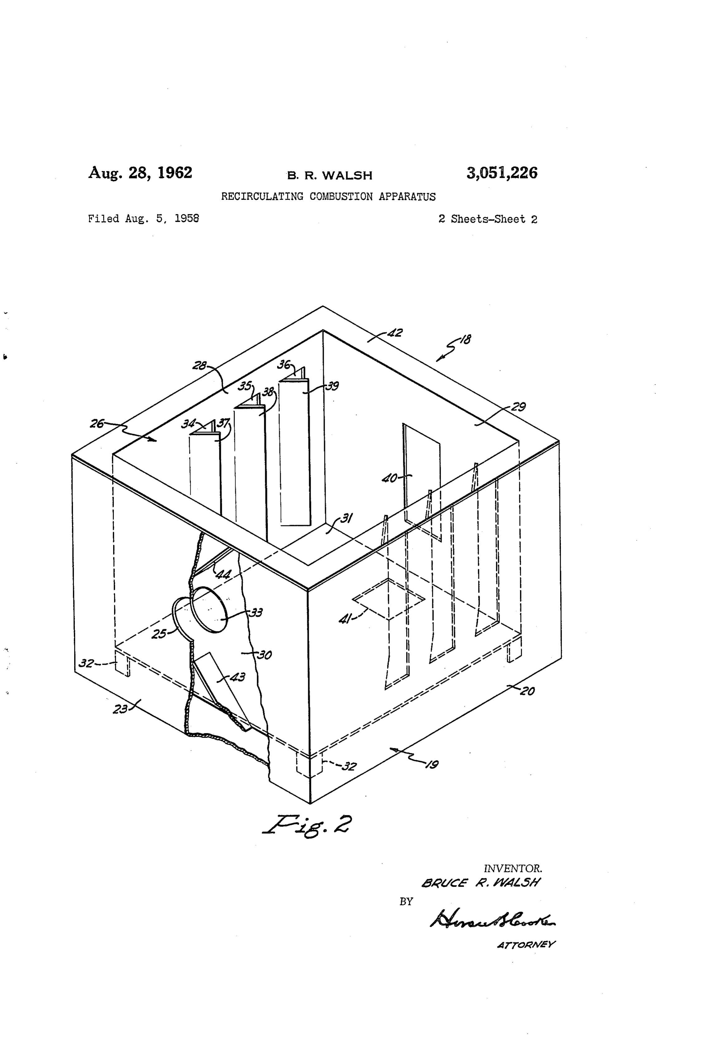
This invention relates to fuel burning apparatus and fuel and air to the combustion chamber. A smoke pipe more particularly to an improved combustion chamber O or flue stack is indicated at 17. A combustion chamber for burning fuels with air. in accordance with the invention is located within the For the generation of heat energy in fuel burning ap fire pot 3 and is designated generally by the numera. 18. paratus such as furnaces and boilers, a combustible mix Referring more particularly to FIGURES 2, 3 and 4 ture of air and a liquid or gaseous fuel are usually dis of the drawings, the combustion chamber 18 of the in charged directly into a combustion chamber wherein com 5 vention comprises an outer shell adapted to fit within the bustion of the fuel takes place. It is, of course, desirable fire pot of the furnace and an inner shell disposed therein to obtain substantially complete combustion of the fuel defining a combustion zone. The outer shell generally within the combustion chamber and it is to this end the indicated at i9 will be of suitable dimensions and shaped present invention is directed. to fit within the fire pot of the furnace. The outer shell The present invention provides a combustion cham i9 open at its top, comprises substantially upright sheet ber which is so constructed that the products of com metal side walls 28 and 21, back wall 22, front wall 23, bustion are recirculated to the combustion zone in a man and bottom wall 24. Port 25 is provided in the front ner to achieve greatly improved combustion and heating wall 23 for receiving the burner 16. efficiency. Disposed within outer shell 9 and spaced therefrom is In accordance with the invention, there is provided a 25 an inner shell designated generally at 26 which defines a combustion chamber comprising an outer shell and an zone wherein combustion of the fuel takes place. Inner inner shell disposed within and spaced from the outer shell 26 open at its top, comprises substantially upright shell to define a passage between said shells for the re sheet metal side walls 27 and 28, back wall 29, front circulation of the products of combustion. The passage wall 30, and bottom wall 3A. Secured to and depending between the shells is closed at the top and suitable open 30 from the botton wall 31 are a plurality of legs 32 by ings are provided in the inner shell to permit the hot means of which inner shell 26 is supported on the bottom gases produced upon combustion of the fuel to circulate wall 24 of outer shell 19 in spaced relationship there through the combustion gas passage and to re-enter the with. The horizontal dimensions of inner shell 26 are combustion Zone at a point near the fuel injector nozzle. Such that the upright walls thereof are spaced from the The invention will be further described with reference 35 adjacent walls of the outer shell 9 and cooperate there to the drawings wherein: with to provide a horizontal passage through which the FIGURE 1 is a vertical sectional view of a complete products of combustion are recirculated to the combus furnace employing the combustion chamber of this in tion Zone.
vention. If desired, the inner shell can be constructed without FIGURE 2 is a perspective view of the combustion 40 the bottom wall as shown in FIGURE 5, in which case, chamber of the invention. the upright side, front and back walls of the inner shell FIGURE 3 is a plan view of the combustion cham bear upon the bottom wall 24 of the outer shell. 19. It ber of the invention. is preferred, however, to have the inner shell provided FIGURE 4 is a cross-sectional view taken through 45 With a bottom wall and spaced from the bottom wall of FiGURE 3 along the plane of the line IV-V. the outer shell as this construction provides an additional FIGURE 5 is a view similar to FIGURE 4 but illus open passage underneath the inner shell for the recircula trates a modified form of the combustion chamber of tion of the hot combustion gases.
the invention. The front wall 30 of the inner shell 26 is provided with FIGURE 6 is a front sectional view of the combus port 33 which registers with port 25 in the outer shell tion chamber of the invention. 50 and through which the air-fuel mixture enters the com FIGURE 7 is a plan view of a further embodiment of bustion Zone. The burner 16, while projecting within the invention wherein the fire pot of a furnace is em the outer shell is positioned such that its discharge end ployed as one component of a combustion chamber con terminates a short distance in front of port 33 so as to structed in accordance with the invention. be capable of delivering a mixture of fuel and air to With reference to the drawings, the combustion cham 55 the interior of the inner shell without interfering with ber of the invention is illustrated in connection with a hot the flow of the combustion products. A plurality of open air type of furnace but it is to be distinctly understood ings are provided in the remaining walls of the inner shell that it is not limited to such use. The combustion cham 26 to permit the products of combustion to exit from the ber of the invention can be utilized in furnaces of the 60 combustion Zone and to pass into the combustion gas pas hot-air or hot-water types commonly employed in homes sage between the inner and outer shells. Thus, side for heating and also in other fuel burning apparatus such walls 27 and 28 of inner shell 26 are provided with a as for example, gas turbine and jet engines to improve plurality of vertically elongated slot-like openings as in the combustion efficiency thereof. dicated at 34, 35 and 36. Attached adjacent the vertical Referring to FIGURE 1, the numeral E designates a slot-like openings on the side walls and projecting in furnace of the hot-air type in which a combustion cham 65 Wardly within the inner shell 26 are louver members 37, 38 and 39. The louver members assist in directing the ber constructed in accordance with the invention is em hot combustion gases through the slot-like openings into ployed. The upper part 12 represents, more or less, the space between the inner and outer shells. In a pre diagrammatically the heating chamber of the furnace. A ferred optional construction, additional exits for the prod fire pot 13 which forms the lower section of the furnace O lucts of combustion are provided in the back and bottom is lined by refractory wall 14 and shaped to fit the con walls of the inner shell. Thus, relatively large opening tour of the furnace in which it is placed. The configura 40 is provided in back wall 29 of the inner shell op
Page 4scan →
3,051,226 posite port 33. Similarly, the bottom wall 31 of the inner adjacent the openings 50 and 51 and 52 respectively, and shell 26 can be provided with an opening as indicated serve to direct combustion gases through these openings at 41. into the combustion gas passage. The entire outer sur Extending horizontally and joining the top portions of face of the walls comprising the inner shell 46 are spaced the upright walls of the inner and outer shells is top 42. from the corresponding wall portions of the fire pot 45 Top member 42 extends continuously along the marginal with the exception of the top 56. Top 56 is attached edges of the top portions of the upright walls of the inner along the upper ends of the upright walls of the inner and outer shells and is attached thereto by suitable means shell 46 and extends horizontally therefrom to have its to form an air tight seal. Top member 42 thus coop outer ends in engagement with the wall portions of fire erates with the upright walls of the inner and outer shell O pot 45. To prevent leakage of the hot combustion gases, to form a closed or roofed passage which extends entirely top 56 is cemented or joined by other suitable means to around the inner shell. As shown in FIGURE 6, de the fire pot 45. Thus, top member 56 cooperates with flectors 43 and 44 are provided on the exterior surface the upright walls of the fire pot 45 and inner shell 46 of front wall 30 of inner shell 26 to direct the flow of to form a closed combustion gas passage. hot combustion gases toward port 33 through which the 5 It will be apparent to those skilled in the art that combustion gases pass into the combustion zone. various modifications can be made in the combustion For convenience in installation, both the inner and chamber of the invention. Thus, for example, the outer outer shell members can be made in sections so that the and inner shells comprising the combustion chamber combustion chamber may be assembled in existing heat of the invention can be made of ceramic material instead ing units after fabrication thereof. Thus, the inner and 20 of sheet metal as previously indicated. Moreover, the outer shells of the combustion chamber may comprise number of openings provided within the walls of the inner upper and lower matching sections or front and rear shell can be varied as desired. - matching sections of a size to readily pass through the From the foregoing description, it is apparent that openings, normally provided in the front of the heating the invention provides a novel combustion chamber of unit. Upon installing the combustion chamber the match 25 simple construction which can be readily installed in fur ing sections are brought together to complement one naces to improve the combustion efficiency of the fur another and to form the combustion chamber in accord naces. In the aforedescribed combustion chamber the ance with the invention. hot products of combustion are recirculated through the In operation of a fuel burning apparatus equipped with chamber and subjected to combustion a second time a combustion chamber constructed in accordance with 30 thereby assuring substantially complete combustion of the the invention, burner 6 delivers a mixture of fuel and fuel. An additional advantage of the novel combustion air into the inner shell 26 wherein combustion of the fuel chamber is that the hot products of combustion upon re occurs. As the flame progresses rearwardly within the entering the combustion zone at a point near the fuel in inner shell, the hot products of combustion pass through jector nozzle, supply heat to the incoming fuel and air the relatively large opening 40 provided in the back wall 35 thus assisting in the combustion of the fuel. Further 29 by the inner shell into the space defined by the walls more, in the combustion chamber of the invention, the of the inner and outer shells and the top member 42. hot combustion gases are prevented from being imme The portion of the combustion products which impinge diately exhausted up the stack thus resulting in the fur upon the back wall of the inner shell and reflect there nace having lower stack temperatures. from, pass out through the openings 34, 35, 36 and 4 40 Those modifications and variations which fall within provided in the side and bottom walls respectively. The the spirit of the invention and the scope of the appended inwardly projecting louver members 37, 38 and 39 serve claims are to be considered part of the invention. to direct the combustion products through the openings I claim:
34, 35 and 36 provided in the side walls of the inner 1. A fuel burning apparatus comprising an outer shell, shell. The combustion gases upon entering the space an inner shell having generally upright wall means dis between the inner and outer shells are constrained to flow posed within said outer shell and spaced therefrom to de horizontally toward the front of the combustion chamber fine a passage extending around the outer periphery of and eventually re-enter the combustion zone through port said upright wall means, the inside of said inner shell be 33 provided in the front wall 30 of the inner shell 26. ing a combustion chamber and said passage around said In this manner, the products of combustion are again 50 upright Wall means adapted to serve as a recirculation subjected to combustion, thus providing a form of two passage for combustion gases from said combustion cham stage combustion and assuring substantially complete fuel ber, means closing the upper and lower ends of said re combustion. In addition, the hot combustion gases re circulation passage, first opening means in said upright entering the combustion Zone at a point near the fuel wall means adapted for the horizontal admission of fuel injector nozzle convey heat to the incoming fuel and 55 to said combustion chamber, said first opening means air and prime the mixture for combustion. establishing an inlet to said combustion chamber from In FIGURE 7, a further modification of the invention said recirculation passage, second opening means in said is illustrated. In this embodiment of the invention the upright wall means establishing an outlet from said com walls defining the fire pot of the furnace serve as the bustion chamber to said recirculation passage, said re outer shell of the improved combustion chamber. Re 60 circulation passage providing a path for circulation of ferring specifically to FIGURE 7, the fire pot of the combustion gases from said second opening means to furnace made of refractory ceramic material and of said first opening means, said inner shell having an open hexagonal shape is indicated at 45. Disposed within top establishing overhead exhaust removal means from fire pot 45 and spaced therefrom is the inner shell 46. said combustion chamber, the only access between said Inner shell 46 can be made of ceramic material also or 65 Overhead exhaust removal means and said recirculation can be of sheet metal construction. The front wall of passage being through said combustion chamber. the inner - shell 46 is provided with port 47 which is 2. Claim 1 wherein said second opening means is dis aligned with port 48 in the front wall of fire pot 45. posed in said combustion chmaber in a position generally The opposed back wall of inner shell 47 is provided with opposite to said first opening means. a relatively large opening as indicated at 49 which com 70 3. Claim 1 wherein a nozzle is disposed substantially municates with the combustion gas passage between the horizontally at said first opening means adapted for spray inner shell 46 and the walls of the fire pot 45. Elongated ing a liquid fuel substantially horizontally into said com slot-like openings are provided along the remaining sides bustion chamber.
of the inner shell as indicated at 50, 51 and 52. Inwardly 4. A fuel burning apparatus comprising an outer shell projecting louver members 53, 54 and 55 are attached 75 having generally upright walls and a bottom wall, an 5 inner shell having generally upright wall means disposed being a combustion chamber and the passage around the within said outer shell and spaced therefrom to define a periphery of said upright wall means and said bottom passage extending around the outer periphery of said wall means adapted to serve as a recirculation passage upright wall means, the inside of said inner shell being a for combustion gases from said combustion chamber, combustion chamber and said passage around said up horizontal closure means continuously extending between right wall means adapted to serve as a recirculation pas the upper portion of the upright wall means of said inner sage for combustion gases from said combustion cham shell and the upright walls of said outer shell to en ber, means closing the upper and lower ends of said re close the top of said recirculation passage, first opening circulation passage, first opening means in said upright means in said upright wall means adapted for the hori wall means adapted for the horizontal admission of fuel 10 zontal admission of fuel to said combustion chamber, to said combustion chamber, said first opening means said first opening means establishing an inlet to said com establishing an inlet to said combustion chamber from bustion chamber from said recirculation passage, second said recirculation passage, second opening means in said opening means in said upright wall means establishing an upright wall means establishing an outlet from said com outlet from said combustion chamber to said recirculation bustion chamber to said recirculation passage, said recir 5 passage, said recirculation passage providing a path for culation passage providing a path for circulation of com circulation of combustion gases from said second open bustion gases from said second opening means to said ing means to said first opening means, said inner shell first opening means, said inner shell having an open top having an open top establishing overhead exhaust removal establishing overhead exhaust removal means from said means from said combustion chamber, the only access be tween said overhead exhaust removal means and said re combustion chamber, the only access between said over 20 circulation head exhaust removal means and said recirculation pas ber. passage being through said combustion cham sage being through said combustion chamber. 10. A fuel burning apparatus comprising an outer shell, 5. Claim 4 wherein said upright inner shell wall means are shorter than said outer shell upright walls. an inner shell having generally upright wall means dis 6. Claim 4 wherein an opening exists in an upright 25 posed within said outer shell and spaced therefrom to define a passage extending around the outer periphery wall of the outer shell in register with the first opening of said upright wall means, the inside of said inner shell means in the upright wall means of the inner shell.
7. A fuel burning apparatus comprising an outer shell being a combustion chamber and said passage around said having generally upright walls and a botton wall, an upright wall means adapted to serve as a recirculation inner shell having generally upright wall means and bot 30 passage for combustion gases from said combustion cham tom wail means disposed within said outer shell and ber, means closing the upper and lower ends of said re Spaced therefrom to define a passage extending around circulation passage, first opening means in said upright the outer periphery of said upright wall means and said wall means adapted for the horizontal admission of fuel bottom wall means, support means for supporting said 35 to said combustion chamber, said first opening means establishing an inlet to said combustion chamber from inner shell, the inside of said inner shell being a com said recirculation passage, second opening means in said bustion chamber and said passage around the outer pe upright wall means in a position in said combustion riphery of said upright wall means and said bottom wall chamber opposite to said first opening means establishing means adapted to serve as a recirculation passage for com an outlet from said combustion chamber to said recircu bustion gases from said combustion chamber, means clos 40 lation ing the upper end of said recirculation passage, first open rality ofpassage, third opening means comprising a plu ing means in said upright wall means adapted for the said firstopenings in said upright wall means intermediate and said second opening means, each of the horizontal admission of fuel to said combustion cham ber, said first opening means establishing an inlet to said openings oflouver said third opening means having an inwardly combustion chamber from said recirculation passage, 45 projecting adjacent thereto directed toward said second opening means, said recirculation passage provid second opening means in said upright wall means estab ing a path for circulation of combustion gases from said lishing an outlet from said combustion chamber to said second opening means and said third opening means to recirculation passage, said recirculation passage provid said first opening means, said inner shell having an open ing a path for circulation of combustion gases from said top
Second opening means to said first opening means, said 50 said establishing combustion overhead exhaust removal means from chamber, the only access between said inner shell having an open top establishing overhead ex haust removal means from said combustion chamber, the overhead exhaust removal means and said recirculation passage being through said combustion chamber.
only access between said overhead exhaust removal means and said recirculation passage being through said com References Cited in the file of this patent bustion chamber.
8. Claim 7 wherein an opening exists in said bottom 55 UNITED STATES PATENTS wall means of the inner shell providing an additional 1,671,448 Plassmann -------------- May 29, 1928 outlet from said combustion chamber to said recircula 1901,922 Mekler ---------------- Mar. 21, 1933 tion passage. 1959,033 McGuiness ------------ May 15, 1934 9. A fuel burning apparatus comprising an outer shell 60 2247,977 Uschold et al. ---------- July 1, 1941 having generally upright walls and a bottom wall, an 2,424,765 McCollum ------------ July 29, 1947 inner shell having generally upright wall means and bot 2,601,667 Permann -------------- June 24, 1952 tom wall means disposed within said outer shell and 2,648,599 Throckmorton et al. --- Aug. 11, 1953 spaced therefrom to define a passage extending around 2,701,608 Johnson ---------------- Feb. 8, 1955 the outer periphery of said upright wall means and said 65 2,808,046 Jaye ------------------ Oct. 1, 1957 bottom wall means, legs supporting the bottom wall 2,857,961 Brown et al. ----------- Oct. 28, 1958 means of said inner shell, the inside of said inner shell 2,918,117 Griffin ---------------- Dec. 22, 1959
Provenance
- Collection
- Patents citing this work
- Pages
- 5
- Method
- pdftotext (the PDF's own text layer) + pdftoppm 300dpi page scans
- Patent office record
- patents.google.com →
- Source
- Google Patents citing-documents table
- Assignee
- Gulf Research Development Co
- Published
- 1962-08-28
- Transcribed from
- patentimages.storage.googleapis.com →