

patent · US3366154A
Recirculating burner
30 January 1968
Text
Drawings
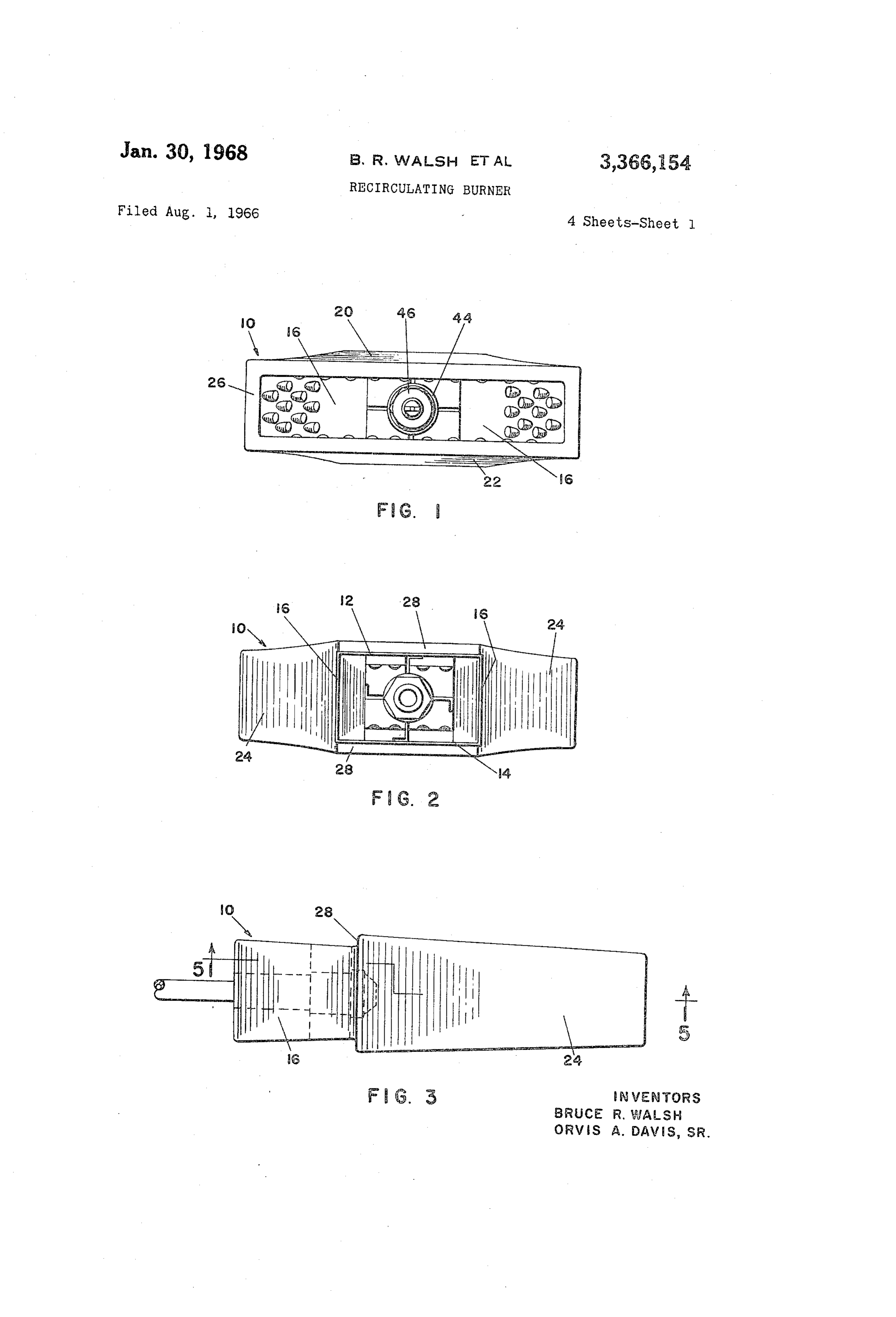
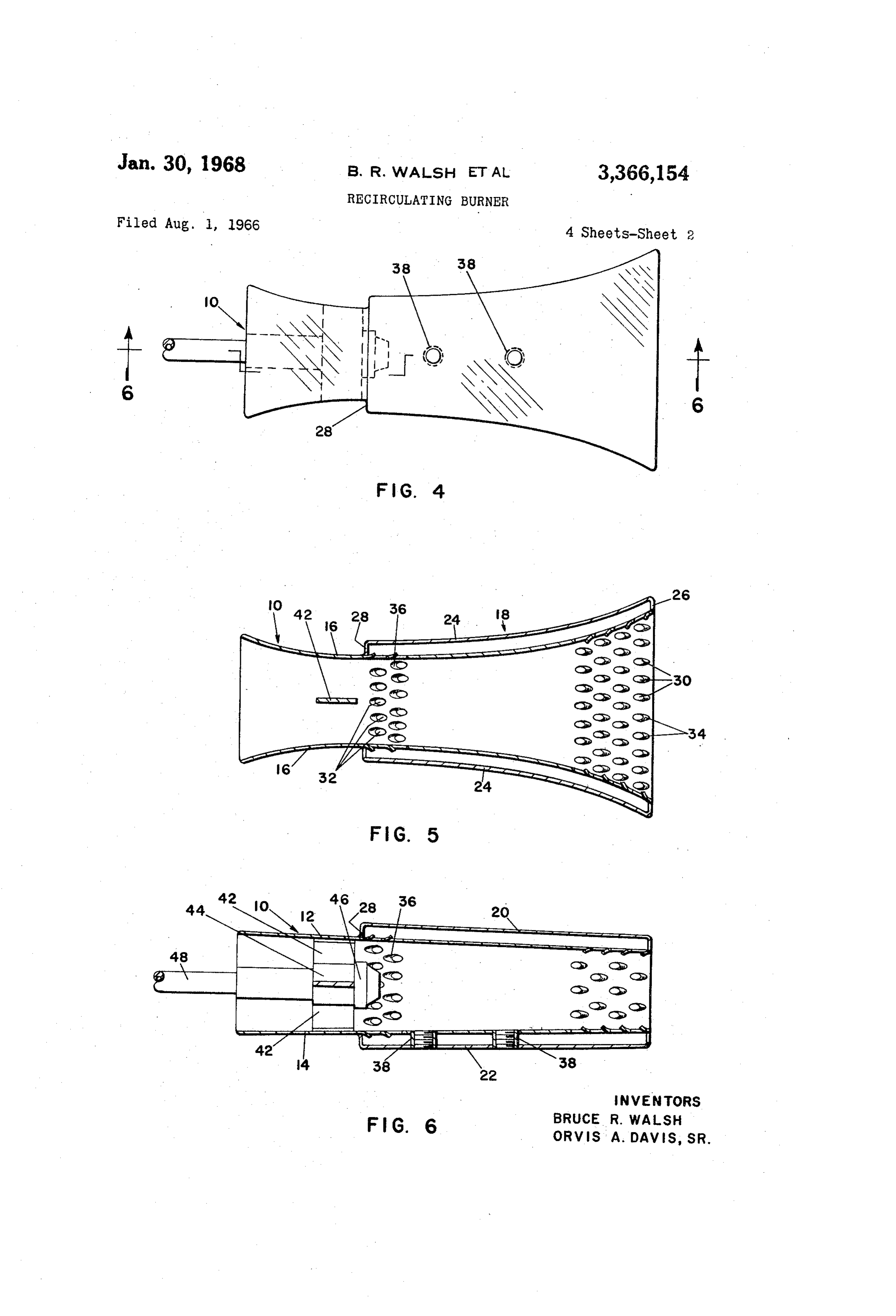
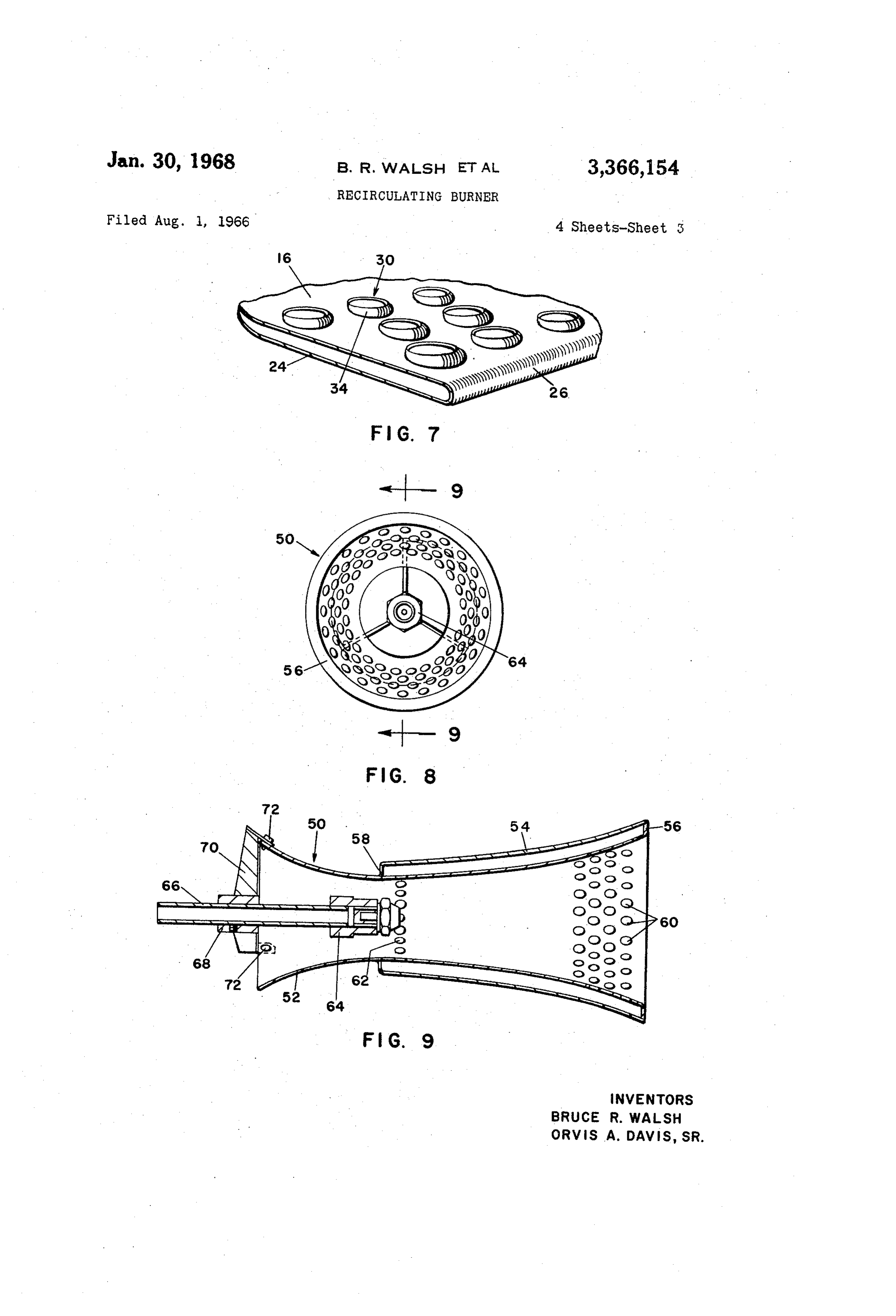
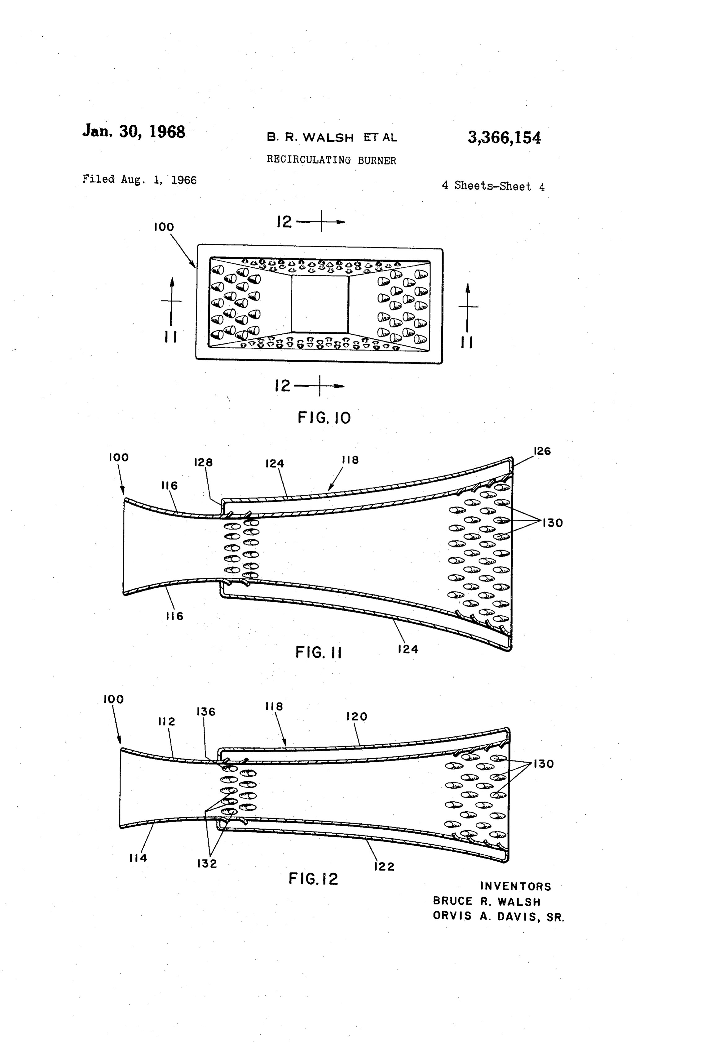
FIG. 9 is a cross-sectional view taken on line 9-9 of Referring to FIG. 5 it will be seen that side walls 16
Page 1drawing sheetscan →
Page 2drawing sheetscan →
Page 3drawing sheetscan →
Page 4drawing sheetscan →
Page 5scan →
United States Patent Office 3,366,154 Patented Jan. 30, 1968
3,366,154 FIGS. 11 and 12 are cross-sectional views taken on RECIRCULATING BURNER lines 1-11 and 12-12 of FIG. 10 respectively. Bruce R. Walsh, Pittsburgh, and Orvis A. Davis, Sr., Referring now in detail to the drawing, 10 designates Gibsonia, Pa., assignors to Gulf Research & Develop a burner embodying the invention. Burner 10 comprises ment Company, Pittsburgh, Pa., a corporation of top and bottom walls 12 and 14 respectively, and a pair Delaware of similar, symmetrically disposed side walls 16 joining the Filed Aug. 1, 1966, Ser. No. 569,386 longitudinal edges of the top and bottom walls. Walls 12, 18 Claims. (CI. 158-1) 14, and 16 extend the entire length of burner 10, to pro vide an axial opening therethrough.
AESTRACT OF THE DISCLOSURE 10 Means are provided to provide recirculation of some A compact portable burner useful in flame cultivation of the products of combustion from the discharge end of crops, comprising an elongated hollow body formed of the burner to a position mediately the end thereof at the venturi throat and just forwardly of the face of the with a venturi throat, and a recirculation jacket surround ing the body from the throat to the front end. The body 15 nozzle, as will appear more clearly below, for the pur poses of providing a clean flame and more efficient burn wall is formed with recirculation entrance openings at the ing of fuel, to provide improved vaporization of fuel, front end, and with recirculation exit openings at the greater turbulence, and similar advantages. To this end, venturi throat to recirculate products of combustion. A a recirculation jacket 18 surrounds this portion of the nozzle is positioned at the openings at the venturi throat. burner, and comprises a top wall 20, a bottom wall 22, 20 and a pair of similar symmetrically disposed side walls
This invention relates to burners, paricularly adapted 24, joining the ends of walls 20 and 22. Walls 20, 22, and for use in flame weeding, and other applications wherein 24 are similar in configuration to the adjacent portions of and are in a predetermined outwardly spaced relation a clean flame substantially free of unburned fuel and hot to, walls 12, 14, and 16, respectively. The front ends of carbon particles is desirable; and which are adapted to the jacket walls and the burner walls are joined together burn oil as the fuel. by a front shoulder 26. The rear ends of the jacket walls The technique of flame cultivation for the control of 12, 14, and 16 at a predetermined position along the weeds in crops such as cotton, corn, grain sorghum, etc., axis of the burner rearwardly of the venturi throat, by a has been extensively studied and developed in recent rear shoulder 28. Walls 12, 14, and 16 are provided with times. However, most commercially available burners a plurality of openings 30 adjacent and slightly rearwardly designed for this purpose use liquefied petroleum gas 30 of front shoulder 26, and with a plurality of openings (LPG) as the fuel. However, LPG is undesirable as a 32 adjacent and slightly forwardly of rear shoulder 28. fuel for several reasons, for example; the fear of fire and Openings 30 and 32 may be plain circular openings, such explosion in its use and storage, its higher cost in some as openings 60 and 62 in the second embodiment of areas as compared to the cost of fuel oil, and its unavail 35 FIGS. 8 and 9, or may have offset edges on one side as ability in certain areas. in the embodiments of FIGS. 1 to 7, and openings 130 Therefore, it is an object of this invention to provide and 132 in FIGS. 10 to 12. The openings 30 are arranged a burner of the character described which is at least as in four rows around the front of the burner, and open efficient in its operation as LPG burners heretofore avail ings 32 are arranged in two rows at the venturi throat of able, while avoiding the use of EPG and preferably using 40 the burner. More openings are provided at the front than oil, as fuel. at the throat to accommodate the increase in volume of Another object of this invention is to provide a burner the burning air and oil at the discharge end of the burner, of the character described comprising means to utilize and because of physical limitations of locating openings the venturi principle to cause recirculation of some of the in the venturi throat. The beginning of the flame is located products of combustion from the discharge end of the 45 within the discharge end of the burner at about the loca burner back to the vicinity of the nozzle, at which vicinity tion of openings 30.
the venturi throat is located, to provide a heated second Referring to FIG. 7, it will be seen that each opening ary air supply, to cause improved vaporization of the fuel 30 has a raised offset portion 34 at the front side of the oil, to cause increased turbulence in the air-oil mixture opening. Portion 34 acts a scoop with respect to the com for more efficient mixing, and to provide a clean flame. bustion passing over these openings. Openings 32 are simi The above and other objects and advantages of the lar in structure to openings 30, but the rear openings have present invention will in part become apparent and will their offset portions 36 disposed at the rear of the open in part be pointed out in the following detailed descrip ings, since the recirculated combustion products must exit tion, reference being had to the accompanying drawing from these openings after having entered openings 30 and forming a part thereof in which: 55 recirculated through jacket 18, back into the main stream FIG. 1 is a front elevational view of a burner embody passing through the burner. Offset portions 36 are de ing the invention; pressed into the recirculation jacket to scoop combustion FIG. 2 is a rear elevational view thereof; products passing over them.
FIG. 3 is a side elevational view thereof; A pair of threaded sleeves 38 are mounted in suitable FIG. 4 is a bottom plan view thereof; 60 openings formed in walls 14 and 22, and receive any suit FIG. 5 is a cross-sectional view taken on line 5-5 of able ignition means, such as as electrodes or a spark plug FIG. 3; in which event only one sleeve 38 would be provided. FIG. 6 is a cross-sectional view taken on line 6-6 of Sleeves 38, while they are positioned in the recirculation FIG. 4; chamber, are small enough so that they present a negligi FIG. 7 is a partial perspective view of a detail; 65 ble obstruction to the flow of gases therein. FIG. 8 is a front elevational view of a first modified Burner 10 is a self-contained, compact unit, and can be construction; mounted in any suitable manner, such as by a bracket se cured to any external wall.
FIG. 9 is a cross-sectional view taken on line 9-9 of Referring to FIG. 5 it will be seen that side walls 16
FIG. 10 is a front elevational view of a second modi 70 flare outwardly both forwardly and rearwardly from a fied construction; and narrowed throat portion which is located in spaced rela tion to the front end of the burner, and which functions 6 as the venturi. Referring to FIG. 6, it will be seen that are present in the actual burner, and may be the same as walls 12 and 14 are flat and slope towards each other the analogous parts of the first two embodiments. from rear to front over their entire length, thus defining Comparison of FIGS. 5 to 11 show that side walls 16 a larger space between them at their rear ends, and a and 116 are similar in configuration, and the burner 100 smaller space between them at their front ends. The walls is about the same as burner 10 in a horizontal plane. 20, 22, and 24 of jacket 18 follow the curvature or in Comparison of FIGS. 6 and 12 shows that top and bot clination of the respective portions of walls 12, 14, and tom walls 112 and 114 flare outwardly away from each 16, respectively, between the front and rear shoulders 26 other both forwardly and rearwardly from the area of and 28. Thus, burner 10 functions as a venturi in a hori rear openings 132, which is the area of the venturi throat. Zontal plane, and functions as a nozzle in a vertical plane, 0. Top and bottom walls 12 and 14 of burner 10 are flat which structure tends produce a vertically compressed and slope towards each other over their entire length and horizontally spread flame which is particularly from rear to front, as described above. Thus, the major adapted for use in flame weeding, and other applications difference between burners 10 and 100 is that burner 100 such as bakery ovens, kilns, and the like. The outwardly functions as a venturi in both the horizontal and vertical flaring configuration of walls 16 and the spreading con planes to produce a rectangular flame spread both ver figuration of walls 12 and 14 rearwardly of rear shoulder tically and horizontally.
28 create increasing rectilinear cross-sectional areas rear Just as in burner 10, the walls 120, 122, and 124 of wardly of said shoulder, which provides for a large intake recirculation jacket 118 of burner 110 follow the curva of Secondary air through the rear end of the burner, and ture of the respective portions of walls 112, 114, and 116, which enhances the operation of the venturi. 20 respectively, between front and rear shoulders 126 and Burner 10 could be used with many fuels, but advan 128.
tageously, oil is used for the reasons set forth above. Burner 100 is suitable for use in many applications such Means are provided to mount a fuel oil nozzle at the ven as flame Weeding of crops, and boilers or furnaces where turi throat. To this end, four struts 42 are provided, each in the combustion space available is better suited to the having its outer end joined to one of the walls 12, 14, or 25 flame of burner 100 than to the flame of burner 50. In 16, and its inner end joined to a nozzle mounting collar flame weeding applications the choice of burner will be 44. Mounted and suitably secured in collar 44 by any determined by the particular nature of the crop and weed Suitable means is a nozzle 46 which is joined to a fuel oil combination to be flamed, as will be evident to those Supply pipe 48, and a primary air supply pipe, now shown, skilled in the art.
if necessary. It has been found that burner 10 embodying While the invention has been described in some detail this first form of the invention works most efficiently above, it is to be understood that the protection granted when nozzle 46 is of the type which produces a flat spray. is to be limited only within the spirit of the invention The nozzle disclosed in U.S. patent application Ser. No. and the scope of the following claims. 524,672, filed Feb. 3, 1966, entitled, “Nozzle,” by Orvis 35 We claim:
A. Davis, Sr., and assigned to the same assignee as the 1. A self-contained burner comprising an elongated hol present invention, has produced satisfactory results when low body having front and rear axially aligned open ends used with burner 10 in flame weeding of crops. to permit the passage of ambient air therethrough, said Referring to FIGS. 8 and 9 there is shown a burner 50, body comprising longitudinal continuous wall means comprising a second embodiment. Burner 50 comprises whose ends define said front and rear openings, the vol a wall 52 flaring outwardly both forwardly and rear ume within said hollow body defined by said wall means being Symmetrical about planes containing the longitudi
Wardly from a throat or venturi, similar to the structure of burner 10 in a horizontal plane, as shown in FIG. 5. A nal axis of said body, said wall means defining a narrowed recirculation jacket 54 surrounds wall 52 betwen the front throat portion within said hollow body in spaced rela end of the burner and the throat, and is supported thereon tion to the open front end thereof, and means to recir in Spaced relation thereby by a front shoulder 56 and a culate fluids passing through said body from points lo cated closely adjacent to and rearwardly of said front rear shoulder 58. Wall 52 is provided with a plurality of open openings 60 arranged in four rows adjacent the discharge end to points located substantially at and forwardly end of the burner, and with a single row of openings 62 of said throat portion.
adjacent the throat, for the same reasons explained above 2. The combination of claim 1, said recirculation regarding openings 30 and 32. In place of the single row 50 ‘means comprising jacket means surrounding said wall 62, two or more rows could be provided for increased means from Said open front end to said throat portion, circulation, if necessary, depending on the nozzle used. said jacket means comprising a jacket wall Spaced from A nozzle 64, mounted on a supply pipe 66, has its front said wall means and a pair of jacket end walls inter end positioned adjacent openings 62. The nozzle is held connecting the ends of said jacket wall and said wall in burner 50 by means of a set screw collar 68 to which 55 means, to define a single recircultaion chamber between are joined three struts 70, each having its outer end se said jacket means and said portion of said wall means, cured to the rear end of burner 50 by any suitable means Said recirculation means further comprising a first plu Such as Screws 72. Burner 50 will produce a conical flame rality of openings formed in said wall means adjacent said Open front end communicating said recirculation cham which will have its combustion products recirculated just ber as combustion products of burner 10 are recirculated. 60 with the space within said body adjacent said front Burner 50 is suitable for use in applications where the open end, and a second plurality of openings formed in flat flame produced by burner 10 is not the most desirable said wall means adjacent said throat portion communi flame, such as in a water boiler or furnace where it is cating the Space within said body adjacent said throat desirable to have a flame which is shaped to suit the com portion with the rear of said recirculation chamber. bustion space available; for example, where there is no 65 3. The combination of claim 2, the portions of said firebox. Wall means Surrounding each of the openings of said first Referring to FIGS. 10 to 12. there is shown a burner and Second plurality of openings being offset from the 100, comprising a third embodiment. Burner 100 is smiliar plane of said wall means on one side of each of said to burner 10 of FIGS. 1 to 7, and similar parts are indi openings.
cated by the same reference numeral increased by 100. 70 4. The combination of claim 1, the volume defined The nozzle, the struts, or other means mount the nozzle by said wall means being substantially rectilinear in all with its front face in the vicinity of the venturi throat planes perpendicular to said axis. and rear openings 136, and the ignition means mounting 5. The combination of claim 1, the volume defined sleeves analogous to sleeves 38, have been omitted from by said wall means being substantially circular in all burner 100, but it is to be understood that these parts 75 planes perpendicular to said axis.
Page 7scan →
6. The combination of claim 1, said wall means com 13. The combination of claim 2, in combination with prising a first pair of flat, horizontally disposed walls in nozzle means, said burner comprising means to position clined towards each other from said throat portion to the front face of said nozzle means substantially at said wards said open front end and a second pair of curved second plurality of openings.
vertically disposed walls joining the longitudinal edges of 14. The combination of claim 9, said first pair of flat said horizontal walls and flaring outwardly from said horizontally disposed walls diverging away from each throat portion towards said open front end, whereby a other from said throat portion towards said open rear flame issuing from said burner is of rectangular shape end, and said second pair of vertically disposed walls flar and vertically compressed and horizontally spread out. ing outwardly from said throat portion towards said open 7. The combination of claim 1, said wall means driverg rear end, whereby the cross-sectional area of said body ing apart from said throat portion towards both said open 10 increases from said throat portion towards both said open rear end and said open front end, whereby the cross-sec rear end and said open front end. tional area of said body increases from said throat portion 15. The combination of claim 10, said first pair of towards both said open rear end and said open front end. horizontally disposed walls flaring away from each other 8. The combination of claim 1, said wall means com from said throat portion towards said open rear end, and prising a first pair of curved horizontally disposed walls said second pair of vertically disposed walls flaring away flaring outwardly from said throat portion towards said from each other from said throat portion towards said open front end, and a second pair of curved vertically open rear end, whereby the cross-sectional area of said disposed walls joining the longitudinal edges of said hori body increases from said throat portion towards both zontal walls and flaring outwardly from said throat por 20 said open rear end and said open front end. tion towards said open front end, whereby a flame issu 16. The combination of claim 4, said wall means com ing from said burner is of rectangular shape and ver prising a first pair of curved horizontally disposed walls tically and horizontally spread out. flaring outwardly from said throat portion towards said 9. The combination of claim 2, said wall means com open front end, and a second pair of curved vertically dis prising a first pair of flat horizontally disposed walls in 25 posed walls joining the longitudinal edges of said hori clined towards each other from said throat portion to Zontal walls and flaring outwardly from said throat por wards said open front end and a second pair of curved tion towards said open front end, whereby a flame issuing vertically disposed walls joining the longitudinal edges of from said burner is of rectangular shape and vertically said horizontal walls and flaring outwardly from said and horizontally spread out.
throat portion towards said open front end, whereby a 30 17. The combination of claim 2, each opening of said flame issuing from said burner is of rectangular shape and first plurality of openings comprising an offset portion vertically compressed and horizontally spread out. at the side thereof closest to said front open end, and 10. The combination of claim 2, said wall means com each of said offset portions of said first plurality of open prising a first pair of curved horizontally disposed walls ings extending into said hollow body. flaring outwardly from said throat portion towards said 18. The combination of claim 17, each opening of said open front end, and a second pair of curved vertically dis second plurality of openings comprising an offset por posed walls adjoining the longituding edges of said hori tion at the side thereof furthest from said front open end, zontal walls and flaring outwardly from said throat por and each of Said offset portions of said second plurality tion towards said open front end, whereby a flame issu of openings extending into said recirculation chamber. ing from said burner is of rectangular shape and vertical 40 ly and horizontally spread out. References Cited 11. The combination of claim 4, said wall means com UNITED STATES PATENTS prising a first pair of flat horizontally disposed walls in 2,516,063 7/1950 Logan et al. ---------- 158-76 clined towards each other from said throat portion to wards open front end and a second pair of curved ver 45 2,867,267 2/1955 tically disposed walls joining the longitudinal edges of 2,918,117 12/1959 Griffin --------------- 158-1 said horizontal walls and flaring outwardly from said 2,925,858 2/1960 Reed ---------------- 158-1 throat portion towards said open front end, whereby a 3,174,527 3/1965 Reed et al. -------- 158-11 flame issuing from said burner is of rectanguar shape and is vertically compressed and horizontally spread out. 50 FOREIGN PATENTS 12. The combination of claim 1, in combination with 1,129,673 9/1956 France.
fuel oil nozzle means, said burner comprising means to position said nozzle means with the front face of said noz FREDERICKL. MATTESON, JR., Primary Examiner. zle means substantially at said recirculation means at said throat portion. E. G. FAVORS, Assistant Examiner.
Provenance
- Collection
- Patents citing this work
- Pages
- 7
- Method
- pdftotext (the PDF's own text layer) + pdftoppm 300dpi page scans
- Patent office record
- patents.google.com →
- Source
- Google Patents citing-documents table
- Assignee
- Gulf Research Development Co
- Published
- 1968-01-30
- Transcribed from
- patentimages.storage.googleapis.com →