

patent · US3994665A
Recirculating burner
30 November 1976
Text
Page 1bibliographic recordscan →
United States Patent (19)
Young
54 RECIRCULATING BURNER
(75. Inventor: Henry J. Young, Marblehead, Mass. Assignee: Consolidated Natural Gas Service Co., Inc., Pittsburgh, Pa.
(52) U.S. Cl..................................... 431/116; 43.1/9;
(5ll Int. Cl”............................................ F23L 7700
UNITED STATES PATENTS
1839,512 l 11932 Waterman .......................... 4311 15 2,216, 178 10/1940 Astradsson... ... 431 || 1 3,620,657 l l 1971 Robinson................................ 43119 3,652,194 3/1972 Bailey..................................... 43 119 3,705,784 12/1972 Reichhelm.......................... 431 fl 16
Primary Examiner-Edward G. Favors
A recirculating burner for burning a vaporizable liquid fuel comprising a housing, a combustion chamber in the housing, with inlet and outlet, a vaporizing cham ber, with inlet and outlet, an air inlet for directing air
anaann SSSSSSS
under pressure into the combustion chamber, a fuel inlet atomizer, adjacent to the vaporizing chamber in let, for automizing vaporizable liquid fuel and direct ing the fuel into the vaporizing chamber, a gaseous fuel inlet for feeding gaseous fuel into the combustion chamber, a first passage interconnecting the combus tion chamber toward the combustion chamber outlet with the vaporizing chamber inlet, for receiving hot combustion gases from the combustion chamber, a second passage effectively interconnecting the vapor izing chamber outlet with the combustion chamber in let, the air inlet communicating with the second pas sage, and a vortex generator at the interface of the fuel inlet atomizer, the first passage, and the vaporiz ing chamber inlet, the generator being rotatable with respect to the housing between two positions, a first open position in which the generator receives hot gases from the first passage and swirls them into a vor tex, into which the fuel atomizer directs atomized fuel, for vaporization of the fuel by the gases in the genera tor and vaporizing chamber, and the first passage, gen erator, vaporizing chamber, and second passage to gether define a recirculation path for hot combustion gases from the combustion chamber, and a second closed position in which the generator blocks the re circulation path, and the gaseous fuel inlet feeds gase ous fuel into the combustion chamber for burning therein.
6 Claims, 5 Drawing Figures
Drawings
Page 2drawing sheetscan →
Page 3scan →
receives hot gases from the first passage and swirls
RECIRCULATING BURNER them into a vortex, into which the fuel inlet atomizer
Background of the invention
directs atomized liquid fuel, for vaporization of the fuel by the gases in the vortex generator and vaporizing
This invention relates to recirculating liquid fuel 5 chamber, and the first passage, generator, vaporizing burners, and provides an improvement in certain re chamber, and second passage together define a recircu spects in the burner claimed in the U.S. patent applica lation path for hot combustion gases from the combus tion of Andrew J. Syska, entitled “Recirculating tion chamber to the vaporizing chamber and back to Burner" and filed Sept. 4, 1975, Ser. No. 610,250. 10 the combustion chamber, where vaporized fuel is Recirculation of hot combustion gases is a known burned with air from the air inlet, and a second closed means of vaporizing liquid fuel for better combustion position in which the vortex generator blocks gas flow thereof, but such recirculation is unnecessary and may from the first passage to the vaporizing chamber, be detrimental when the fuel is already a gas, such as thereby blocking the recirculation path, and the gase natural gas. It is desirable to provide a simple means of 15 ous fuel inlet feeds gaseous fuel into the combustion converting a burner from a recirculating mode for chamber for burning therein with air from the air inlet. burning a liquid fuel to a non-recirculating mode for In a preferred embodiment the vortex generator has burning a gaseous fuel. Andrew J. Syska, in his above a cylindrical body and the fuel inlet atomizer includes a mentioned patent application, suggested the use of nozzle, the body containing a throat and a generally sliding gates alternately to open or close the recircula 20 tubular tion passages interconnecting the section of his burner body, thevortex body chamber extending axially within the being rotatable about its axis between where vaporization of liquid fuel occurs from the sec the two positions, the fuel inlet atomizer is connected tion where combustion occurs, thereby to permit or to one end of the vortex chamber, the vaporizing cham block recirculation. ber inlet is connected to the other end of the vortex SUMMARY OF THE INVENTION 25 chamber, the throat is directed into the vortex chamber The invention provides a safe, clean, simple, com tangentially tion, the of the chamber, and in the first open posi throat interconnects the first passage and the pact, easy-to-manufacture, convenient-to-use, and ver satile recirculating liquid fuel burner capable of pro vortex chamber along the wall of the vortex chamber ducing blue-flame, smoke-free, and quiet combustion. 30 between the ends of the chamber, and the nozzle pro The invention provides a burner capable of burning duces a generally conical spray of atomized liquid fuel, liquid or gaseous fuels. Switching from one type of fuel whereby in the first open position hot combustion gases to the other is simple and quick to accomplish, without are accelerated through the throat to form the vortex in the need for a lot of complex adaptor equipment. The the vortex chamber, and the vortex swirls about the burner has a turndown range up to 4.5:1, and is capable conical spray of fuel, providing vaporization thereof of maintaining blue-flame combustion throughout the 35 before the fuel can hit a wall, and in the second closed range. Vaporization of liquid fuel is complete, un position the body blocks flow of hot combustion gases wanted condensation of such fuel along the burner from the first passage to the vaporizing chamber; the walls is prevented, and combustion is thereby made vortex generator includes an end plate connected to more efficient. Start-up is efficient, without waste of 40 the end of the body at which the fuel inlet atomizer is oil, and does not require complex or cumbersome start connected, for common rotation with the body, the end ing equipment. High flame temperatures can be plate and the body each have an opening permitting the achieved for a variety of industrial applications such as fuel inlet atomizer to pass therethrough into the vortex forging and glass melting. chamber, the end plate has a plurality of arcuate slots The invention features a recirculating burner for 45 therein, the housing carries a plurality of fasteners for burning a vaporizable liquid fuel comprising a housing, fastening the end plate to the housing through the slots, a combustion chamber in the housing, the combustion the fasteners and slots cooperating to provide adjust chamber having an inlet and an outlet, a vaporizing ability, whereby the end plate may be selectively ro chamber in the housing, the vaporizing chamber having tated with respect to the housing, thereby to rotate the an inlet and an outlet, an air inlet in the housing for 50 body between the first and second positions; the vortex directing air under pressure into the combustion cham chamber is frustoconical, the widest portion of the ber, a fuel inlet atomizer in the housing, adjacent to the chamber being at the end of the chamber connected to vaporizing chamber inlet, for atomizing vaporizable liquid fuel from a source of the same and directing the the vaporizing chamber inlet; and the gaseous fuel inlet fuel into the vaporizing chamber, a gaseous fuel inlet in 55 Othertheadvantages enters housing tangentially to the air inlet.
the housing for feeding gaseous fuel from a source of be apparent from theand features of the invention will the same into the combustion chamber, a first passage of a preferred embodiment thereof.and drawings herein description interconnecting the combustion chamber toward the combustion chamber outlet with the vaporizing cham BRIEF DESCRIPTION OF THE DRAWINGS ber inlet, the first passage being arranged to receive hot 60 FIG. 1 is a side view, in cross section, of one embodi combustion gases from the combustion chamber, a ment of the invention;
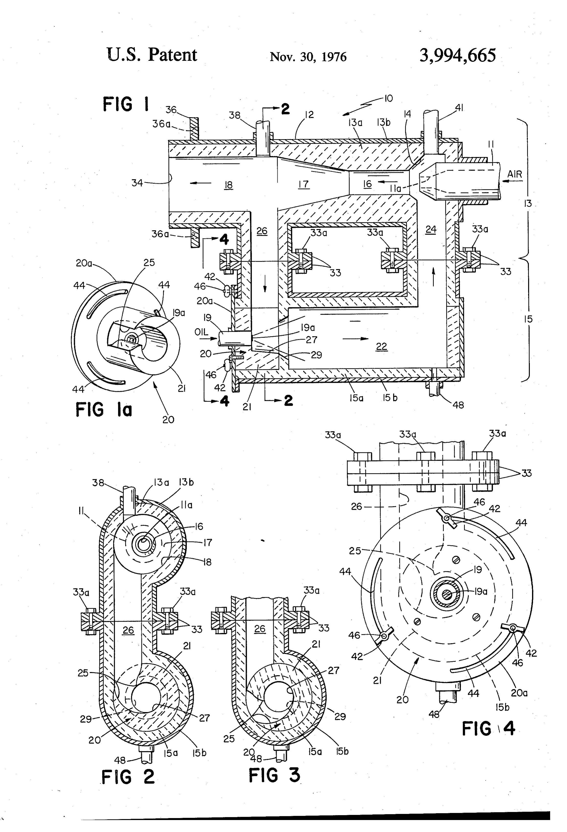
second passage effectively interconnecting the vaporiz ing chamber outlet with the combustion chamber inlet, generator FIG. 1a is an enlarged isometric view of the vortex the air inlet communicating with the second passage, used in the embodiment of FIG. 1; and a vortex generator in the housing at the interface of 65 FIG. 2 is a view through 2-2 of FIG. 1; the fuel inlet atomizer, the first passage, and the vapor FIG. 3 is a view of a portion of the embodiment of izing chamber inlet, the vortex generator being rotat FIG. 2, with the vortex generator blocking recircula able with respect to the housing between two positions, tion; and a first open position in which the vortex generator FIG. 4 is an enlarged view through 4-4 of FIG. 1.
Page 4scan →
DESCRIPTION OF THE PREFERRED near the vaporizing chamber outlet, will remove such fuel.
EMBODIMENT Air inlet 11, upon entering suction chamber 14, ter FIG. 1 shows burner 10, comprising housing 12, air minates with nozzle 11a. Air under pressure enters inlet 11, suction chamber 14, cylindrical mixing cham suction chamber 14 through nozzle 11a. This jet of ber 16, frustoconical diffuser 17, cylindrical combus incoming air creates in passage 24 a suction, which tion chamber 18, oil inlet nozzle 19, vortex generator draws the gaseous contents of vaporizing chamber 22 20, cylindrical vaporizing chamber 22, and cylindrical (4 inches in diameter) through passage 24 (2 inches in passages 24 and 26, passage 24 interconnecting vapor O diameter) into suction chamber 14. Inlet 1 I can be izing chamber 22 with air inlet 11 and suction chamber removed from burner 10 by removal of end plate 40. 14, and passage 26 interconnecting combustion cham Operation in the start-up and full-running modes will ber 18 with vortex generator 20 and vaporizing cham now be described. In start-up, air under pressure is ber 22. Passages 24 and 26, Vortex generator 20, and admitted into burner 10 through inlet 11. A pilot light vaporizing chamber 22 together provide a recirculation 5 is permitted to communicate with combustion chamber path, as will be explained in more detail below. 18 through tube 38. The air passes through suction Housing 12 comprises burner section 13 and recircu chamber 14, mixing chamber 16, diffuser 17, and com lation section 15, the sections being composed, respec bustion chamber 18. A portion of the air is drawn into tively, of inner refractories 13a and 15a, of 3000 F. passage 26 by the suction created by nozzle 11a and heat-resistant concrete, and outer metal piping 13b and 20 then into vortex generator 20. In generator 20, the air 15b. Sections 13 and 15 are held together by bolts 33a first enters throat 25 where it is accelerated by the between upper and lower flanges 33, the two sections constricted throat design, and passes into vortex cham together completing passages 24 and 26. Burner 10 is ber 27. Oil is then admitted in atomized form through mounted on a furnace, boiler or other heating recepta nozzle 19 and nozzle pin 19a into chamber 27 as a fine cle by means of flange 36 surrounding and spaced in 25 spray in a 50 cone, pin 19a determining the cone an ward from the combustion chamber outlet 34. Outlet gle. The air from throat 25 enters chamber 27 trans 34 is inserted into a hole in the furnace wall (not to versely to the direction of the oil spray and tangentially shown), and flange 36 bolted to the furnace wall thetheform spray cone. The air swirls through chamber 27 in of a vortex, and carries the oil mist out through flange holes 36a. Tube 38 permits a pilot light through chamber guide 29 into vaporizing chamber 22. to communicate with combustion chamber 18 at 30 burner start-up. Section 15 can be demounted from created by nozzle 11a ininpassage
The swirling air assists vaporizing the oil. Suction 24 draws the air-oil section 13 by removal of bolts 33a from flanges 33, if mixture through vaporizing chamber prolonged use of gas fuel is desired, making section 15 passage 24, into the flow of air from22,nozzle up through unnecessary.
suction chamber 14, through mixing
Passage 26 (2 inches in diameter), connected to where further mixing occurs, into diffuser 17, where chamber 16, combustion chamber 18 (inner diameter 3% inches), velocity head is converted into pressure head, and into carries hot, burned gases from chamber 18 to vortex combustion chamber 18, where the mixture is ignited generator 20. Vortex generator 20 (FIG. 1a) comprises by the pilot light in tube 38. The pilot light is shut off cylindrical refractory body 21 connected to end plate after ignition. Combustion occurs in chamber 18, dif 20a and containing constricted throat 25 and frusto 40 fuser 17 providing flame stabilization. conical vortex chamber 27. Throat 25 extends from In full operation, part of the gaseous products of passage 26, and is connected to chamber 27 trans combustion leaves burner 10 through outlet 34, but versely to the chamber axis, the lower portion of throat part is drawn into passage 26 by the suction created by 25 being curved to intersect chamber 27 tangentially nozzle 11a. These hot combustion gases enter vortex thereto (FIG. 2). Separate frustoconical chamber guide 45 generator 20, passing through throat 25, where they are 29 is fixed in section 15 between vortex generator 20 accelerated into vortex chamber 27. The hot gases and vaporizing chamber 22, is flared more than cham whirl in the form of a vortex around the cone of oil ber 27, and has an imaginary vertex angle of 50. Oil mist, as did the recirculating air in start-up, and vapor inlet nozzle 19 carries liquid fuel from an oil source ize the oil, preventing the oil from condensing on the through openings in end plate 20a and body 21 into 50 walls of vortex chamber 27 or vaporizing chamber 22. vortex chamber 27. Nozzle pin 19a atomizes the liquid This hot gas-oil vortex passes out of chamber 27 fuel into a fine spray in the form of a cone having a 50 through guide 29 into vaporizing chamber 22, where vertex angle projecting into chamber 27. Hot gases Vaporization of the oil by the hot gases continues. from combustion chamber 18 coming through passage Chamber 22 is kept below the temperature required to 26 and throat 25 are accelerated and swirl tangentially 55 crack the hydrocarbon fuel (usually 900 F.), because into a vortex about the oil spray cone in chamber 27. the heat required to vaporize the liquid fuel comes The term “vortex' as used throughout this application, from the hot gases, leaving them cooler, though cham when referring to gases, means not simply a swirling ber 22 stays above the fuel vaporization temperature motion of the gases but a tangential acceleration of the (usually 600°F.). Suction created by nozzle 11a draws gases to provide an accelerated swirling motion. Vortex 60 the hot gas-vaporized oil mixture from chamber 22 generator 20 can be removed as a unit from burner 10 through passage 24 and suction chamber 14 into mix by removal of end plate 20a, plate 20a being secured to ing chamber 16, where the mixture is further mixed piping 15b along flanged portions of both by wing nuts with the jet of incoming air. The hot gas-oil-air mixture 42 secured to studs 46 protruding from the flanged then passes through diffuser 17 to be burned in cham portion of piping 15b. The structure and operation of 65 ber 18. Combustion occurs with a blue flame, and is vortex generator 20 to cut off recirculation when gase quiet and Smoke-free. Fuel consumption is variable, ous fuel is used will be described below. Should con with a turndown range (the ratio of maximum fuel rate densation of fuel occur, drainage nipple 48, positioned in gph to minimum fuel rate in gph) of 4.5:1 and blue 5 flame operation throughout. One simply adjusts the in the United States and both entitled "Recirculating amount of spray through nozzle 19 and air through Burner", are hereby incorporated herein by reference. inlet 11 to obtain the desired rate of consumption Other embodiments are within the following claims. within the permitted range. Fuel and air inputs can be . 5. ... What is claimed is:
1. A recirculating burner for burning a vaporizable stoichiometric, though excess air can vary up to at least liquid fuel comprising:
200 percent. a housing,
In full operation as above described, passages 24 and a combustion chamber in said housing, 26, vortex generator 20 and vaporizing chamber 22 are said combustion chamber having an inlet and an all wide enough to provide, in conjunction with air inlet () outlet, 11 (which, with suction chamber 14, mixing chamber a vaporizing chamber in said housing, 16, and diffuser 17, acts as a jet pump), a percent recir is said vaporizing chamber having an inlet and an culation sufficient to maintain, blue-flame combustion, outlet, which, with no excess input air, would be at least 50 percent under standard conditions, i.e., l atmosphere 5 anpressure air inlet, in said housing for directing air under into said combustion chamber, of pressure and 70 F., where percent recirculation, R, a fuel inlet atomizer in said housing, adjacent to said is defined as follows: vaporizing chamber inlet, for atomizing vaporiz able liquid fuel from a source of the same and
R = - standard cfm of recirculated combustion products X 100.
standard cfm of stoichiometric input air directing said fuel into said vaporizing chamber, 20 a gaseous fuel inlet in said housing for feeding gase ous fuel from a source of the same into said com
The inner width of these parts, which together define bustion chamber, the recirculation path, is large enough to lower the a first passage interconnecting said combustion pressure drop caused by nozzle 11a and sustain this chamber toward said combustion chamber outlet large amount of recirculation flow. 25 with said vaporizing chamber inlet, When thc desired fuel is a gas, such as natural gas, said first passage being arranged to receive hot recirculation is unnecessary, since the fuel does not combustion gases from said combustion cham nced to be vaporized. Vortex generator 20 is rotatable, ber, with respect to recirculation section 15, about the axis 30 a second passage effectively interconnecting said of vortex chamber 27. The three wing nuts 42 connect vaporizing chamber outlet with said combustion end plate 20a to piping 15b by being threaded onto chamber inlet, studs 46 protruding through arcuate slots 44 (FIG. 4) said air inlet communicating with said second pas in end plate 20a from the flanged end portion of piping sage, and - 15b. In FIGS. 1, 2, and 4 vortex generator 20 is shown a vortex generator in said housing at the interface of in the open position, permitting recirculation of hot 35 said fuel inlet atomizer, said first passage, and said combustion gases as above described. In this open posi vaporizing chamber inlet, tion each wing nut 42 is tightened onto its respective said vortex generator being rotatable with respect stud 46 at one end of each slot 44 (FIG. 4). When wing to said housing between two positions, nuts 42 are loosened, end plate 20a is rotated counter 40 a first open position in which said vortex genera clockwise to bring the opposite end of each slot 44 tor receives hot combustion gases from said against its respective stud 46, thereby rotating throat first passage and swirls them into a vortex, into 25 wholly out of alignment with passage 26, interposing which vortex said fuel inlet atomizer is adapted body 21 into the path of passage 26, blocking flow to direct atomized liquid fuel, for vaporization through this passage, for use of the burner in the gas 45 of said fuel by said hot gases in said vortex generator and vaporizing chamber, and said mode (FIG. 3). Nuts 42 are tightened to maintain this first passage, said vortex generator, said vapor blocking position. Gaseous fuel is then admitted izing chamber, and said second passage to through inlet 41 into suction chamber 14 tangentially gether define a recirculation path for hot com to air entering through nozzle 11a. For prolonged use bustion gases from said combustion chamber in the gas mode, recirculation section 15 can be de 50 to said vaporizing chamber and back to said mounted and removed from burner 10. In that case, the combustion chamber, where vaporized fuel is upper halves of passages 24 and 26 are blocked by burned with air from said air inlet, and covers bolted to upper flanges 33. second closed position in which said vortex Modifications include a vertex angle from 30 to 50 generator blocks the flow of hot combustion for the oil spray cone. 55 gases from said first passage to said vaporizing Vaporizing the fuel in a separate vaporizing chamber chamber, thereby blocking said recirculation by the heat of recirculating hot gases before the atom path, and said gaseous fuel inlet feeds gaseous ized fuel reaches a wall was the invention of Alex F. fuel into said combustion chamber for burning Wormser. Spraying atomized liquid fuel in the same therein with air from said air inlet. general direction as the flow of recirculating hot gases 60 2. The burner of claim 1 wherein said vortex genera and into that flow, and use of a vortex generator be tor has a cylindrical body and said fuel inlet atomizer tween the combustion chamber and the vaporizing includes a nozzle, chamber for swirling hot combustion gases into a vor said body contains a throat and a generally tubular tex into which atomized liquid fuel is introduced, for 65 vortex chamber extending axially within said body, vaporization of the fuel, were the invention of Andrew said body being rotatable about its axis between J. Syska. The contents of the Wormser application, said two positions, filed Aug. 22, 1975, Ser. No. 606,841, and the Syska said fuel inlet atomizer is connected to one end of application, filed Sept. 4, 1975, Ser. No. 610,250, both said vortex chamber, 6 said vaporizing chamber inlet is connected to the selectively rotated with respect to said housing, other end of said vortex chamber, thereby to rotate said body between said first and said throat is directed into said vortex chamber tan second positions.
gentially of said chamber, and 4. The burner of claim 3 wherein said vortex cham in said first open position, said throat interconnects 5 ber is frustoconical, the widest portion of said chamber said first passage and said vortex chamber along being at the end of said chamber connected to said the wall of said vortex chamber between the ends vaporizing chamber inlet.
of said chamber, and said nozzle produces agen 5. The burner of claim 2 wherein said gaseous fuel erally conical spray of atomized liquid fuel, 10 inlet enters said housing tangentially to said air inlet. whereby in said first open position said hot com 6. A recirculating liquid fuel burner which comprises: bustion gases are accelerated through said a combustion chamber, throat to form said vortex in said vortex cham a vaporization chamber, ber, and said vortex swirls about said conical a first passage connecting a downstream portion of spray of fuel, providing vaporization thereof 5 said combustion chamber with said vaporization before said fuel can hit a wall, and chamber, in said second closed position, said body blocks a second passage connecting a downstream portion flow of said hot combustion gases from said first of said vaporization chamber with an upstream passage to said vaporizing chamber. portion of said combustion chamber, 3. The burner of claim 2 wherein said vortex genera fuel delivery means to discharge fuel at the junction tor includes an end plate connected to the end of said of said first passage and said vaporization chamber, body at which said fuel inlet atomizer is connected, for air delivery suction means to cause recirculation common rotation with said body, said end plate and said body each have an opening from said combustion chamber through said first permitting said fuel inlet atomizer to pass there 25 passage, said vaporization chamber, and said sec through into said vortex chamber, ond passage, and said end plate has a plurality of arcuate slots therein, a vortex generator rotatably mounted at the junction said housing carries a plurality of fasteners for fasten of said first passage and said vaporization chamber, ing said end plate to said housing through said slots, whereby said vortex generator may be selectively said fasteners and said slots cooperating to provide 30 rotated betweensk an kopen and a closed position. adjustability, whereby said end plate may be . . k. k, k
Provenance
- Collection
- Patents citing this work
- Pages
- 6
- Method
- pdftotext (the PDF's own text layer) + pdftoppm 300dpi page scans
- Patent office record
- patents.google.com →
- Source
- Google Patents citing-documents table
- Assignee
- Consolidated Natural Gas Service Co., Inc.
- Published
- 1976-11-30
- Transcribed from
- patentimages.storage.googleapis.com →