

patent · US3063814A
Tubular furnace
13 November 1962
Text
Drawings
Page 1drawing sheetscan →
Page 2scan →
United States Patent Office Patented Nov.3,063,814
3,063,814 tion in furnacing to give short flame length (i.e., about
TUBULAR FURNACE one foot for gaseous fuels and about three feet for the James H. Shapleigh, Wilmington, Del, assignor to Her heavier liquid fuels); the lack of appreciation of the cues Powder Company, Wilmington, Del, a corpora advantages of short flames and their relationship to phys tion of Delaware ical factors important to economical operation; the dam Filed July 27, 1959, Ser. No. 829,576 age to tube metal due to impingement of flame or ex 3 Claims. (Cl., 23-277) tremely hot combustion gases; the intermittent detrimental This invention relates to tubular furnaces and more breaking and reforming of metal oxide films on reaction particularly to improved apparatus and method for more andtubes by presence of atmospheres alternately oxidizing efficient and economical treatment of fluid reactants in reducing, and the lowering of the strength of such tubular furnaces. films; the improper interference of combustion gas from In recent years the tube type furnaces, wherein thin two ance burners which promotes tube hot spots; the appear of spots and deposits on reaction tubes from the im walled metallic reaction tubes are passed through a re pingement of combustion gas streams from oil fired fractory heating chamber and externally heated by means burners, partly related to vanadium in the oil and low of combustion gases, have become very popular particu fusion point larly in the production of hydrogen and various olefins apart on theash; uneven tube temperatures at points 180 tube causing permanent tube deterioration;
from fluid hydrocarbons. Despite the wide use of such damage to the internal form of the metal and structure; furnaces and a great deal of development directed to their tube blistering and bloating; difficulty of control of lumi improvement, these furnaces are still characterized by 20 nous flames; and improper application and control of tube several disadvantages, the obviation of which would be tension.
most beneficial, particularly to the hydrocarbon reform In present tubular designs, one of the most popular of
Reaction tubes employed in tubular furnaces are gen reactionis tubes which disclosed in U.S. Reissue 21,521, one or more are suspended through the central portion erally elongated alloy tubes such as 310 metal ranging 25 of a heating chamber and gases of combustion are intro from 4 to 10 inches in diameter and having a tube wall duced into the chamber to transfer heat by convection and thickness in the neighborhood of 346 to 5/8 inch. In the radiation currently employed furnaces larger heating chambers are walls. Theto furnace both the tubes and the refractory furnace chamber walls then radiate the heat employed than would be desirable from the standpoint of thus received to the tubes. The burners spaced vertically economy in construction. 30 introduce combustion envelopes or streams between the Many furnaces are fired with gaseous fuels rather than tubes and the adjacent furnace wall or else between rows liquid fuels even in geographic locations where the liquid of tubes according to the number and spacing of the tubes fuels are cheaper. In locations where gaseous fuels are in the particular furnace cell. It has theretofore been prohibitively expensive, the installation of tubular fur found necessary to leave a considerable space between the naces has been retarded by fear of detrimental effects on tubes and furnace wall and/or between the rows of tubes metal tubes when operated at the high temperature gen where firing is performed between the tubes, thereby erated by liquid fuels. While problems exist in tubular necessitating an undesirably large firing chamber. Al furnaces employing gaseous fuels when attempt is made though this particular to attain the full potential of high metal temperatures, worldwide basis and hasarrangement has been used on a these problems are greatly increased when liquid fuels are 40 tory furnace, inadequaciesbeen considered a very satisfac employed. Liquid fuel has been employed in tubular it is desired to increase tubearecapacity, nonetheless present when to employ larger furnaces in both the United States and Europe but these installations are still lacking in the attainment of advan tubes, to use tubes under pressure, to employ intensified and more critical reaction Zone conditions and in general tages art.
which have been long sought in the tubular furnace to pass into improved fields of operation (particularly with Criticism has been leveled at the tube-type furnace to liquid hydrocarbon firing) and to the use of liquid feed the effect that it is difficult to obtain a high heat input to gaseous, highly stock or unsaturated feedstock instead of the usual paraffinic feedstock.
the tubes because, to avoid physical damage to the metal, In prior art tubular furnaces the walls of the heating temperatures must be below 1600 F. Actually, this chamber have had the sole purpose of forming a refrac criticism is completely unjustified and it has been demon tory Walled enclosure in the simplest and least expensive strated, particularly with gas firing, that with proper fur manner consistent nacing techniques considerably higher temperatures may The furnace walls with the necessary structural strength. have been of uniform thickness, the be employed. Nevertheless, even those skilled in this actual thickness being varied according to well-known advanced state of tubular furnacing realize that there ex tables of heat loss to prevent external radiation insofar as ists a large field of improvement still to be obtained which 55 is economically feasible. The furnaces have been rec would greatly broaden the scope of use of tubular fur ittangular or round and have been about 25 feet high be naces and constitute great improvement over the present tween arch and hearth. The burners in such furnaces state of development in this field. For example, it would be highly desirable to obtain one or more of the following have been mounted in burner blocks and while the burner nozzles have not been aimed directly at the tubes in the improvements: gain in capacity per unit of investment 60 better designs, the incompletely oxidized gas envelopes which would approach current refinery capacities in terms have extended into the chambers to produce fluctuating of barrels per day; use in high temperature reactions gen reducing and oxidizing atmospheres highly conducive to erally thought to be out of the field of tubular furnace tube damage. - practice; a marked reduction in the quantity of catalyst The problem of economically introducing heat into necessary per unit of output from a catalytic process; an 65 reaction tubes is further complicated by the current belief increased use of heavy liquid as process feedstock; and broader use of pressures above atmospheric and particu in the art that the reaction tubes must be widely spaced from each other in order to effect high percentage ab larly above 100 p.s. i. In the path of obtaining such Sorption of radiant heat and to allow sufficient circula desired results, however, stand one or more of the follow tion of combustion gases therebetween to prevent uneven ing hindrances which are applicable to both the use of 70 tube temperature. Such uneven heating on opposite gaseous or liquid fuel in the firing of the present tubular sides of the tube may cause cracking. Moreover, such furnaces; difficulty in attaining and controlling combus cracks cause pressurized streams of burning reactants 3 to jet into the combustion chamber and damage closely wardly in a state of compression. Thus, it is common adjacent tubes. Thus, the chambers of tubular furnaces in current industrial practice to have manifold tubes currently employed have been further enlarged due to suspended by means of springs from above the furnace this wide tube spacing and the necessity for spacing the arch in states of downward tension substantially less outermost tubes far enough from the furnace chamber than that of a fully suspended tube in downward tension wall to prevent detrimental flame impingement. under its own weight. In practice, however, these spring The supporting of the reaction tubes in the tubular mounts have been found to be inadequate in many ways. furnace has also presented many difficult problems to Primarily there is insufficient control of tension on the the art. Some of the shortcomings of tubular furnaces individual tube and warping has resulted. Moreover, in some high temperature reactions are due to the effect 10 the creep of the tube is not under positive control and excessive changes in length occur. Tube life is thereby on tube metal of the temperatures necessary to the de sired reactions. Metal temperatures within the appara shortened.
In accordance with my copending application Ser. No.
tus, particularly in the production of hydrogen either by reforming methane or by cracking of liquid hydro 476,201, now Patent No. 2,914,386, it has been dis carbons, may range from a black heat at the furnace covered that one or more of the difficulties above dis arch to as high as 2000 to 2400 F. at the furnace cussed may be obviated by a new furnace design whereby hearth. Within this range, and particularly at tempera a new and greatly broadened scope of use is opened up tures between 1100 to 1700' F., serious weakening to tubular furnaces.
effects arise during service due to carbide precipitation According to my new furnace design there is pro inherent in the otherwise desirable stainless steels. 20 vided a tubular reaction furnace having in combination Moreover, these highly heated reaction tubes, generally a shell comprising a refractory walled heating chamber employed in lengths of 20 to 30 feet, undergo expansion having spaced portions of greater thickness than the of as much as 5 to 7 inches when heated to these high intermediate portions, vertically disposed metallic reac metal temperatures. In most furnace designs the tubes tion tubes passing through the heating chamber and normally pass through both the arch and the hearth and spaced from the chamber walls, and fluid hydrocarbon are subject to binding stresses caused by temperature burners to furnish hot combustion gas to the heating effects. In addition to elongation, there is a tendency chamber mounted in elongated tunnels formed in the for the tubes to bloat due to internal pressure during thicker portions of the chamber walls, said tunnels being operation and to low creep strengths at high temperature. located at a plurality of vertical levels and so disposed The weakening effects caused by these changes have in 30 in the chamber wall that the extension of a straight line the past been partially offset by supporting the reaction drawn from the burner nozzle to a point on the end of tubes from above in order that the weight of the tube, the innermost wall of the tunnel in the horizontal axial together with the weight of manifolding below the fur plane will pass between the reaction tubes and the ad nace hearth, plus the weight of the catalyst, Will exert jacent chamber wall. Although the shell may have any a downward pull on the tube wall, thus placing the tubes desired outer configuration, it will preferably be sub under axial tension. Such an arrangement constitutes a stantially rectilinear in cross-sectional exterior con considerable improvement over prior practices where the figuration. In such apparatus the thickness of the portion of tubes were anchored below the furnace and where the effluent was removed from the top of the tubes rather 40 the chamber walls containing the burner tunnels will be than from base points below the furnace. However, -controlled by the particular reaction for which the fur the use of downwardly applied tension in suspended tubes nace is constructed and the type of fuel employed. It has in turn worked a very undesirable temperature limi is desired to retain as much as possible of the combustion tation since, as the tension is increased for a given tube envelope from the burners in the burner tunnels. By of given wall thickness, the upper limit of temperature use of the burner tunnel, the hot combustion gas streams which can be employed must be correspondingly de 45 into the heating chamber and out of direct contact with creased to prevent structural failure of the tube itself. the tubes to prevent detrimental flame impingement and This difficulty can be readily appreciated when it is to protect the tube from damage due to fluctuating con realized that a reaction tube made of type 310 metal, ditions. Even when employing gas as a fuel, it is a 30 feet in length and 8 inches in diameter with a wall difficult matter to consistently retain the entire combus thickness of about A inch will normally weight about 50 tion flame within a tunnel. When employing oil as a 800 pounds. Depending upon the specific catalytic re fuel, it is impossible to retain all of the flame within action being conducted, this tube may contain from about a tunnel of any practicallength. However, with either 600 to 1200 pounds of catalyst. Thus, when the weight fuel the flame which does emit into the heating chamber of the manifolding below the furnace is added to the is directionalized and controlled. With either gas or weight of tube and catalyst, it will be seen that a force 55 oil firing, therefore, the reaction tubes may be disposed of about 2000 pounds is being directed downwardly closer to the chamber walls and in a chamber of the along the tube. In addition there will be a downward in same size more reaction tubes can be employed than thrust on the bottom of the tube enclosure related to furnace designs heretofore employed, thus greatly in the pressure within the tube. These various effects re creasing the efficiency and economy of the furnacing sult in a tube tension which is normally highest at the 60 operation.
bottom of the tube where the greatest temperatures will Now in accordance with the present invention, it has normally be applied and therefore, where the tube will been discovered that additional improvement is obtained have its lowest creep strength. Thus, the temperature by a recirculation of combustion gas from the combus must be lowered to a point corresponding to the strength tion chamber to at least one burner tunnel through at of the tube at a sacrifice of reaction efficiencies through 65 least one duct tunnel positioned in the wall of the com put or both. bustion chamber. With this arrangement in which a por Further, in multiple tube furnaces with tubes joined in tion of the hot combustion gas is introduced into a cooler a common manifold at their base below the hearth, the Zone of a newly fired burner stream, it has been found separate tubes undergo unequal expansion. This un that many advantages accrue. For example, because of equal expansion creates a condition wherein the floating 70 the intermixing of the recirculating combustion gas with position of the manifold is determined by tubes in a the newly fired burner stream, there is the introduction of oxygen contained in the recirculating combustion gas different state of tension, the tube of highest temperature normally being in the state of least downward tension. into the firing stream which causes a quicker ignition and In fact, under extreme conditions a tube might ap a more complete combustion of the fresh fuel contributed proach zero downward tension and actually expand up 75 to by the higher temperature recirculating gas on the 4 initially lower temperature fresh stream burner combus the furnace hearth to support members, manifolding, a tion. The combined effects result in a shorter flame and quench tank, a secondary furnace or other process equip a more favorable completion of combustion prior to for ment and tension will be applied in the upward direction mation of the combustion envelope within the furnace by means disposed above the furnace arch. Such means proper. When oil is the fuel, the duct tunnel recirculation 5 may be manually or automatically controlled to exert the of gas causes the oil to gasify and mix faster with oxygen desired amount of tension on the tubes and thus permit within the burner tunnel, thereby accelerating combustion the use of higher temperatures which in turn will derive within said tunnel. Furthermore, a principal advantage of a multiple fired furnace resides in its control to main the highest efficiencies from the metals employed. Thus, where a tensile force of as much as 2000 pounds has been tain a desired temperature gradient. The gradient is, of 10 employed in prior art designs where the tubes are sus course, established by control at the firing "points.”
Ideally, a smooth controlled transition to establish the instance, a 200though pended even it is only necessary to employ, for pound tension to minimize binding, bloat gradient is most desirable rather than a gradient estab-. ing, or warping, it is possible in accordance with the pres lished by multiple firing "points.” The present invention ent invention to apply exactly the amount of tension de tends to establish such a smooth controlled transition since there is produced a mixing cycle between the com sirable tions.
and thus remove undesirable temperature limita bustion chamber gas at lower temperature and the com bustion gas which upon completion of combustion is at forinapplying terms of process, the invention relates to a process higher temperature which to an extent produces a moder tubes passing heat to vertically disposed metallic reaction through the refractory walled heating cham ate tempering of the combustion gas before it issues from 20 ber of a tubular furnace which comprises, at a plurality the burner tunnel into the combustion chamber. of vertical levels introducing streams of newly fired gas More explicitly, the present invention comprises a tubul into lar reaction furnace having in combination a heating to thethesurfaces heating chamber along paths obliquely disposed through which the streams emit and which chamber the walls thereof having spaced portions of greater thickness than the intermediate portions, at least 25 paths direct the streams between the tubes and the adja cent refractory wall, maintaining said streams out of con one vertically disposed reaction tube passing through the tact with the tube until substantially complete combustion heating chamber and spaced from the chamber Walls, a of the gas has occurred, continuously maintaining a plurality of vertically spaced burners to supply hot com blanket of the fully oxidized gas around the tubes to pro bustion gas to the heating chamber each of which is dis vide a continuous oxidizing atmosphere for the tubes and posed in an elongated burner tunnel within the spaced por 30 reintroducing a portion tions of greater thickness of the chamber walls, and at ally fired burner mixture,ofsaid this oxidized gas into the initi least one duct tunnel disposed subjacent to at least one of gas entering the chamberblanket at the diluting the streams interfaces formed burner tunnel having its ingress opening in communica between the blanket and streams and said blanket being tion with the interior of the heating chamber and having its egress opening in communication with the interior of continuously replenished from said diluted portion, and leading the combustion gases in the path between the said burner tunnel. The present invention also comprises tubes and chamber wall and in the blanket through the a method of treating fluid reactants in a tubular reaction chamber in substantially parallel relationship to heat the furnace heated by introducing hot combustion gas into the furnace from a plurality of vertically spaced burner tubes by convection and radiation from the gas and by radiation from the refractory wall. Preferably the com streams, the improvement which comprises withdrawing 40 bustion gases in their ultimate path will be led upward a portion of the combustion gas as such and introducing to exit adjacent the top of the furnace structure. it into a cooler zone of a newly fired burner stream. In employing the apparatus of the invention, new and As indicated, the furnace itself will preferably be square beneficial heat relationships or rectangular in cross-sectional external configuration. chamber. As the furnace areoperation set up within the furnace The internal cross-sectional configuration of the heating combustion gases are introduced into theis chamber initiated, hot chamber will preferably be either elliptical, octagonal or the burner tunnels and flow along the chamber wallfrom be circular. Thus, the portions of the chamber Wall adjacent tween the wall and the nearest tubes. As this gas comes the furnace corners will be thicker than the intermediate from the burner and begins to burn, reducing con portions. In this manner thickened portions may be eco ditions are present and continue to be present until com nomically provided adjacent the corners for the disposition 50 plete combustion is achieved. Then the gas, contains of the burner tunnels without the necessity of providing water and from about
Dutch oven type effects and without the necessity of pro on firing conditions and4 to about 9% oxygen depending location. Generally, the com viding a furnace wall of a uniform thickness Sufficient to bustion gas entering the duct tunnel or duct tunnels will accommodate adequate burner tunnels. Moreover, due be within the temperature range of about 2600 F. to the thickness of the corner portions of the structure, 5 5 maximum and a minimum temperature of about 1200 F. regions of higher heat capacity are provided which add The quantity of recirculating gas per duct tunnel will be to the use and performance of the furnace. related to the inspiration and convection effect which in In one preferred embodiment of the invention the tubes turn are related respectively to the position, size and will be spaced from each other on centers of from 1/2 to shape of duct tunnel openings and to the temperature 24 tube diameters. It has been discovered that when 60 difference between the intake of the duct tunnel and the care is taken to avoid detrimental flame impingement, and point where the combustion gas and burner tunnel gas particularly in the improved furnace design of the inven mix. In the invention, it is desirable to effect as nearly tion utilizing the duct tunnels, adequate heat input to the complete combustion in the burner tunnels as possible. tubes can be obtained with this relatively close tube Spac In any event, even if complete combustion has not oc ing which has heretofore been deemed undesirable by the 65 curred in the tunnel, the directionalized flow along the art. Thus, in a chamber of given size, the closer Spacing wall allows complete combustion to take place before of tubes provides more space between the tubes and the tube contact. This gas, now an oxidizing gas, proceeds chamber walls and further enhances the controlled pro upwardly around the chamber wall, with a portion tective combustion gas flow and reintroduction thereof diffusing to the newly fired burner stream characterizing the inven 70 circulatinginwardly into the center of the chamber and tion. Alternatively, where this additional protection is outwardly and passingtubes about the and with a portion circulating through the duct tunnels for re unnecessary, chamber size can be reduced with corre entry with the newly fired burner streams. As operations sponding economies. continue, this centrally disposed body of oxidizing gas In accordance with another preferred embodiment of continues to surround and bathe the tubes in a con the invention, the reaction tubes will be anchored below 75 tinuously oxidizing atmosphere. As the relatively hotter
Page 5scan →
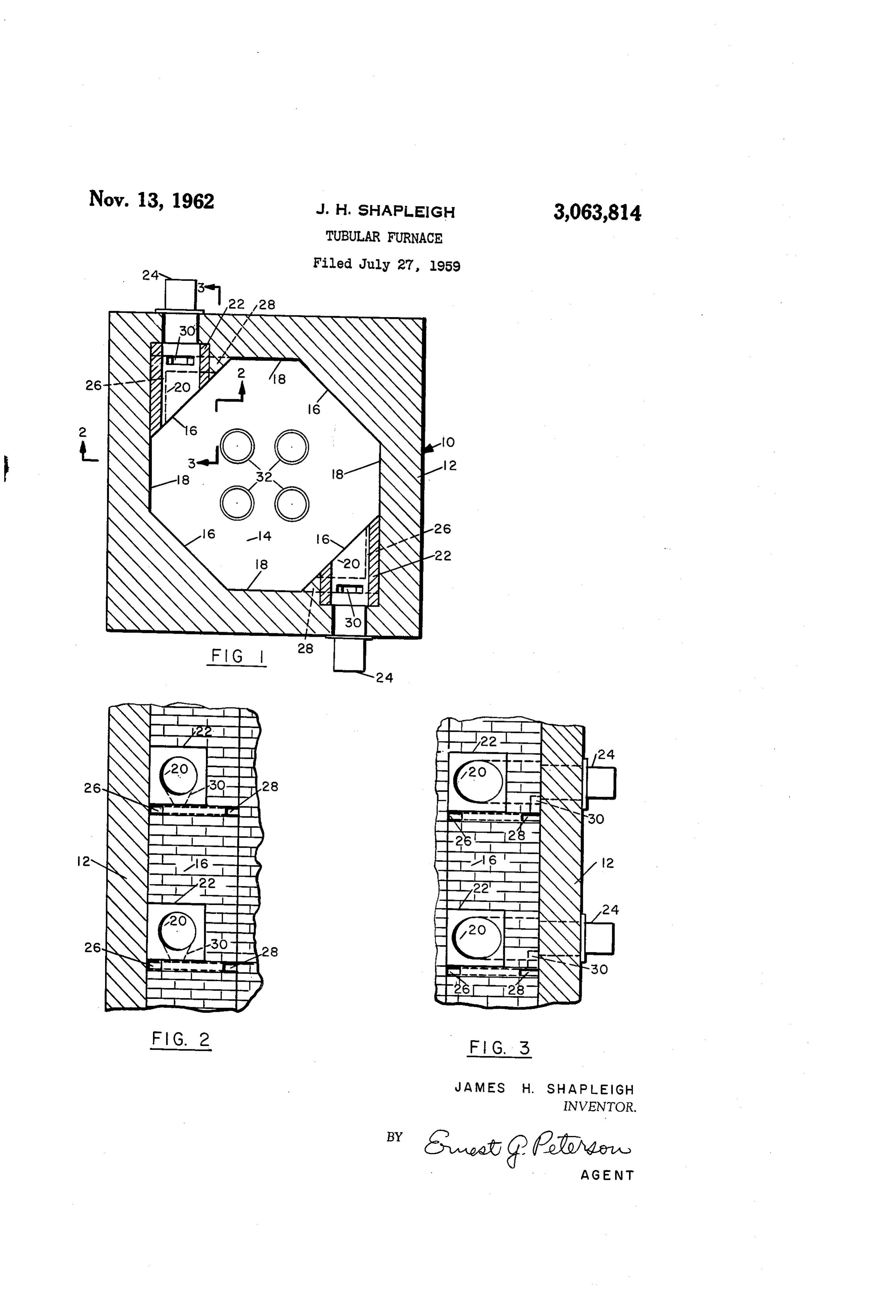
7 trated has a refractory wall 12. The external cross fresh burner gas emits from the tunnels, usually at a Sectional plan configuration of the furnace is substantially temperature of about 3500 F., it flows peripherally around the outer portion of the chamber. Even when Square while the internal cross-sectional plan configuration combustion is not complete at the mouth of the tunnel of the heating chamber Íá is substantially octagonal. Four of the sides or thickened portions 16 of the octagon and reducing conditions exist at that point, the tubes are forming the walls of the heating chamber 14 are of sub protected by the inner body of oxidizing gas. The inner stantial thickness while the other four intermediate sides fringe of the gas stream emitting from the tunnels and or thinner portions 8 are of conventional thickness. circling around the chamber is constantly diluted by the relatively cooler oxidizing gas and recycle thereof through Elongated burner tunnels 20 with refractory housings 22 the duct tunnels and diffuses inwardly to become part of 0. are disposed in the thickened portions 16 and a fluid the inner protective columnar body, a corresponding por hydrocarbon tunnels and burner 24 is located at each of the burner fires therein. A duct tunnel 26 and a duct tion of which exits from the flue with the other gas. tunnel 28 is disposed subadjacent to each of the burner - In a single cell furnace it is preferred that the com bustion gas streams all flow into the chamber in the same tunnels 29. These duct tunnels have their ingress open ings in juxtaposition with the transition intersection of the direction. In this manner, smoothest flow of gas is ob thickened wall portions 16 and the thinner wall portions tained and the stream from each burner joins the uni š8 of the combustion chamber and have a common di directional flow. However, this arrangement is not al vergent egreSS opening 30 in direct communication with ways practical, especially in some multiple cell furnaces the interior of the burner tunnel 20 with the egress open where it may be desirable to fire from only two faces.
In multiple cell furnaces, for example, it may be de 20 ing entering the burner tunnel in the vicinity of the hot flame area of the burner. A plurality of reaction tubes sirable to fire from two faces at each level with gas flow 32 pass vertically downwardly through the chamber 14 being in opposite directions at each level. While such flow causes turbulence and some reduction in efficiency and are spaced from each other on centers of approxi mately i/2 tube diameters. In the structure shown, two of the duct tunnels, the gas stream from each burner be comes completely oxidized in its travel from the burner burners are disposed at each horizontal level, however, one, two, three or four burners per level may be employed tunnel to the far side of the chamber and the turbulence as desired. In operation of the furnace, fluid hydrocarbon and minor reduction in efficiency is not detrimental. is introduced into the burners and ignited. The com The use of burner tunnels and duct tunnels, the con trolled peripheral flow and the presence of the inner pro bustion gas streams are directionalized by the walls of tective body of relatively cooler oxidizing gas results in 30 the tunnel, so that the hot gases will pass between the tubes and the wall of the furnace without detrimental great advantages particularly in terms of metal tube life flame impingement on the tubes. The gases which diffuse and permissible temperatures. Not only is detrimental inwardly flame impingement eliminated, but of equal importance, convectionareandcompletely radiation.
oxidized and heat the tubes by
The refractory furnace walls the tubes in the furnace are not exposed to the metal damaging fluctuation between oxidizing and reducing coil the tunnels and radiate heat to theflow are highly heated by the peripheral of hot gas from tubes. Due to the ditions which is present in the prior art apparatus. There oblique surfaces involved, the gases from the burners are fore, the tubes are immediately coated with a thin, per conducted manent, protective film of metal oxide which is Smooth, The gases smoothly around the tubes in a spiral path. diffusing inwardly to form the protective ductile and elastic. This film is fiuid impervious and pre vents or minimizes detrimental tube damage resulting 40 blanket of fully oxidized gas also move generally spirally about and between the tubes and continuously bathe the from vanadium and low fusing alkali sulfates present in tubes inan oxidizing atmosphere. Additionally, a por fuel oil. In prior furnaces, tube metal was liable to attack of varying degree of frequency first by an oxidizing tion of the oxidized gas passes into and through the duct atmosphere and later by a reducing atmosphere due to in tunnels and into the burner tunnel where it intermixes sufficient latitude against mechanical and human failure 45 with As the newly fired burner stream combustion products.
pointed out previously, this recirculation assists in a in control with the resulting scaling of metal causing de quicker ignition and more complete combustion of the creased tube life. fresh fuel which in combination results in a shorter flame Moreover, the method of heating in the apparatus of which, of course, is a highly desirable object of the inven the invention keeps the hottest gas close to the refractory tion. The total spent gases are withdrawn from a flue, not wall thus more efficiently heating the primary source of shown, at the top of the chamber and thus progress in an radiant heat to the tubes. If desired, oxygen or oxygen ascending path around the tubes. The eight angular in enriched air can be employed together with the hydro ternal Surfaces add to the efficiency of the radiation from carbon feed to generate hotter flame and hotter gases of the refractory walls of the furnace to the reaction tubes. combustion due to the new protection afforded to the in addition to these eight walls the portions of the burner tubes. Thus, substantially greater heat input can be 55 tunnel Walls which are obliquely extended also furnish obtained without tube damage. radiation Surfaces for the heating of the tubes. The introduction of gas into the chamber along a path More specifically, in accordance with the furnace design disposed obliquely to the furnace face from which the of this invention, with vertical disposition of burners in gas emits adds considerably to the efficiency of the the sidewalls thereof, there is an upward gradient of re furnace. Each portion of the longer, outer wall of the 60 fractory temperature and of combustion gases within the burner tunnels which extends beyond the end of the furnace. The amount of the gradient is flexible and re shorter inner wall of the tunnel becomes a highly heated lated to the conditions of operation of the furnace, said radiating surface which would otherwise be lost if the conditions being related to the performance taking place tunnel walls were of equal length. within the tubes being heated. For example, in practicing A preferred embodiment of the invention has been 65 the invention there is a draft gradient vertically within chosen for purposes of illustration and description and is the furnace varying from about 0.75 inch water to sub shown in the accompanying drawing wherein reference stantially Zero. Within the furnace therefore, and ver symbols refer to like parts wherever they occur: tically disposed therein, temperature differences as well as FIG. 1 is a sectional plan view of a single cell-tubular draft differences between levels exist. Accordingly, the furnace employing the principle of my invention; 70 temperature diference and the pressure diference are em FIG. 2 is a fragmentary elevational view taken along ployed in the natural circulation of the combustion gas line 2-2 of FIG. 1; and - from within the heating chamber to the burner tunnels, FIG. 3 is a fragmentary elevational view taken along all of which is carried out within the walls of the furnace line 3-3 of FIG, . itself. Here it will be appreciated that an additional ob With reference to the drawing, the furnace i0 illus 5. jective of the present invention is to employ combustion 6 gases from aore than one burner and at a substantial hollow squares or rectangles or in single or concentric connbustion envelope travel distance from the exit cf the circles and the like. The discovery that it is possible to burner tunnel whereby great assurance exists that the obtain completely satisfactory results by the cioser spacing coinbustion gas will be of an analysis which is a composite of the reaction tubes in accordance with the invention result from the multiplicity of burners which normally makes it possible to obtain the same throughput with a aSSures the presence of oxygen as furnaces are customarily smaier, less expensive furnace or to obtain greater fired. Furthermore, and with reference to the drawing, throughput with a furnace of the size currently employed the entrance point of the duct tunnel into the burner tunnel is from the under side whereby natural circulation butAshaving more tubes.
is independent and separate from the inspiration effect of O may beindicated, the apparatus and method of furnacing employed for any desired reaction which lends it the burner nozzle.
in designing a furnace in accordance with the inven self to tubular processing. However, greatest utility will tion, it is preferred that the wall thickness at the thinnest be found in the hydrocarbon field and particularly in the manufacture of hydrogen, and olefins and refining prod point be ef conventional thickness, that is, normally ino ucts. All of the normally employed feedstocks ranging less than about 12 to 14 inches in order to obtain the de sired heat capacity. It is at once apparent that burner 5 from methane through crude oils may be employed. In like manner the reforming and cracking catalyst employed tunnels of sufficient isngth cannot be had in a wall of by the art may be used in the catalytic reactions. this thickness. However, by employing the preferred octagonal, circular, or elliptical internal configuration of Since many modifications of the invention as disclosed the chamber, the corner portions of the furnace become will be apparent to those skilled in the tubular furnace thick enough for the formation of burner tunnels, desir 20 by art, it is intended that the invention shall be limited only the scope of the appended claims.
ably about three feet in length and duct tunnels, frcin This application is a continuation-in-part of my copend about two to about twelve feet in total length, with the vertical riser of the duct tunnel from about one to about ing application, Serial No. 476,201, filed December 20, ten feet. if desired, inapingement devices or baffles may 1954, now Patent No. 2,914,386, patented November 24, be employed within the burner tunnels to promote more ràpid combilistion. What I claim and desire to protect by Letters Patent is: AS indicated, in a furnace composed of a single cell as 1. in a tubular reaction furnace having a heating cham illustrated, firing may be effected from a single face, ber, the wallis thereof having spaced refractory Wall por from two, from three or from all four furnace faces. tions of greater thickness than the intermediate portions, Where two cr more adjacent cells form the furnace, 30 and having reaction tubes passing through the heating firing will desirably be effected from two or three faces chamber and spaced from the chamber walis, and hav per ceil. If four ceils are employed to compose the ing a plurality of vertically spaced burners to supply hot furnace, firing will advantageously occur from two faces combustion gas to the heating chamber, each of which of each cell. However, despite the number of cells or 35 is disposed in an elongated burner tunnel within the spaced the number of faces from which the furnace is fired, ad refractory walil portions of greater thickness to avoid di vantage is gained due to the relative freedom from flame rect impingement of the hot combustion gas from the or hot gas impingement as described. burners with the reaction tubes; the improvement com Whiie it is necessary that the inner boundary of the gas prising:
streams or envelopes emitting from the tunnels do not cut 40 (a) two duct tunnels horizontally disposed subjacent to the cross-sectional area of any of the tubes, the contacting each elongated burner tunnel and spaced therefrom of the Wail of the furnace directly adjacent the mouth of and disposed within the spaced refractory Wall por the tunnel is desirable to highly heat the primary radiating tion of a greater thickness, surfaces. (b) an ingress opening for each duct tunnel horizon AS previously indicated, the angular or curved faces of 45 tally spaced apart and in communication with the in the furnace opposite the mouth of the burner tunnels act terior of the heating chamber, and as deflecting faces and direct the extended ends of the (c) each said duct tunnel extending from its ingress combustion envelopes or streams around the periphery of opening to a common egress opening extending up the chamber. Thus, where the burners are all aimed in a wardly into the interior of each said elongated burner similar clockwise or counter-clockwise direction, the gas 50 tunnel to provide mixing means between the lower will flow smoothly about the furnace in a direction paral temperature combustion gas from the heating cham lel to the walls and also into the duct tunnels. This ar ber and the higher temperature combustion gas with rangement provides for minimum flow around individual in the burner tunnel to accelerate complete combus tubes and is preferred. As indicated, however, if turbu tion of the latter gas and to produce tempering of lence is desired it can be produced by opposed gas flow 55 the gases issuing from the burner tunnel. from burners aimed in opposite directions. While the 2. The tubular reaction furnace according to claim 1 burner tunnels shown are substantially horizontal, such in which the common egress opening is divergent with the disposition is not essential and the burners may be aimed maximum opening in direct communication with the in upwardly or downwardly as desired to obtain the desired terior of said burner tunnel.
gas behavior and temperature control within the chamber. 60 3. The tubular reaction furnace according to claim 1 In general, it is desired that the angle of flare of the burner in which the duct tunnels are in close vertical proximity tunnel be between about 20 and about 30 for best re to each burner tunnel.
sults, although for specific purposes greater or less flare may be desirable. The use of tunnels in general not only References Cited in the file of this patent provides for directionalization but broadens the group of 65 UNITED STATES PATENTS fuels which can be employed. For example, residues from thermal cracking of oils, asphaltics and the like may 2,430,101 Campbell et al. ---------- Nov. 4, 1942 be employed. 2,648,599 Throckmorton et al. ------ Aug. 11, 1953 With regard to tube spacing, it is not essential that 2,701,608 Johnson ----------------- Feb. 8, 1955 each tube be spaced from the adjacent tube by the same 2,867,270 Brzozowski -------------- Jan. 6, 1959 distance. Any desired tube arrangement may be em 70 2,914,386. Shepleigh -------------- Nov. 24, 1959 ployed, such as parallel rows, on rectangular centers, in 2,925,858 Reed ------------------ Feb. 23, 1960
Provenance
- Collection
- Patents citing this work
- Pages
- 6
- Method
- pdftotext (the PDF's own text layer) + pdftoppm 300dpi page scans
- Patent office record
- patents.google.com →
- Source
- Google Patents citing-documents table
- Assignee
- Hercules Powder Co Ltd
- Published
- 1962-11-13
- Transcribed from
- patentimages.storage.googleapis.com →