

patent · US4687880A
Tubular luminescence photovoltaic array
18 August 1987
Text
Page 1scan →
United States Patent (19)
Morris
54) tubular luminescence
Photovoltaic array
75 Inventor: Robert K. Morris, Colorado Springs,
Colo.
73 Assignee: The United States of America as represented by the Secretary of the
Air Force, Washington, D.C.
52 U.S.C. .................................................... 136/246 58. Field of Search ................................ 136/246, 259
Re. 30,584 4/1981 Russell ................................ 136/246 247,229 9/1981 Wheeler ................................ 362/32 2,506,625 5/1950 Woolley ..... ... 36/246 3,565,719 2/1971 Webb ......... ... 156/212 3,976,508 8/1976 Mlavsky ......... ... 136/246 3,990,914 11/1976 Weinstein et al. . ... 136/246 4,026,267 5/1977 Coleman ............................. 26/436 4,304,955 2/1981 Meckler .............................. 36/259 4,519,384 5/1985 Murtha ... ... 26/438 4,529,830 7/1985 Daniel ................................. 136/246
Other publications
Primary Examiner-Aaron Weisstuch
Attorney, Agent, or Firm-Bobby D. Scearce; Donald J. Singer
A photovoltaic solar cell system is provided which comprises a hollow light tube of substantially conven tional design of optically transparent material, generally square cross section and preselected length and width and having on the outer surfaces thereof longitudinally extending triangularly shaped grooves defining a plural ity of ridges having triangular cross section along the tube length, each ridge having a 90° apex angle and surfaces along its length defining a 45° angle with the inner surfaces of the tube; light concentrating optics are operatively connected to one end of the tube for direct ing light into the tube; and a plurality of solar cells are disposed on the outer surfaces of the tube in a rectangu lar array of size corresponding to tube size with the photoactive surfaces of the cells facing inwardly of the tube. The tube may be hermetically sealed and either evacuated or filled with inert gas in certain applications. 11 Claims, 9 Drawing Figures
Drawings
Page 2drawing sheetscan →
Page 3drawing sheetscan →
Page 4scan →
It is, therefore, a principal object of the invention to
TUBULAR LUMNESCENCE PHOTOVOLTAIC provide an improved photovoltaic system for conver ARRAY sion of sunlight to electrical power.
It is a further object of the invention to provide a
RIGHTS OF THE GOVERNMENT 5 modular photovoltaic system for remote mission appli cations.
The invention described herein may be manufactured It is a further object of the invention to provide a and used by or for the Government of the United States compact photovoltaic system for applications aboard for all governmental purposes without the payment of orbiting spacecraft.
any royalty. 10 It is yet another object of the invention to provide a BACKGROUND OF THE INVENTION photovoltaic system which is protected against radia tion damage and particle impact.
The present invention relates generally to photovol These and other objects of the invention will become taic systems for converting sunlight to electrical power, apparent as the detailed description of representative and more particularly to a novel system for directing 15 embodiments proceeds.
light onto enclosed photovoltaic arrays for electrical SUMMARY OF THE INVENTION power generation in remote applications:
Existing solar photovoltaic array structures are sub In accordance with the foregoing principles and ob stantially limited to planar (flat) arrays of large size to jects of the invention, a photovoltaic solar cell system is provide sufficiently high power for remote power ap 20 provided which comprises a hollow light tube of sub plications such as aboard orbiting spacecraft. Since Stantially cnventional design of optically transparent storage capacities of launch vehicles for space applica material, generally square cross section and preselected length and width and having on the outer surfaces tions are severely limited, flexible planar arrays were thereof developed consisting of photocells on flexible substrates 25 grooves longitudinally defining a extending triangularly shaped plurality of ridges having triangular which may be stored in rolled or folded condition and cross section along the tube length, selectively deployed after orbit insertion. The flexible 90° apex angle and surfaces along itseach ridge having a length defining a arrays suffer from distinct shortcomings in that large structures are required for high power systems, and 45° angle with the inner surfaces of the tube; light con inherent dynamic instability exists in the deployed array 30 centrating of the tube optics are operatively connected to one end for directing light into the tube; and a plural because of the light weight of materials used as sub ity of solar cells are disposed on the outer surfaces of the strates combined with substantial extension of the array tube in a rectangular array of size corresponding to tube for operation. Deployment mechanisms for flexible size, with the photoactive surfaces of the cells facing arrays can be complicated, expensive, and heavy. The inwardly of the tube. The tube may be hermetically large area subtended by the deployed flexible array 35 sealed and either evacuated or filled with inert gas in subjects the constituent solar cells to substantial meteor certain applications.
oid and particulate radiation impingement hazard which necessitates use of protective coverglasses for the DESCRIPTION OF THE DRAWINGS cells. The exposed surfaces also limit operating voltages The invention will be more clearly understood from due to space plasma interactions. Photovoltaic arrays 40 the following detailed description of representative having optics which concentrate sunlight onto individ embodiments thereof read in conjunction with the ac ual cells provide some protection from impact, but pres companying drawings wherein:
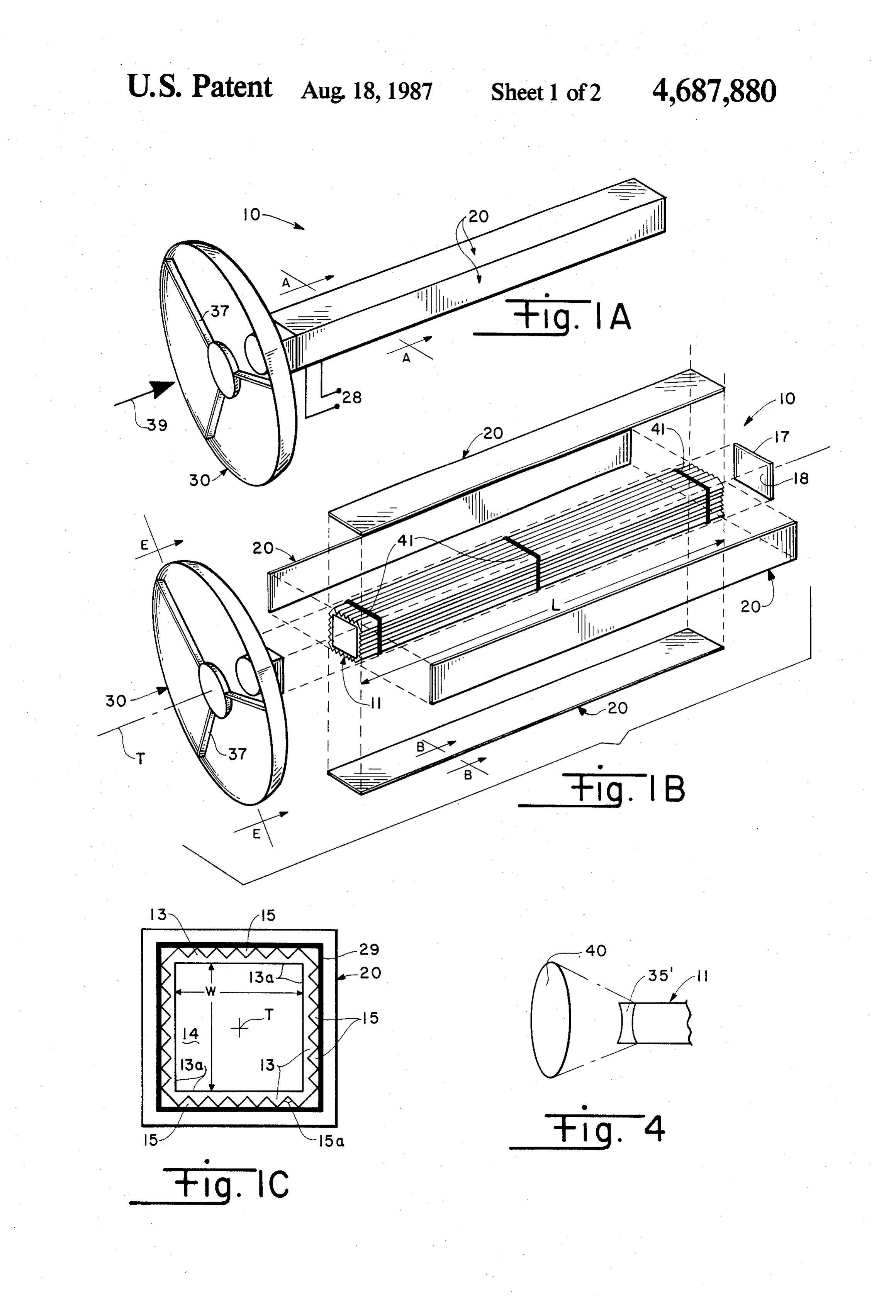
ent a weight penalty and require multiple complex and FIG. 1A is a schematic perspective view of a repre expensive optical collectors. sentative tubular luminescence photovoltaic array sys The present invention solves or substantially reduces 45 tem of the invention;
in critical importance the aforementioned shortcomings FIG. 1B is an exploded perspective view of the sys in existing photovoltaic systems by providing a photo tem of FIG 1A;
Voltaic power system particularly applicable for use in FIG. 1C is a sectional view along line A-A of FIG. providing electrical power to systems of orbiting space 1A;
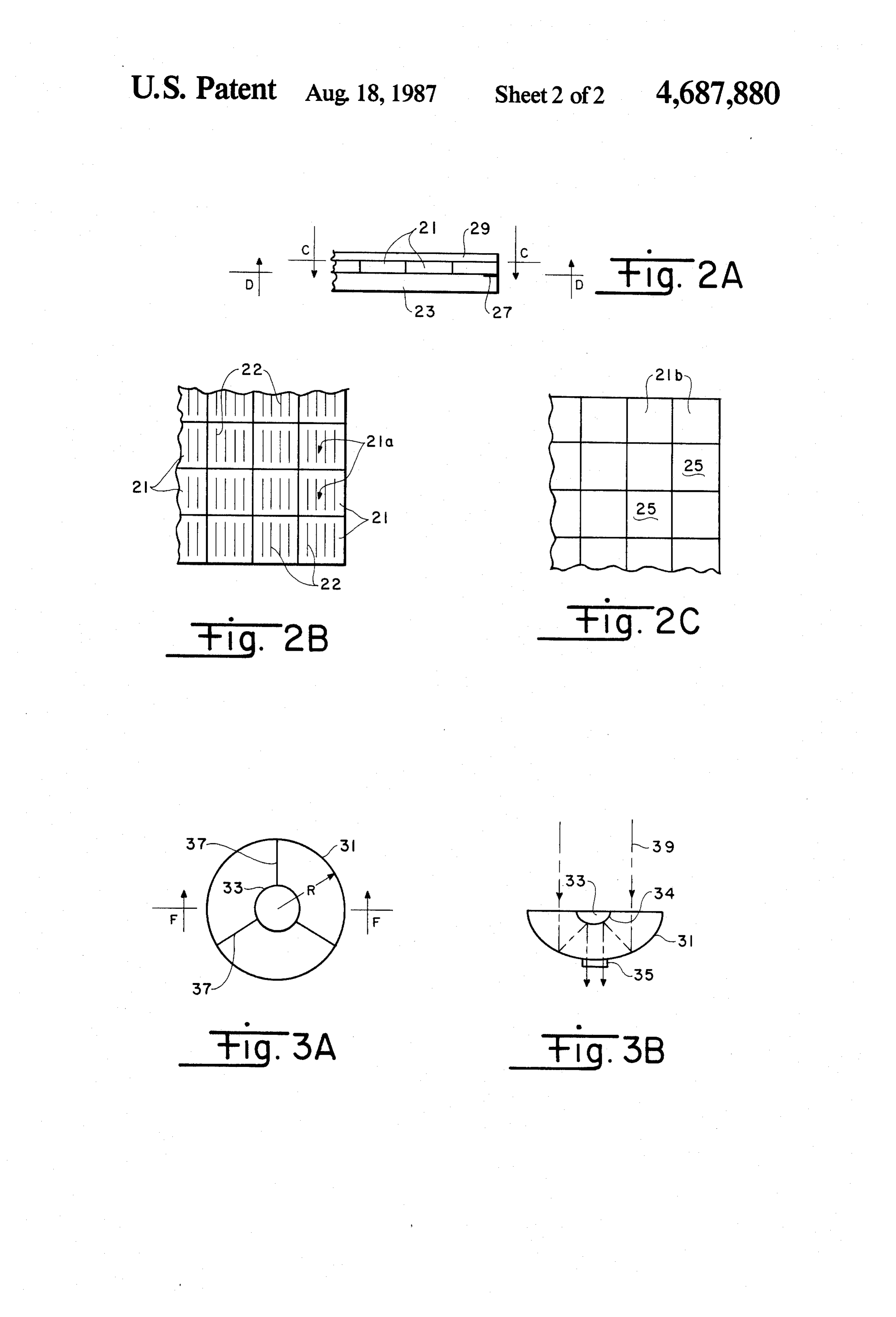
craft or other remote environments. A conventional 50 FIG. 2A is a sectional view along line B-B of FIG. hollow prismatic light tube of square cross section, 1B:
smooth inner surfaces, and grooved outer surface is FIG. 2B is a view along line C-C of FIG. 2A; provided with a plurality of photovoltaic cells mounted FIG. 2C is a view along line D-D of FIG. 2A; FIG. 3A is a view along line E-E of FIG. 1B:
in four rectangular arrays on thin substrates attached to 55 FIG. 3B the grooved surfaces with the cells inwardly facing of is a view along line F-F of FIG. 3A; and the light tube. Light concentrating optics are disposed FIG. 4 shows alternative optics for the system of
Fig, 1a
at the light receiving end of the light tube to illuminate the tube and cells with maximum intensity, and may be DETAILED DESCRIPTION configured to concentrate into the light tube sufficient 60 Referring now to the drawings, FIG. 1A is a sche light for each cell in the arrays equivalent in intensity to matic view in perspective of the tubular luminescence that of the surrounding environment. photovoltaic array system 10 of the invention, which The invention has substantial utility for powering illustrates the modular characteristic of the invention. spacecraft systems requiring high power in remote loca FIG. 1B is an exploded view in perspective of system tions. The system of the invention may be configured in 65 10. FIGS. 1A, 1B illustrate the assembly of three major modular form, is lightweight, and is minimally vulnera cooperating constituent assemblies of system 10. Light ble to damage by particulate impact, and consequently tube 11 is closed at one end and has a plurality of rectan has maximum mission lifetime. gular photovoltaic cell arrays 20 disposed on the sur 5 faces of tube 11 along the lengthwise faces thereof; light invention. The representative optics 30 shown in FIGS. concentrating optics 30 are operatively attached to the 1B, 3A, 3B include a parabolic reflector 31 or equiva light receiving end of light tube 11 substantially as lent concave dish reflector for collecting and focusing shown in FIGS. 1A, 1B. light beam 39 toward a central focusing reflector 33 Reference is now made to FIG. 1B in conjunction having a reflective surface 34 for concentrating light 39 with FIG. 1C, a view along line A-A of FIG. 1A. into a transition element at the light receiving end of Light tube 11 by itself is a substantially conventional light tube 11 in the form of collimating lens 35 which device which converts a beam of light directed there substantially collimates light 39 along axis T within into along central axis T into a radial glow, which re light tube 11. Reflector 33 may be supported at the sults in the transport of light of substantially uniform O focus of reflector 31 by a plurality of thin webs 37 as intensity along length L thereof. Light tube 11 has a required. As light 39 transits light tube 11, prismatic generally square cross section as shown in FIG. 1C and ridges 15 allow light to be radiated outwardly onto comprises four substantially identical walls 13 having arrays 20 while back reflecting the light down light tube smooth internal surfaces 13a defining elongated cham 11 until light 39 transits length L and is back reflected ber 14 of square cross section. A plurality of triangular 15 by reflective surface 18 for further illumination of ar grooves defining prismatic ridges 15 of triangular cross rays 20.
section are formed on the outer surfaces of walls 13 and Referring now to FIG. 4, shown therein is an alterna extend along the lengths thereof. Each prismatic ridge tive arrangement for the light concentrating optics of 15 defines an epex angle 15a equal to 90° and the sur system 10 wherein a suitably sized lens system 40 is faces of each ridge form an angle of 45° angle with inner 20 optically coupled to collimating lens 35' for concentrat surfaces 13a of light tube 11. Light tube 11 may be ing light into light tube 11.
fabricated to substantially any desired length L and System 10 of the invention as just described may be width w, may be obtained commercially, and comprises fabricated to substantially any size, although ordinarily any suitable optically transparent material such as a modular unit of practical size will comprise a light acrylic, glass, or the like. Mirror 17 having an inwardly 25 tube of about 30 to 60 cm in width and about 15 m long, facing reflective surface 18 thereon may be disposed at which will produce about 1 to 2.5 kW at about 200 volts the closed end of light tube 11 opposite optics 30 as (depending on wiring configuration) under usual illumi suggested in FIG. 1B, for back reflection of stray light nation conditions in earth orbit. A plurality of modular within light tube 11.
As illustrated in FIGS. 1B, 1C, a solar cell array 30 units may be assembled to produce a desired output. In assembly 20 of size and rectangular shape correspond the selection of optics 30 (or 40) for inclusion in system 10 of the invention, sufficient light should be collected ing to that of light tube 11 is disposed on each length for adequate illumination of arrays 20 of area 4Lw wise outer surface of light tube 11. Referring addition (FIGS. 1b, 1c). Accordingly, the optics should be sized ally to FIGS. 2A, B, C, shown in FIG. 2A is a sectional to have a radius R to collect light from an area iTR view along line B-B of FIG. 1B. FIG. 2B is a view 35 equal to or greater than 4Lw so that arrays 20 receive along line C-C of FIG. 2A, and FIG. 2C is a view an amount along line D-D of FIG 2A. As shown in FIG. 2A, surroundingofenvironment. light equivalent in intensity to that of the This, however, is not a struc each solar cell array assembly 20 comprises a plurality tural or operational limitation of solar cells 21 of any convenient preselected size (usu of the invention or the scope ofwithin the the contemplation claims, as the inven ally about 2X2, 2X4, or 4X4 cm) and of any conven 40 tional type, i.e., silicon, gallium arsenide, indium phos tion will function at lower light intensities. For opera phide, amorphous silicon, or other, and of cascade or tion of system 10 in orbit, optics 30 may be configured multijunction type as would occur to the skilled artisan to be remotely deployable. Remotely operable aiming guided by these teachings, the same not being limiting means (not shown) may be operatively connected to of the invention herein, Cells 21 are supported on sub 45 system for 10 and used to direct optics 30 toward the sun optimum collection of light 39 intensity.
strate 23 of Kapton TM, Kevlar TM, Kel-FTM, or the like, to provide structural support and protection to In the assembly of optics 30, light tube 11, arrays 20, cells 21 within system 10 (FIG. 1A). The back surfaces and mirror 17 it may be desirable to hermetically seal 21b of cells 21 are attached in suitable fashion to sub system 10 and to enclose an inert gas within light tube strate 23, the active surfaces 21a facing inwardly of 50 11 and in the voids defined between prismatic ridges 15 light tube 11 as suggested in FIG 1B. Back surfaces 21b and covering 29 to protect cells 21 and other compo may conventionally include electrical contacts 25, and nent parts from corrosion. Alternatively, light tube 11 substrate 23 may include current collecting buses 27 for and the voids may be evacuated. To the outer surfaces connection to output 28 (FIG. 1A). Active surfaces 21a of assembled system 10 (FIG. 1A) may be added a suit include the photovoltaic junctions 22 of cells 21. A 55 able covering (not shown) for further protection against transparent protective covering 29 of silicon dioxide, radiation or meteroid impact.
aluminum oxide, or the like may be dispersed in the The photovoltaic system of the invention may be array structure to cushion active surfaces 21a against configured as a single unit or assembled in modular prismatic ridges 15 on light tube 11. Alternatively, cush form of a plurality of such units to provide desirably ioned straps 41 may be spaced along light tube 11 (FIG. high current output. The photovoltaic cells of the sys 1B) to protect the front surfaces of cells 21. tem are enclosed and substantially protected from parti Referring now to FIGS. 3A, 3B in conjunction with cle impact and radiation hazards, which extends cell FIG. 1B, shown in FIG. 3A is an end view of optics 30 and array lifetime and improves overall array perfor along line E-E of FIG. 1B. FIG. 3B is a sectional view mance. the compactness of each modular system allows of FIG. 3A along line F-F. Optics 30 may comprise 65 remote assembly and individual operation, presents a any suitable lens or other light collecting system for small target in a threat environment, minimizes the concentrating light into light tube 11 for illumination of number of optical structures needed for concentration solar cell arrays 20 in generating electricity using the of incident light, and is therefore lighter in weight, 6 simpler in design and more economical in structure and walls of said tube with said front photoactive sur operation than previously known systems. faces of said cells facing inwardly of said tube. The invention, as hereinabove described, therefore 2. The system as recited in claim 1 wherein said cells provides a novel photovoltaic system for converting are mounted on a substrate in said rectangular array. sunlight to electrical power. It is understood that modi- 5 3. The system as recited in claim 1 further comprising fications to the invention as described may be made, as a cushioning layer between said front photoactive sur might occur to one with skill in the field of this inven faces of said cells and said ridges on the outer Surfaces tion, within the scope of the appended claims. There of said tube.
fore, all embodiments contemplated hereunder which 4. The system as recited in claim 1 wherein said opti achieve the objects of the invention have not been 10 cal means includes a collimating lens at said first end of shown in complete detail. Other embodiments may be said tube and a parabolic reflector operatively con developed without departing from the spirit of the in nected to said collimating lens for directing light along vention or from the scope of the appended claims. said axis into said tube.
I claim: 5. The system as recited in claim 1 wherein said opti 1. A photovoltaic solar cell system comprising: 15 cal means includes a collimating lens at said first end of (a) a hollow light tube of substantially optically trans said tube and a focusing lens optically aligned with said parent material, said tube having preselected length collimating lens for directing light along said axis into and first and second ends and including four sub said tube.
stantially identical walls of preselected width hav 6. The system as recited in claim 1 further comprising ing flat inner intersecting surfaces defining along a 20 an end wall closing said second end of said tube. central axis a passageway of generally square cross 7. The system as recited in claim 6 further comprising section extending between said ends, said walls a mirrored surface on the inwardly facing surface of having on the outer surfaces thereof a plurality of said end wall.
triangularly shaped grooves extending along the 8. The system as recited in claim 6 wherein said tube, length of said tube, said grooves defining a plural 25 optical means and end wall are hermetically sealed and ity of ridges having triangular cross section and said passageway is evacuated.
extending along the length of said tube, said triang 9. The system as recited in claim 8 wherein said cells ular cross section of each ridge having an apex are hermetically sealed to said outer surfaces of said angle of 90° and the surfaces of said ridges along tube and the space defined between said ridges and said the length of said tube defining an angle of 45° with 30 front photoactive surfaces of said cells is evacuated. said inner surfaces of said walls; 10. The system as recited in claim 6 wherein said tube, (b) optical means operatively connected to said first optical means and end wall are hermetically sealed and end of said tube for directing light into said tube at said passageway is filled with inert gas. said first end; 11. The system as recited in claim 10 wherein said (c) a plurality of solar cells each having a front photo 35 cells are hermetically sealed to said outer surfaces of active surface and a back surface disposed in a said tube and the space defined between said ridges and rectangular array corresponding in size to the pre said front photoactive surfaces of said cells is filled with selected width of said walls and length of said tube, inert gas. sk : k g : said cells disposed on the outer surfaces of said
Provenance
- Collection
- Patents citing this work
- Pages
- 6
- Method
- pdftotext (the PDF's own text layer) + pdftoppm 300dpi page scans
- Patent office record
- patents.google.com →
- Source
- Google Patents citing-documents table
- Assignee
- The United States Of America As Represented By The Secretary Of The Air Force
- Published
- 1987-08-18
- Transcribed from
- patentimages.storage.googleapis.com →