

patent · US3179824A
Magnetohydrodynamic transformer
20 April 1965
Text
Drawings
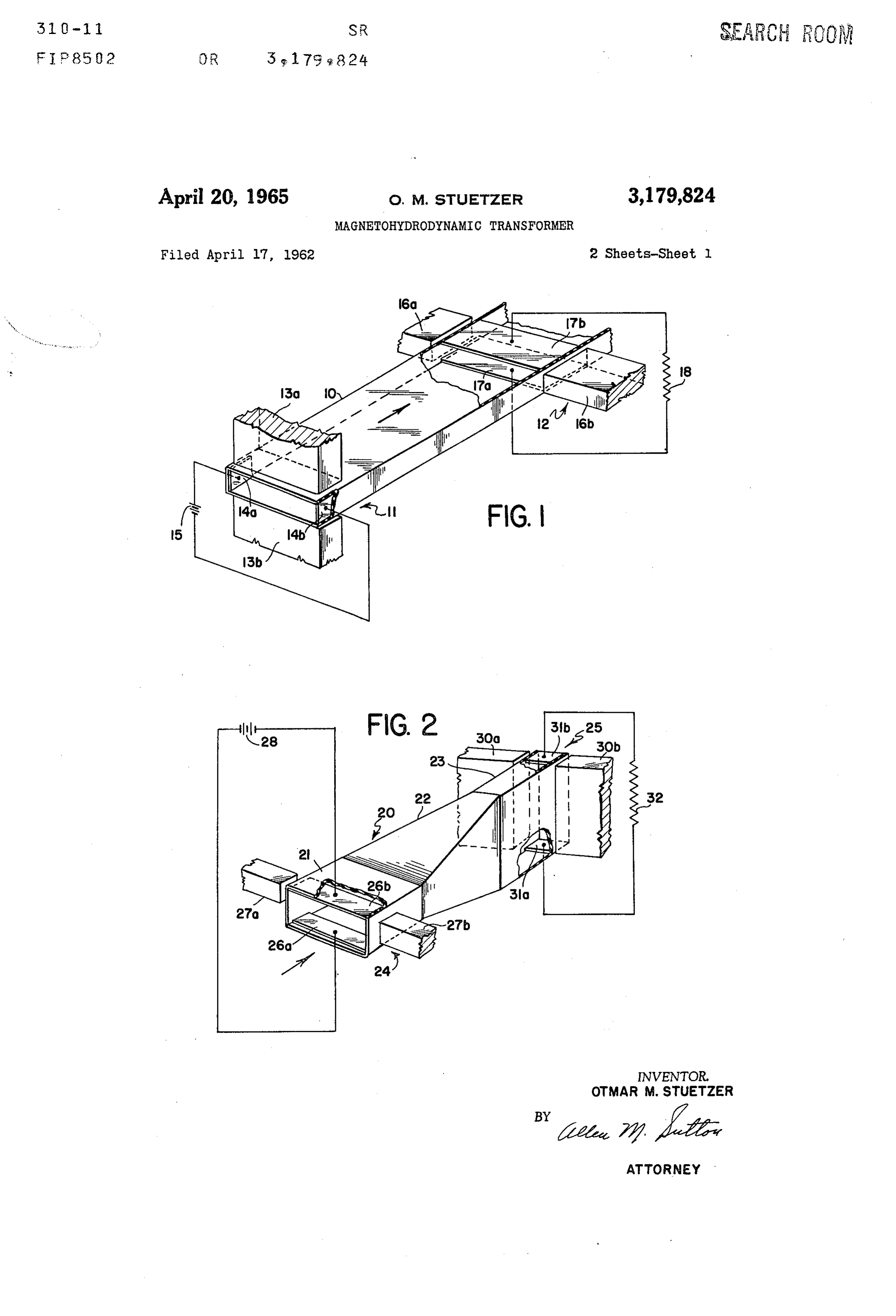
FIG. 4 is a diagrammatic sectional view showing in sulating dividers that are useful in all of the embodiments of the invention.
Page 1drawing sheetscan →
Page 2scan →
April 20, 1965 O. M. STUETZER 3,179,824
Magnetohydrodynamic transformer
Filed April 17, 1962 2. Sheets-Sheet 2 * .247 a 747 a 4 / 4 a 474 a 4- 4 244, 21 a 2 a? a SAYAAssawa 4 4 47 7 4-7 17 ZZ 17, a 7 a 7 a? 47
Inventor,
Otmar m. stuetzer
ATToRNEY
Page 3scan →
Magnetohydrodynamic transformer
Otmar M. Stuetzer, Hopkins, Minn., assignor, by mesne assignments, to Litton Systems, Inc., Beverly Hills, Calif., a corporation of Maryland
This invention relates to electrical transformers, and, more particularly, to a direct current transformer which O operates on the principle of magnetohydrodynamics. Heretofore, there has been no practical device available for transforming direct currents and voltages to other values. Consequently, it has been necessary to employ indirect or roundabout methods to achieve that end. One 5 scheme that has been utilized involves electrically charging a plurality of capacitors connected in parallel, and then discharging the capacitors in series. This requires the use of commutator or switching arrangements and, fur thermore, provides a pulsating direct current that must be 20 smoothed or averaged out. Another method that has been utilized is to convert the direct current to alternat ing current, pass the alternating current through a trans former, and then reconvert the alternating current to direct current. This, of course, is expensive and cumbersome. 25 The present invention provides means for transforming direct currents and voltages which obviate the disadvan tages of the methods that have been necessarily used here tofore. It provides a direct current transformer, which is based on the principles of magnetohydrodynamics, and, 30 because it has extremely low impedance, is particularly adapted for low voltage, high current applications. Magnetohydrodynamics is that field of science which deals with the reactions induced in an electrically con ductive fluid in the presence of a magnetic field. It is, in effect, a union of two branches of physical science, one dealing with fluid flow and the other with electromagnetic fields. For a theoretical treatment of the phenomena of magnetohydrodynamics, reference is made to a book en titled Magnetohydrodynamics by R. K. M. Landshoff, 40 Stanford University Press, 1957, and to a book entitled Magnetohydrodynamics by T. G. Cowling, Interscience Publishers, Inc., New York, N.Y., 1957. In addition, many scientific and technical papers have been published on the subject within the last several years. 45 It is known that if a highly conductive fluid is placed in a magnetic field and current is passed through the fluid at right angles to the magnetic field, the liquid is pumped in a direction normal to both the magnetic field and the direction of current flow. Conversely, if a highly conductive fluid is caused to flow through a magnetic field, current flows through the liquid and a voltage is built up across the liquid in a direction normal to the magnetic field. The present invention utilizes both of these phe 55 nomena to provide a direct current transformer. In its broader aspects, the present invention provides a magnetohydrodynamic transformer comprising means de fining a flow path for a conductive fluid, a magnetohydro dynamic pump in the flow path for pumping the conduc 60 tive fluid, and a magnetohydrodynamic generator in the flow path downstream of the pump for developing an elec tric potential as the conductive fluid flows through the generator. By varying various parameters in the design of the pump and the generator, the transformer of the invention may be adapted for use as either a voltage trans 65 former or a current transformer, i.e. as either a voltage step-up transformer or a current step-up transformer. Be cause the resistance of the conductive fluid is extremely low, the transformer has an extremely low impedance. 70 This is particularly desirable when the transformer is used with other devices which have a matching low impedance,
Patented Apr. 20, 1965 such for example, as in solid state thermoelectric genera tOrS.
The invention will be better understood by reference to the following description of several embodiments, taken in conjunction with the accompanying drawings, in which: FIGS. 1, 2 and 3 are diagrammatic perspective views, with parts broken away, of three embodiments of the invention; and
FIG. 4 is a diagrammatic sectional view showing in sulating dividers that are useful in all of the embodiments of the invention.
FIG. 1 illustrates diagrammatically an embodiment of the invention adapted for use as a current transformer. A duct 10 of uniform rectangular cross-section and made of a non-conductive material provides a flow path for a conductive fluid (not shown), which may flow in the direction shown by the arrow. Although it is not so shown for reasons of simplicity, the duct 10 in practice may form a closed loop so that the conductive fluid can recirculate continuously. In that case, the direction of flow is im material.
A magnetohydrodynamic pump, indicated generally by the numeral 11, is located in the flow path of the con ductive fluid, and a magnetohydrodynamic generator, in dicated generally by the numeral 12, is also located in the flow path downstream from the generator 11.
The magnetohydrodynamic pump 11 comprises a mag net having pole pieces 13a and 13b, located on opposite sides of the duct 10 for providing magnetic flux across the flow path of the conductive fluid. The pump 11 also includes a pair of electrodes 14a and 14b, which are lo cated inside the duct 10, spaced apart on opposite sides of the flow path. The electrodes 14a, 14b, extend along the flow path and are substantially coextensive in that di rection with the magnet pole pieces 13a, 13b. A direct potential source 15 is connected between the electrodes
The conductive fluid that is confined within the duct 10 may be any one of several types, and the invention is in no way limited to the use of any particular fluid. Examples of suitable fluids are the liquid forms of mer cury, gallium, and sodium, or a suitable electrolyte. Fur thermore, the invention also comtemplates the use of a highly conductive hot gas plasma as the conductive fluid. The principal qualification is that the fluid must be highly conductive, so that current may readily flow through the fluid between the electrodes 14a and 14b.
The magnetohydrodynamic generator 12, located down stream of the pump 11, is very similar in construction to the pump 11. It includes a magnet having pole pieces 16a and 16b located on each side of the duct 10 for pro viding magnetic flux across the flow path of the conduc tive fluid. Electrodes 17a and 17b are located inside the duct 10 and are spaced apart on opposite sides of the flow path. The electrodes 7a and 17b extend along the flow path and, in the case of a current transformer, are spaced closer together than are the electrodes 14a and 14b in the pump 11. In the present instance, that is ac complished by placing the pump electrodes on the sides and the generator electrodes on the top and bottom of the duct. An electrical load, shown as a simple resistor 18, is connected between the electrodes 17a and 17b of the generator 12.
When current from the source 15 flows through the conductive fluid between the electrodes 14a, 14b, normal to the direction of the magnetic field, a physical force is exerted on the fluid which causes it to move or be pumped along the duct 10. The conductive fluid pumped by the pump 1 then flows through the magnetic field between the pole pieces 16a, 16b, in the generator 12, and a voltage is built up normal to the field between the 4 electrodes 7a and 17b. Thus, current flows through the than that between the pump electrodes or the magnetic conductive fluid between electrodes 17a, 17b, and through flux in the generator must be greater than that in the the electrical load 18 connected between the electrodes. pump, or both.
The area of the generator electrodes may be selected to The reasons that the electrodes 31a, 3b, in the mag provide an internal impedance that is of the same order 5 netohydrodynamic generator 25 are smaller in area than of magnitude as the impedance of the load 18. are the electrodes in the magnetohydrodynamic pump 24 If Small flow losses are assumed, it has been found is to provide an internal impedance between the electrodes that the following relationship is valid for transformation 31a, 3b, that is of the same order of magnitude as the ratios smaller than 5:1. The relationship is electrical load 32 connected between the electrodes. IO FIG. 3 illustrates another embodiment of the invention
U-I-B2X adapted for use as a voltage transformer. The trans UTITBX, former shown in FIG. 3 is very similar to that shown in where U and U2 are the voltages between the electrodes FIG. 2, and comprises a duct 34 for providing a flow path of the pump and generator, respectively; I and I2 are the for a conductive fluid, a magnetohydrodynamic pump 24, currents flowing between the electrodes in the pump and 5 and a magnetohydrodynamic generator 25. The pump generator, respectively; B, and B2 are the strengths of the 24 and the generator 25 may be identical with those previ magnetic fluxes existing across the flow path in the pump ously described bearing the same reference numerals. and generator, respectively; and XI and X are the dis The duct 30 differs from that shown in FIG. 2 in that it is tances between the electrodes in the pump and generator, of uniform cross section and is merely twisted by sub respectively. Thus, it is seen that by making the spacing 20 stantially 90° between the locations of the pump and gen between the electrodes 17a, 17b, of the generator 12 less erator. Thus, it provides the same pump and generator than that between the electrodes 14a, 14b in the pump sections shown in FIG. 2 but without the use of an adapter 11, a current transformer is provided, wherein the in section to interchange the cross-sectional dimensions. Its crease in current is substantially inversely proportional operation is the same as that of the transformer described to the spacing between the electrodes in the pump and 25 with reference to FIG. 2.
generator assuming that B1 and B2 are equal. Similarly, In both of the voltage transformer embodiments shown if the generator electrodes are spaced farther apart than in FIGS. 2 and 3, the flow paths provided by the ducts 20 the pump electrodes, a voltage step-up will be obtained. and 34 may be closed so that the direction of flow of the It is pointed out that the current transformer shown conductive fluid is unimportant. The voltage sources 15 in FIG. 1 may be converted to a voltage transformer by 30 and 28 may be connected between the pump electrodes interchanging the voltage source 15 and the load 18. with either polarity.
Thus the pump and transformer are interchanged. Either of the voltage transformers of FIGS. 2 and 3 FIG. 2 illustrates an embodiment of the invention may be converted to a current transformer by interchang adapted for use as a voltage transformer. It differs from ing the potential source and the electrical load. Thus, the embodiment shown in FIG. 1 not only in that the elec 35 the pump becomes a generator, and the generator becomes trodes in the magnetohydrodynamic generator section a pump.
are spaced farther apart than those in the pump section, It has been found in practice that using a duct with but also in that the straight duct 10 of uniform cross sec 20 mm. X 0.5 mm. cross-section, B1=B2= 10,000 gauss, tion has been replaced by a duct 20 having a varying U=.001 v. and I=10 amps., one can obtain up to .006 v. cross Section. The duct 20, which may provide a closed 40 across a load of 0.01 ohm.
flow path for a conductive fluid, includes a pump section It has been found that, in the generator stage of the 21, an adapter Section 22, and a generator section 23. The transformer of the invention, the conductive liquid itself adapter section 22 serves merely to connect the pump and provides a return path for the electric current that is gen generator sections 21 and 23 and to reverse the cross-sec erated. Thus, the liquid is effectively connected in par tional dimensions of the duct between the pump and allel with the electrical load and tends to short circuit the generator Sections. load. This effect can be minimized by subdividing the The pump section 21 of the duct contains a magneto flow path on each side of the generator stage. Such an hydrodynamic pump, indicated generally by the numeral arrangement is shown in FIG, 4.
24 and the generator section 23 of the duct contains a The arrangement shown in FIG. 4 may be advanta magnetohydrodynamic generator, indicated generally by 50 geously applied to any one of the embodiments of the the numeral 25. invention previously described. It comprises a plurality The pump 24 differs from the pump 11 (FIG. 1) in of insulating dividers 35 conventionally mounted within a that electrodes 26a and 26b are spaced apart across the duct 36, which divide the duct into a plurality of hori shorter dimension of the rectangular duct rather than Zontal sections. The dividers 35 are substantially par across the longer dimension. Also the magnet pole 55 allel and extend in the direction of flow of the conductive pieces 27a and 27b that provide flux across the duct at fluid, both upstream and downstream from a generator right angles to the direction of flow are smaller than 37. In fact, they may extend substantially from the those previously described. Of course, a direct potential downstream edge of a pump 38 clear to the upstream edge Source 28 is connected between the electrodes 26a, 26b. 60 of the generator 37 and then downstream from the gen The generator 25 differs from the generator 12 shown erator for Some distance. Thus, the flow of current in FIG. 1 in several ways. First, because the configura through the conductive fluid on each side of the generator tion of the duct has changed, magnet pole pieces 30a and is substantially reduced because there is no direct path 30b, which provide magnetic flux across the flow path, through the fluid on either side of the generator. are considerably larger than those shown in FIG. 1. Also Although several embodiments of the transformer of electrodes 31a and 31b, which are located on the top and the invention have been described, it is apparent that bottom sides of the duct, are farther apart because of many modifications and changes may be made by one the configuration of the duct. An electrical load, shown skilled in the art without departing from the true scope as a simple resistor 32, is connected between the elec and spirit of the invention.
trodes 3a and 31b. What is claimed is:
In operation, the embodiment of the invention shown 70 1. A magnetohydrodynamic transformer comprising a in FIG. 2 is very similar to that previously described with nonconductor rectangular duct forming a flow path for a reference to FIG. 1. They both operate in accordance conductive fluid of low resistance; a magnetohydrody with the formula previously set forth. It is pointed out, namic pump including magnetic poles located on opposite however, that for a voltage transformer (FIG. 2) the sides of Said duct for providing magnetic flux across Spacing between the generator electrodes must be greater 75 Said flow path, a first pair of electrodes inside said duct 5 on opposite sides thereof and extending along said flow pump and said generator, respectively, B1 and B2 are the path substantially coextensive with said magnetic poles, strengths of the magnetic flux existing across the flow and a direct potential source connected to said first pair path in said respective pump and generator, and X1 and of electrodes; a magnetohydrodynamic generator in said X are the distances between the first and second pairs flow path downstream of said pump including magnetic of electrodes of said pump and said generator, respectively; pole pieces located on opposite sides of said duct for said distance between said second pair of electrodes in providing magnetic flux across said flow path, a second said flow path of said generator being greater than said pair of electrodes located inside said duct and extending distance between said first pair of electrodes in said flow on opposite sides of said flow path substantially coexten path of said pump.
sive with said magnetic pole pieces; and an electrical load O 3. A magnetohydrodynamic transformer comprising a connected to said second pair of electrodes; said magneto nonconductor rectangular duct forming a flow path for hydrodynamic pump and said magnetohydrodynamic gen a conductive fluid of low resistance; a magnetohydro erator having a transformer relationship of dynamic pump including magnetic poles located on oppo site sides of said duct for providing magnetic flux across 5 said flow path, a first pair of electrodes inside said duct
UTITB X on opposite sides thereof, and extending along said flow where U and U2 are the voltages between the first and path substantially coextensive with said magnetic poles, second pairs of electrodes of said pump and said genera and a direct potential source connected to said first elec tor, respectively, I and I are the currents flowing be trodes; a magnetohydrodynamic generator in said flow tween the first and second pairs of electrodes of said pump 20 path downstream of said pump including magnetic pole and said generator, respectively, B and B are the pieces located on opposite sides of said duct for providing strengths of the magnetic flux existing across the flow magnetic flux across said flow path, a second pair of path in said respective pump and generator, and X and electrodes located inside said duct and extending on oppo Xa are the distances between the first and second pairs of site sides of said flow path substantially coextensive with electrodes of said pump and said generator, respectively; 25 said magnetic pole pieces; and an electrical load con said distance between said second pair of electrodes in nected to said second pair of electrodes; said magneto said flow path of said generator being less than said dis hydrodynamic pump and said magnetohydrodynamic gen tance between said first pair of electrodes in said flow erator having a transformer relationship of path of said pump.
2. A magnetohydrodynamic transformer comprising a 30 U21-B2X2 nonconductor rectangular duct forming a flow path for UTI BX a conductive fluid of low resistance; a magnetohydro where U and U are the voltages between the first and dynamic pump including magnetic poles located on oppo second pairs of electrodes of said pump and said generator, site sides of said duct for providing magnetic flux across respectively, I and I2 are the currents flowing between the said flow path, a first pair of electrodes inside said duct 35 first and second pairs of electrodes of said pump and on opposite sides thereof and extending along said flow said generator, respectively, B1 and B2 are the strengths path substantially coextensive with said magnetic poles, of the magnetic flux existing across the flow path in said and a direct potential source connected to said first pair respective pump and generator, and X and X2 are the of electrodes; a magnetohydrodynamic generator in said distances between the first and second pairs of electrodes flow path downstream of said pump including magnetic 40 of said pump and said generator, respectively; the area pole pieces located on opposite sides of said duct for of said second electrodes being smaller than the area providing magnetic flux across said flow path, a second of said first electrodes; the internal impedance of said pair of electrodes located inside said duct and extending generator being substantially the same magnitude as the on opposite sides of said flow path substantially coex impedance of said electrical load. tensive with said magnetic pole pieces; and an electrical 45 References Cited by the Examiner load connected to said second pair of electrodes; said magnetohydrodynamic pump and said magnetohydrody UNITED STATES PATENTS namic generator having a transformer relationship of 1,196,511 8/16 Borger ---------------- 310-11
UTITBX FOREIGN PATENTS where U and U are the voltages between the first and 1,121,202 1/62 Germany.
second pairs of electrodes of said pump and said gen erator, respectively, I and Ia are the currents flowing MILTON O. HIRSHFIELD, Primary Examiner. between the first and second pairs of electrodes of said 55 DAVID X. SLINEY Examiner.
Provenance
- Collection
- Patents citing this work
- Pages
- 5
- Method
- pdftotext (the PDF's own text layer) + pdftoppm 300dpi page scans
- Patent office record
- patents.google.com →
- Source
- Google Patents citing-documents table
- Assignee
- Litton Systems Inc
- Published
- 1965-04-20
- Transcribed from
- patentimages.storage.googleapis.com →