

patent · US3385983A
Magnetohydrodynamic energy converter
28 May 1968
Text
Page 1bibliographic recordscan →
3 O- 1 SR Siri is a Kisii
May 28, 1968 . 3OHN ET A. 3,385,983
MAGNETOHYDRODYNAMIC ENERGY CONVERTER
Filed April 15, l965 2 Sheets-Sheet l
Thorns Bohn
Hans-Arno Classen
Karl A. Sfragdal
INVENTOR.
Attorney
Drawings
Page 2drawing sheetscan →
Page 3scan →
United States Patent Office 3,385,983 Patented May 28, 1968
3,385,983 Wall whereas electrons will impinge upon the outer wall, MAGNETOHYDRODYNAMIC ENERGY the intensity of the magnetic field may be so calculated CONVERTER in relation to the speed of the gas stream that the particles Thomas Bohn, Juich, Hans-Arno Claassen, Aachen, and must attain a certain degree of ionization before being Karl Alfred Stradal, Julich, Germany, assignors to deflected into contact with the inner electrode. The latter Kernforschungsanlage Juich des Landes Nordrhein could be formed as a layer on a helically grooved cylin Westfalen-e.V., a corporation of Germany der of dielectric material which also forms the transverse Filed Apr. 15, 1965, Ser. No. 448,305 channel walls; the outer electrode may then be con Claims priority, application Germany, Apr. 16, 1964, Stituted by a helical Zone on a continuous metallic sleeve. K 52,699 O Surrounding the dielectric body. It is, however, also pos 7 Claims. (C. 310-11) sible to shape each electrode as a narrow metallic strip or as a Sticcession of such strips in conductive contact
ABSTRACT OF THE DISCLOSURE with one another, and to separate adjacent turns of the helically wound strips by a similarly wound insulating
Magnetohydrodynamic energy converter wherein an 5 member constituting the transverse channel walls. ionized gas is passed through a helical channel within The electrodes should, of course, consist of a metal or a magnetic field oriented in the direction of the channel alloy, e.g., tantalum, capable of withstanding the high axis, the channel being bounded by inner and outer con temperatures contemplated; similarly, a dielectric (e.g., ductive walls across which a load is connected to abstract ceramic) material of suitable refractoriness will have to electrical energy from charged particles of the gas stream. 20 be used for the nonconductive channel members.
The invention will be described in greater detail with reference to the accompanying drawing in which:
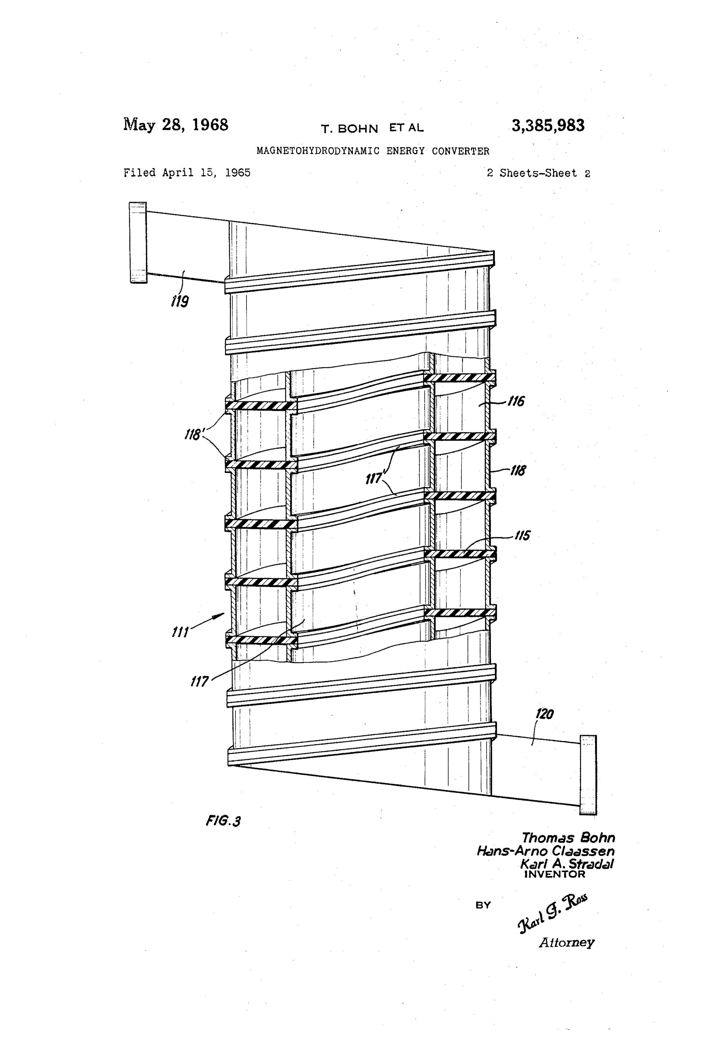
Our present invention relates to a magnetohydro FIG. 1 is a sectional view of a magnetohydrodynamic dynamic energy converter of the type wherein a hot ion converter embodying our invention; ized gas, such as a metal vapor, is conducted through a FIG. 2 is an axial view, partly in section, of the con magnetic field which separates its oppositely charged par verter shown in FIG. 1 diagrammatically illustrating its ticles So as to let them impinge upon a positive and a mode of operation; and negative electrode, respectively, on opposite sides of the FIG. 3 is a view similar to FIG. 1, showing part of a gas channel. modified converter according to the invention, In FIGS. 1 and 2 we have shown a magnetohydro
Such hot gases, e.g., mercury or cesium, undergo pro 30 dynamic gressive ionization so that electrons and positive ions con energy converter 10 having a channel structure tinue to separate as the gas moves through the magnetic 11 surrounded by an electromagnetic coil 12. Channel field generally at right angles thereto. In order to maintain structure 11 comprises a generally tubular body 14 of a reasonable efficiency, conventional systems of this type insulating material which is formed integral with a helical require rather lengthy channel structures and a corre outer rib 5 of rectangular profile defining opposite walls spondingly distributed source of magnetic flux. In a typical of a gas channel 16 of rectangular cross-section. The two prior-art energy converter of this type, the maximum remaining walls of channel 16 are formed by a conduc magnetic induction was around 2 Webers per m2 of flux tive strip 17, wound helically along the outer surface of core 14 between adjacent turns of rib 15, and by a con area. On the other hand, these converters were of a rather 40 fronting bulky construction with an average weight of about 1 ton helical zone of a metal cylinder 18 which closes per liter of channel volume. the open spaces between these turns. Channel 16 com The general object of our present invention is to pro municates at opposite ends with an inlet tube 19 and an vide a compact and highly efficient energy converter of of the tube outlet 20 whose internal cross-section matches that channel and which open tangentially into the an the character referred to.
In accordance with this invention, we provide means nular clearance between core 14 and cylinder 18. for guiding the hot ionized gas, such as a metal vapor Coil 12 is connected across an energizing circuit in heated to a temperature on the order of 3000 C., in a cluding a pair of conductors 2, 22 which lead to the direction generally transverse to a magnetic field through positive and the negative terminal, respectively, of a direct a curved channel forming a plurality of turns, specifically 50 current source not further illustrated. In the preferred mode of realization, in which the coil 12 is maintained a helicoidal or helical channel whose axis is substantially in a state of superconductivity, conductors 21 and 22 may parallel to the direction of the magnetic flux. Advan be energized from a battery or other source of relatively tageously, this channel has a generally rectangular cross low voltage. This superconductive state may be brought section defined by a pair of helical electrodes forming the about, in a manner known per se, by cooling means illus lateral channel walls and successive turns of a helically 55 trated diagrammatically as a conduit 23 wound around convoluted dielectric strip defining the two remaining (i.e., the coil 12 and adapted to carry a suitable cooling fluid, transverse) walls of the channel, the two helical elec e.g. liquid helium, which is circulated therethrough by trodes being located along two imaginary coaxial cylin means not shown.
der surfaces. Where the source of magnetic flux consists of one or more electromagnetic coils with a single axis, 60 18The inner metallic strip 17 and the outer metal cylinder constitute respective electrodes shown connected across the latter advantageously coincides with the axis of the a load 24 by means of output leads 25 and 26. The cur helical channel and of the two imaginary cylindrical sur rent flow in output circuit 24–26 is generated by an faces whereon the inner and outer channel walls are located. ionized gas admitted at high temperature into the chan In a preferred embodiment, the electromagnetic coil 65 nel 6 by way of inlet 19 and discharged therefrom via or coils are wound of wire or other conductor elements outlet 20, the path of the gas along channel 6 being maintained in a superconductive state by suitable cooling Substantially perpendicular to the lines of flux of a con means known perse so that a magnetic field of the desired stant magnetic field creating a flux B in axial direction intensity can be generated with the aid of a very low of coil 12 and channel 16. As indicated in FIG. 2, the energizing voltage. 70 polarity of the flux B is so chosen that positive ions in If the magnetic field is constant and so oriented that channel 16 are deflected inwardly toward inner electrode the positively charged ions will strike the inner channel 17 whereas negative electrons strike the outer electrode
Page 4scan →
18. The intensity of this flux, suitably controlled by the nel; inlet means for admitting a hot ionized metal vapor flow of a current of chosen magnitude through coil 12, with a temperature on the order of 3000 C. to an en and the velocity of the gas stream are advantageously trance end of Said channel; and a load circuit connected such that gas particles in a lower state of ionization will acroSS Said inner and outer conductor means. experience a magnetic deflection substantially correspond 5 3. A converter as defined in claim 2 wherein said en ing to the curvature of channel 16 whereas more highly ergizing means includes cooling means for maintaining charged positive ions will be deflected inwardly to strike said coil means in a superconductive state. the electrode strip i7. Uncharged particles, of course, 4. A converter as defined in claim 2 wherein said inner are physically constrained to move within the confines of and outer conductor means extend along two imaginary channel 16. The average axial velocity of the particles, on O coaxial cylinder surfaces.
the other hand, is constant and independent of ionization S. A magnetohydrodynamic energy converter compris over the full channel length. In this manner, thermal dis ing a Source of magnetic flux; guide means forming a sub sociation and magnetic separation of charges will take stantially helical channel of substantially rectangular place over the entire channel length so that the system cross-section with an axis substantially parallel to the will operate with very high efficiency. direction of said flux, said guide means including a heli In FIG. 3 we have shown a modified channel Struc cally wound first conductor and a helically wound second ture 11 composed of a helically wound inner metal strip conductor defining lateral walls of said channel, said guide 17, a helically wound outer metal strip 18 coaxially means further including dielectric strip means defining registering therewith, and a helically wound insulating transverse walls of said channel; inlet means for admitting Strip iS whose rectangular profile is perpendicular to a hot ionized gas to an entrance end of said channel; that of strips 7 and 118 which are provided with re and a load circuit connected across said first and second spective end flanges 117 and 18 receiving the strip conductors.
115 between them. The result of this construction is again 6. A magnetohydrodynamic energy converter compris a helical channel i6 of rectangular cross-section having ing uniaxial electromagnetic coil means provided with conductive inner and outer walls 17 and 118 to serve electric energizing means for producing a magnetic flux: as output electrodes and further having transverse non guide means forming a substantially helical channel of conductive walls 15 insulating these electrodes from each Substantially rectangular cross-section centered on the axis other. As in the embodiment of FIGS. 1 and 2, an ionized of Said flux, said guide means including a helically wound gas heated to high temperatures is admitted at an inlet first conductor and a helically wound second conductor 19 and discharged at an outlet 120. Furthermore, again 30 defining lateral walls of said channel, said guide means as in the preceding embodiment, a magnetic field coaxial further including dielectric strip means defining transverse With the helical channel structure is produced by means walls of said channel; inlet means for admitting a hot not shown in FIG. 3, preferably one or more coils uni ionized gas to an entrance end of said channel; and a axially disposed around the structure and rendered super load circuit connected across said first and second con conductive by suitable cooling means. ductors.
The operation of the system of FIG. 3 is substantially 7. A magnetohydrodynamic energy converter compris identical with that of FIGS. 1 and 2. If desired, the strips ing uniaxial electromagnetic coil means provided with i5, 156 and 18 can be longitudinally subdivided into electric energizing means for producing a constant mag juxtaposed sections (conductively interconnected in the netic flux; guide means forming a substantially helical case of each electrode 117 and 18) whereby the structure channel of Substantially rectangular cross-section cen can be extended at will by the inclusion of additional sec tered on the axis of Said flux and curving in the direction tions. of deflection of positive ions by said flux, said guide means We claim: including a helically wound inner conductor and a heli i. A magnetohydrodynamic energy converter compris cally wound outer conductor defining lateral walls of ing a Source of constant magnetic flux; guide means form Said channel, said guide means further including dielec ing a substantially helical channel with an axis substan tric Strip means defining transverse walls of said chan tially parallel to the direction of said flux and curving in nel; inlet means for admitting a hot ionized metal vapor the direction of deflection of positive ions by said flux, with a temperature on the order of 3000 C. to an en Said guide means including inner conductor means and trance end of Said channel; and a load circuit connected Outer conductor means defining lateral walls of said chan acroSS Said inner and outer conductors. nel; inlet means for admitting a hot ionized metal vapor to an entrance and of Said channel; and a load circuit con References Cited nected across said inner and outer conductor means.
2. A magnetohydrodynamic energy converter compris UNITED STATES PATENTS ing uniaxial electromagnetic coil means provided with 55 2,715,686 8/1955 Asti ---------------- 3 10-11 electric energizing means for producing a constant mag 3,034,002 5/1962 Carlson ------------- 310-11 netic flux; guide means forming a substantially helical 3,179,824 4/1965 Stuetzer ----------- 310-11 channel centered on the axis of said flux and curving in 3,110,843 11/1963 Donaldson --------- 315-11 the direction of deflection of positive ions by said flux, 3,239,697 3/1966 Stekly --------------- 310-11 Said guide means including inner conductor means and 60
Outer conductor means defining lateral walls of said chan DAVID X. SLINEY, Prinary Examiner.
Provenance
- Collection
- Patents citing this work
- Pages
- 4
- Method
- pdftotext (the PDF's own text layer) + pdftoppm 300dpi page scans
- Patent office record
- patents.google.com →
- Source
- Google Patents citing-documents table
- Assignee
- Kernforschungsanlage Juelich
- Published
- 1968-05-28
- Transcribed from
- patentimages.storage.googleapis.com →