

patent · US3195606A
Combustion and heating apparatus
20 July 1965
Text
Drawings
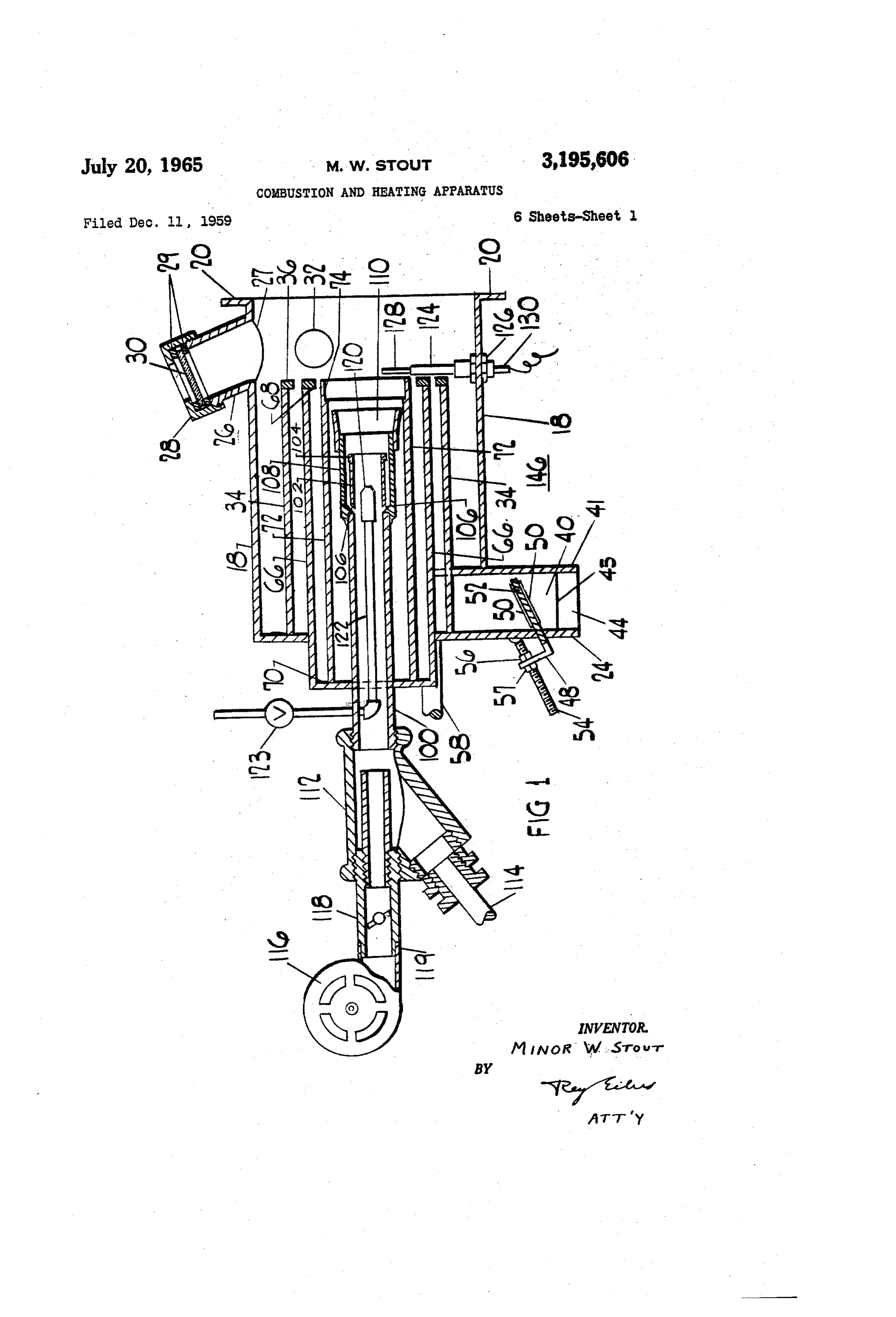
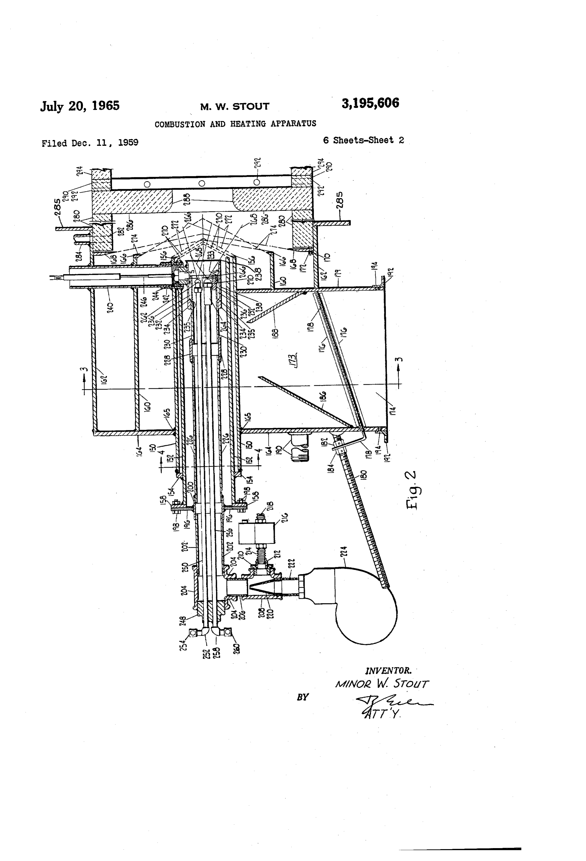
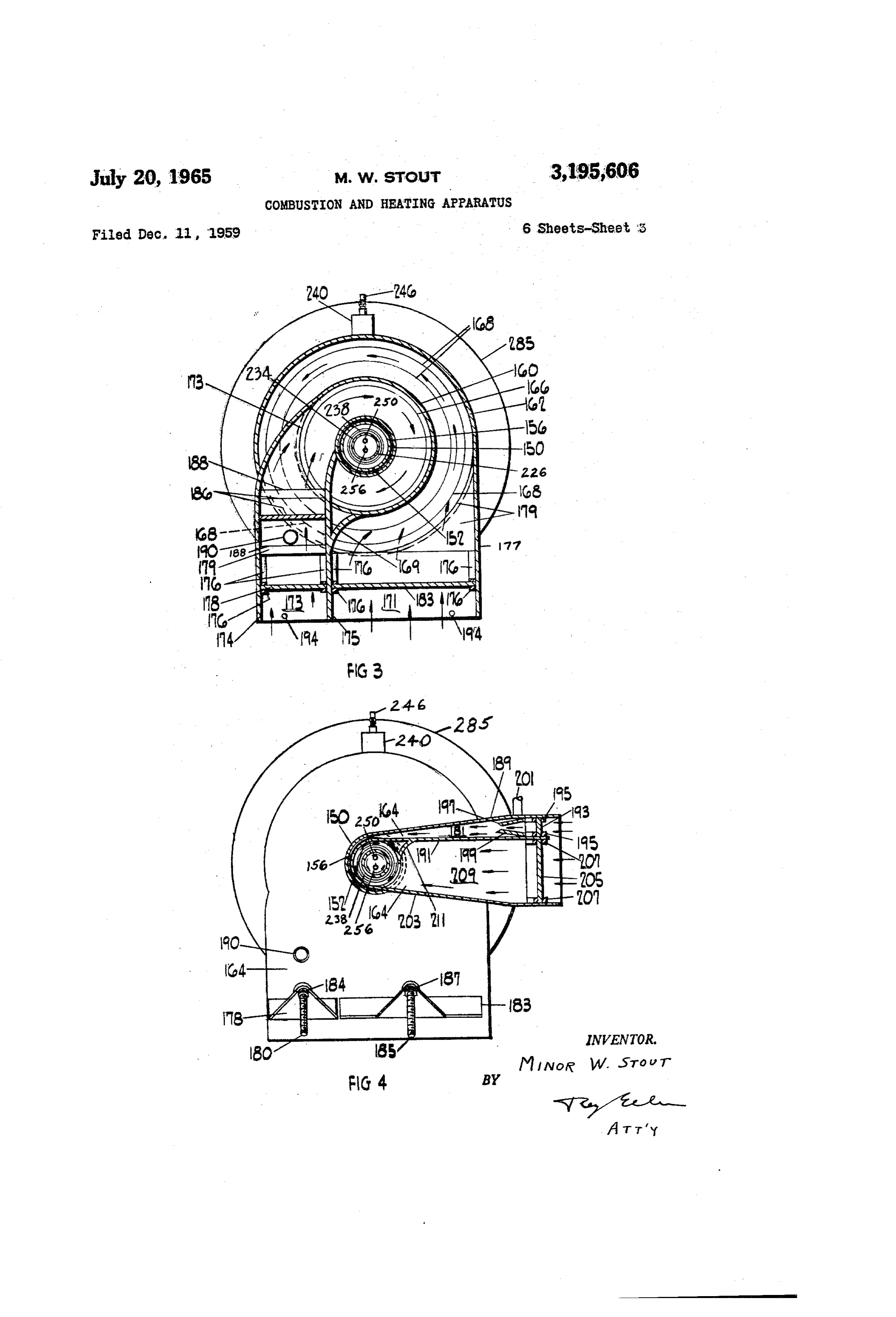
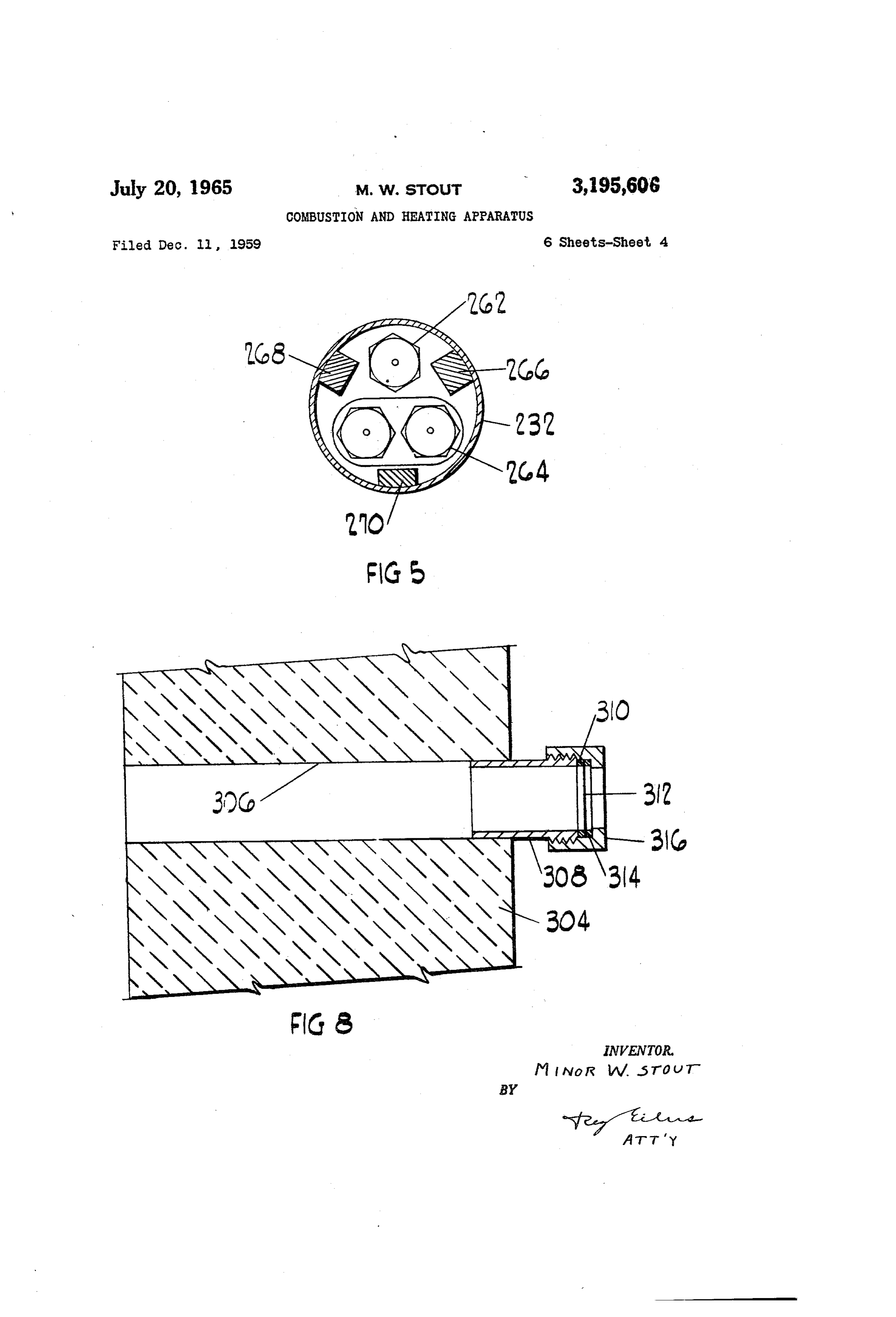
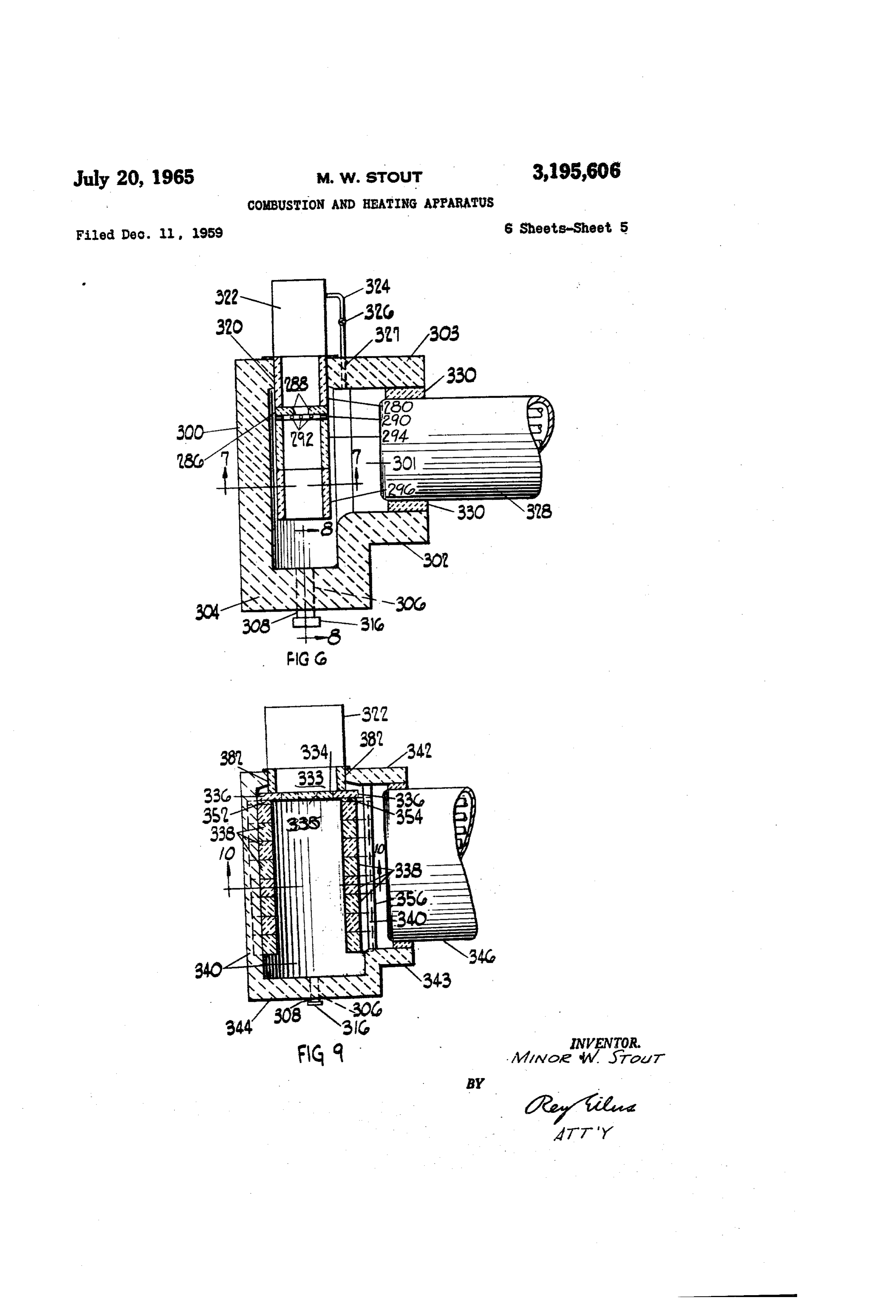
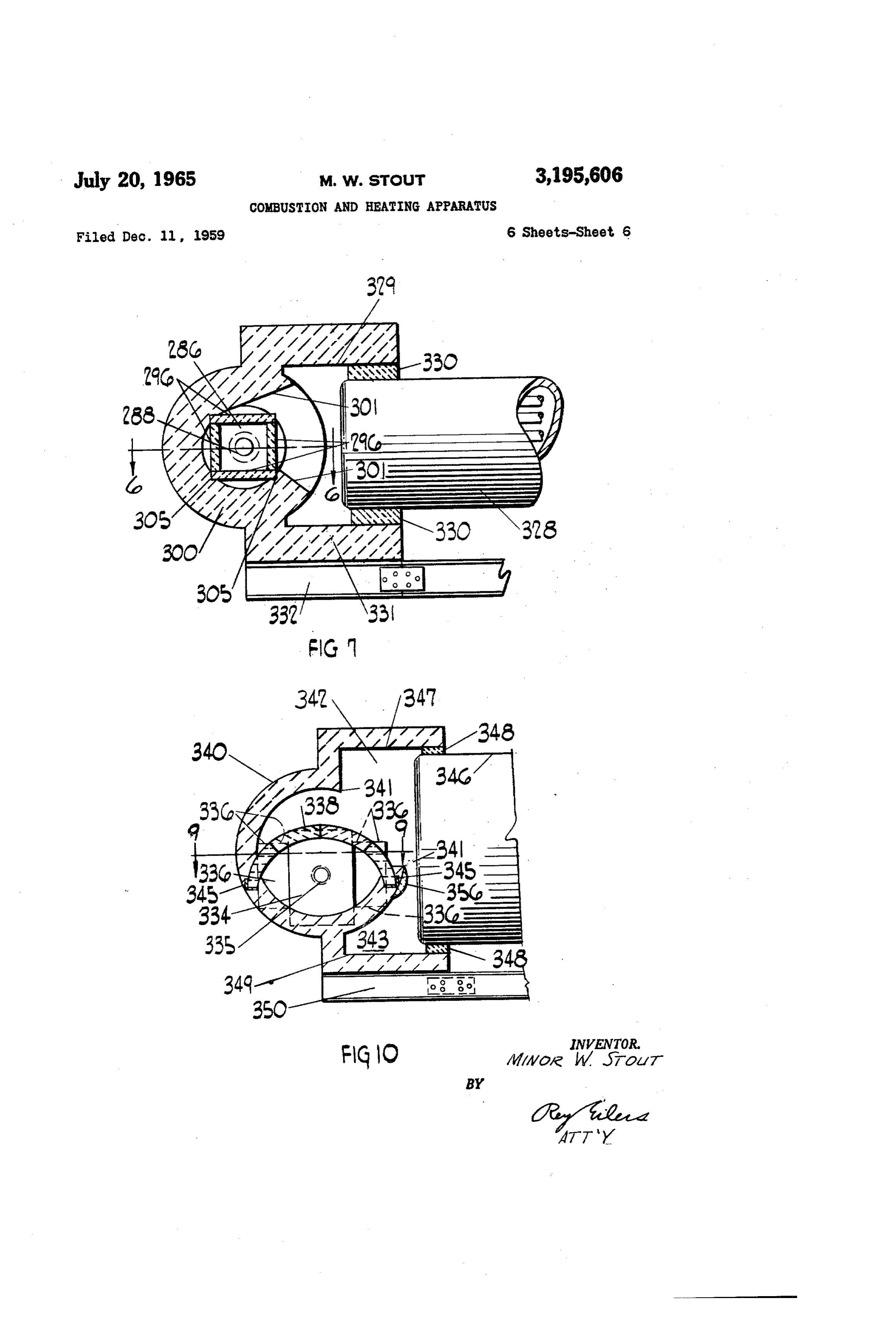
FIG. 2 is a vertically-directed, longitudinal section which fluid and precisely predetermine an annular nozzle from through another form of combustion head that embodies can issue. The inwardly directed flange 36 will the principles and teachings of the present invention, coact with the exterior of a cylinder 66 to define a second 50 precisely predetermined nozzle for fluid. The cylinder 66
FIG. 3 is a sectional view through the combustion head will have its left-hand end extending through a circular of FIG. 2, and it is taken along the plane indicated by the opening in the end wall 24, and the exterior of the cylinder
FIG. 4 is anothersectional view through the combustion define that circular welded to the portions of the wall 24 which opening. . .
Page 1drawing sheetscan →
Page 2drawing sheetscan →
Page 3drawing sheetscan →
Page 4drawing sheetscan →
Page 5drawing sheetscan →
Page 6drawing sheetscan →
Page 7scan →
United States Patent Office SSLLSSSLSSLSSLSLSSLSLSSLSLSSLSSSSSCSCSSSSLSSSSLSSSSSSLSCSLBLBLLLLSSSLSLCLSMSSSLSLSLSLSLSCCLLLSSLSSSMSSSLSSLLSLSLSSLSLSSMSSSLSCLLLSCS Patented July 20, 1965 blown off although air and fuel are moving past the pilot 3,195,606 nozzle at a rapid rate. COMUSTON ANS SEANS APPARATUS The combustion apparatus provided by the present Minor W. Stout, Webster Groves, Mio. invention includes a combustion throat which is ex (782 Vianchester, S. Louis, Mo.) ternal of the fire tubes or water tubes of the boiler or Filed Dec. 1, 1959, Ser. No. 85S,963 is external of the oil-heating tubes of an oil-cracking } Clainns. (C. 1158-) Still. That combustion throat has a refractory wall in This invention is a continuation-in-part of the invention register with the outlet of the combustion head, and disclosed in my co-pending application Ser. No. 352,498 the flame from the combustion apparatus will strike that which was filed May 1, 1953 for Combustion Apparatus, 10 fuel Wall and then rebound back toward further oncoming now Patent No. 3,032,096. and the products of combustion. As a result, there This invention relates to improvements in combustion is a re-entrant movement of the burning fuel and prod apparatus. More particularly, this invention relates to im lucts of combustion which provides greatly increased provements in combustion apparatus providing improved turbulence of the and greatly increased heating and ignition oncoming fuel and the products of combustion.
combustion of the fuel. 5
It is therefore an object of the present invention to pro As a result, full and complete combustion of large quanti vide improved combustion apparatus providing improved ties very of fuel can be attained in a very short time and in a short distance. It is therefore an object of the pres combustion of the fuel.
The combustion apparatus provided by the present in ent invention to provide combustion apparatus which has vention fosters prompt and complete burning of the fuel 20 ais combustion in register throat wherein a wall of refractory material with the outlet of the combustion head and by providing a continuous pilot and by forcing the fuel which will cause burning fuel and products of combustion that is to be burned to pass through the flame of that to rebound toward the combustion head. pilot. As that fuel passes through the pilot fame it is heated and ignited and is caused to burn rapidly. It is willTheberefractory heated to wall in register with the combustion head incandescence by the burning fuel and therefore an object of the present invention to provide a products of combustion which engage it. The incandes combustion apparatus wherein a continuous pilot flame is cence of that refractory wall is desirable because it will maintained and wherein the fuel that is to be burned is enhance the heating, ignition and burning of any fuel that forced to pass through that pilot flame. strikes that wall.
The fuel is forced to pass through the pilot flame by The combustion head and the refractory wall in register disposing the pilot fiame so it is coextensive with part of 30 with it define a line that is transverse of the direction the flame from the fuel nozzle, and by disposing the pilot which the products of combustion must follow as they flame so the fuel from the fuel nozzle must strike and transfer their heat to the heat-absorbing surfaces of the penetrate the pilot fame. As a result, the fuel from the boiler or other device to be heated. Furthermore, the fuel nozzle interacts intimately with the pilot flame to as
Sure prompt heating and ignition of the fuel from the fuel 3. 5 itcombustion are head and the refractory wall in register with disposed outwardly beyond the sides of the boiler, nozzle. It is therefore an object of the present invention and hence substantially all of the burning fuel and prod to dispose a pilot flame so it is coextensive with part of lucts of combustion from the combustion head must move the flame from the fuel nozzle and so the fuel from the transversely of the boiler and must move through a dis fuel nozzle must strike and penetrate the pilot flame.
Where the fuel from the fuel nozzles is gaseous, that tance turn greater than the width of the boiler before they can and move toward the boiler. In this way, the burn fuel is forced to strike and penetrate the pilot flame by an ing fuel is given enough time to complete its combustion annular baffle which is mounted at the outlet of the nozzle for fuel. That baffle will force the fuel to move sharply before it can engage the relatively cool surfaces of the inwardly in conical manner and will produce an unusually 45 boiler or other device to be heated. An inner combustion throat is mounted within the com short and unusually hot flame. The leading face of that bustion throat of the combustion apparatus provided by annular baffle is tapered to give that face a frusto-conical the present invention, and that inner combustion throat configuration, and that configuration helps define a short cone of fuel which can penetrate and be heated and ig positively licts of confines and guides the burning fuel and prod combustion toward the refractory wall which is in nited by the pilot flame. It is therefore an object of the register with the outlet of the combustion head. In do present invention to provide an annular baffle for the fuel nozzle of combustion apparatus and to provide the leading ing fuei so, that inner combustion throat keeps the burning and products of combustion from taking a short cut face of that baffle with a frusto-conical configuration. to the relatively cool surfaces to be heated. More spe The angle at which the gaseous fuel is caused to move inwardly toward the pilot flame can be additionally sharp 55 cifically, the inner combustion throat keeps the burning fuel and products of combustion from taking a short cut ened by disposing the baffle of the fuel nozzle a short dis to the water-backed surfaces of fire tubes or water tubes tance forwardly of the outlet end of the next innermost of a boiler or to the oil-backed tubes of an oil-cracking nozzle. That disposition effectively establishes a V still. As a result, the inner combustion throat keeps in shaped, axially-directed cross section for the nozzle; and that cross section forces the fuel to move inwardly toward 60 Soot or lampburned completely black fuel from engaging, and depositing upon, the relatively cool surfaces to the pilot flame at a sharp angle. It is therefore an object be heated. It is therefore an object of the present in of the present invention to dispose the baffle for the fuel vention to provide an inner combustion throat which con nozzle a short distance forwardly of the outlet end of the fines the burning fuel and keeps that fuel from taking a next innermost nozZle.
The nozzle which is provided for the continuous pilot 65 short cut to the relatively cool surfaces to be heated. The inner combustion throat is heated by the burning has a bell mouth. That configuration of that nozzle keeps the rapidly moving air and fuel adjacent the pilot nozzle fuel and products of combustion passing through it, and from extinguishing the pilot flame. Consequently, it is itlactsis also heated by the rebounding burning fuel and prod of combustion that pass along its exterior. That possible to use the pilot provided by the present invention with pressurized combustion apparatus. It is therefore 70 combustion ter burning throat will become incandescent and will fos of the fuel passing through it as well as foster an object of the present invention to provide a pilot nozzle with a bell mouth that keeps the pilot flame from being burning of any fuel that passes along its exterior. In this
Page 8scan →
Way, the inner combustion greatly enhances full combus paratus of FIG.9, and it is taken along the plane indicated tion of the fuel issuing from the combustion head.
A pluality of ports are provided in a ported member by the line 10-0 in FIG. 9.
of the inner combustion throat, and those ports are ad Referring to FIG. 1 in detail the numeral E8 denotes a jacent an orifice plate. The conjoint effect of the ports 5 metal cylinder which is part of one form of the combus and of the orifice plate is to cause the burning fuel and and tion head that is made in accordance with the principles products of combustion which issue from the combus provided teachings of the present invention. A flange 20 is tion head to inspirate some of the products of combustion. at the right-hand end of that cylinder, and that that rebound from that wall of the outer combustion flange can be secured to a combustion throat by bolts or throat which is in register with the outlet of the inner other fasteners. An end wall 24 closes the left-hand end combustion throat. The inspirated products of combus of the cylinder 18, and that end wall will be welded to the tion that pass through the ports of the ported member of cylinder 8. A tube 26, which is large enough to accom the inner combustion throat mix with, and cause turbu der modate the hand of a human being, is welded to the cylin lence in, the burning fuel and products of combustion to E8; and an opening 27 is provided in the cylinder 18 passing through that inner combustion throat. This permit the interior of the tube 26 to communicate with means that there is a partial recirculation of the products the interior of the cylinder 18. An annular cap 28 is pro 'of combustion and a resultant increase in the rate of igni vided for the tube 26, and threads on the tube and cap tion and in the rate of burning of the fuel issuing from will provide a tight seal between that tube and cap while the combustion head. It is therefore an object of the permitting separation of the cap from that tube. Two an present invention to provide an orifice plate and adjacent nular gaskets 29 are disposed within the cap 28, and they ports in the inner combustion throat of a combustion ap are on opposite sides of a glass pane 30 held in that cap. paratus. - The pane 39 permits inspection of the interior of the cylin An explosion window is provided in the wall of the der 18. The tube 26 makes it easy for the operator of the combustion throat that is in register with the combustion and combustion head to thrust his hand through the tube 26 head. That explosion window is made strong enough to . ; into the cylinder 18 to make any adjustments that may withstand the normal pressures experienced within the be necessary. Moreover, the tube 25 and the pane 20 combustion apparatus, but is made weak enough to break make it possible to visually inspect the operation of the down when pressures approaching the explosion range burner.
are experienced. As a result, that explosion window nor An opening 32 is provided in the side of the cylinder mally prevents the escape of products of combustion fron É3. A suitable scanning device can be placed in register the combustion apparatus but readily vents those prod with the opening .32 and held there by a coupling pipe ucts of combustion before an explosion can build up pres welded to the exterior of the cylinder 18. One such scan sures that will damage the combustion apparatus. ning device is disclosed in E. Craig Thomson Patent Other and further objects and advantages of the pres 2,624,398 which issued January 6, 1953, and another such ent invention should become apparent from an examina 35 scanning device is shown in my Patent 2,805,652 which tion of the drawings and accompanying description. issued September 10, 1957. Either of those scanning de In the drawings and accompanying description, several vices can be used with the combustion head of the present preferred embodiments of the present invention have been invention, of thebut neither of those scanning devices forms a shown and described but it is to be understood that the part present invention.
drawings and accompanying description are for the pur 40 A metal cylinder 34, which is shorter than the cylinder pose of illustration only and do not limit the invention wall i8 and which has a smaller diameter, is welded to the end and that the invention will be defined by the appended 24 of the combustion head. This cylinder is coaxial claims. with and is encircled by the cylinder 18. An inwardly ex In the drawing: tending annular flange 36 is formed on that right-hand FIG. 1 is a vertically-directed, longitudinal section end of the cylinder 34. This annular flange will preferably through one form of combustion head that embodies the be cut from a plate of metal and welded to the right-hand principles and teachings of the present invention, eld of the cylinder 34. The cylinders 18 and 34 will define
FIG. 2 is a vertically-directed, longitudinal section which fluid and precisely predetermine an annular nozzle from through another form of combustion head that embodies can issue. The inwardly directed flange 36 will the principles and teachings of the present invention, coact with the exterior of a cylinder 66 to define a second 50 precisely predetermined nozzle for fluid. The cylinder 66
FIG. 3 is a sectional view through the combustion head will have its left-hand end extending through a circular of FIG. 2, and it is taken along the plane indicated by the opening in the end wall 24, and the exterior of the cylinder
66 will be
FIG. 4 is anothersectional view through the combustion define that circular welded to the portions of the wall 24 which opening. . .
head of FIG. 2, and it by the line 4-4 in FIG. 2, is taken along the plane indicated A portion of the left-hand end of the cylinder 18 is cut F.G. 5 is an enlarged sectional view through the com Wall of the passagewaya40, away to accommodate passageway 40. The right-hand bustion head of FIG. 2, and it is taken along the plane from the left-hand end of theas combustion that passageway is viewed head shown in indicated by the line 5-5 in FIG. 2, FIG. 1, is welded to one of the longitudinally-extending FIG. 6 is a partially-sectioned, broken, plan view of one form of combustion apparatus that is made in accordance edges the of cylinder 18 which define the cut-away portion of left-hand end of that cylinder; and the left-hand wall with the principles and teachings of the present invention, 45 of that passageway extends upwardly through the cut FIG. 7 is a sectional view through the combustion ap away portion at the left-hand end of the cylinder 18 and is paratus of FIG. 6, and it is taken along the plane indicated Welded to the cylinder 34. The end wall 24 of the com by the line 7-7 in FIG. 6, bustion head will constitute the rear wall of the passage FIG. 8 is a sectional view, on a larger scale, through the way 40; and the front wall of that passageway is a plate combustion apparatus of FIG. 6, and it is taken along the 61 which is welded to the forward-most edge of the edges plane indicated by the line 8-8 in FIG. 6, - of cylinder 18 which define the cut-away portion at the FIG. 9. is a partially-sectioned, broken, plan view of left-hand end of that cylinder. The passageway 40 will another form of combustion apparatus that is made in and direct fluid into the annular area between the cylinders 18 accordance with the principles and teachings of the present 34 and will cause that fluid to rotate. invention, and it is taken along the plane indicated by the The cut-away portion at the left-hand end of cylinder 18 line 9-9 in FIG, 10, and - and a cut-away portion at the left-hand end of cylinder 34 FIG. 10 is a sectional view through the combustion ap accommodate a passageway 44, and in FIG. 1 that passage way is disposed rearwardly of the passageway 40. The 9 left-hand wall of the passageway 44, as that passageway is ally-adjustable valve can be set to determine the rate of viewed from the left-hand end of the combustion head flow of gas into the pipe 58, and the electrically-controlled shown in F.G. 1, is welded to the other of the longitu valve will determine when gas will flow to the pipe 58. dinally-extending edges of the cylinder 18 which define the The above-described combustion head is denoted generally cut-away portion at the left-hand end of that cylinder, but 5 byThethe numeral 46.
cylinder 56 has the left-hand end thereof closed by it extends upwardly beyond that other longitudinally-ex an end wall 76, and it has a flange 68 of annular form tending edge and is welded to one of the longitudinally Welded to the right-hand end thereof. The cylinder 66 en extending edges of cylinder 34 which define the cut-away circles a cylinder 72 which is also secured to the end wall portion at the left-hand end of that cylinder. The lower 79. The right-hand end of the cylinder 72 has the exterior part of the right-hand wall of the passageway 44 is the Wall O thereof 45, and the upper part of that right-hand wall projects to defineSpaced from the annular flange 58 on cylinder 66 a nozzle of predetermined area. The interior of the upwardly through the cut-away portion at the left-hand right-hand end of the cylinder 72 has an annular recess 74 end of the cylinder i3 and is welded to the other of the formed longitudinally-extending edges of cylinder 34 which define terminedtherein and that recess defines a nozzle of prede area. The cylinder 66 is cut away at points, not the cut-away portion of that cylinder. The passageway 44 shown, and the cylinder 72 is cut away at points, not will have the end wall 24 as the rear wall thereof, as that shown, to accommodate the ends of two passageways passageway is viewed in FiG. E., and the front wall of that which passageway will be the plate 4i. The passageway 44 will cation.areOne shown in the above-identified co-pending appli of those passageways introduces air from conduct fluid to the annular space between the cylinders a Second blower into the cylinder 72 at one side thereof 4 and 55 and will cause that fluid to rotate in a direction opposite to the direction of rotation of the fluid introduced and causes that air to move circumferentially through that cylinder. The other passageway introduces a mixture of air between the cylinders 18 and 34 by the passageway 40. and combustible fluid into the cylinder 66 and causes that The wall 45 extends between and isolates the passageways air and combustible fluid to move circumferentially of that 48 and 44 from each other at a point spaced above the cylinder. The directions of rotation of the air in cylinder bottom of the passageways 40 and 44. 72 and of the air and combustible fluid in cylinder 66 are The bottoms of the passageways 40 and 44 will be con opposite to each other, thus providing a counter rotation nected by a duct, not shown, to a motor-operated blower, of the fituids in the two cylinders. not shown. When the blower is operating, it will force A Smooth walled pipe 188 extends through the end wall fluid through the passageways 49 and 44 and cause the T8 and is welded to that wall. An annular groove 102 is fluids to rotate in opposite directions and to issue from the formed in the exterior of that pipe adjacent the right-hand nozzles at the right-hand ends of the cylinders 18, 34 and end thereof and that annular groove defines a radially 66 in counter-rotating directions, all as shown and de extending projection 104 at the right-hand end of that scribed in said co-pending application. The annular space pipe. A number of circumferentially spaced openings between the cylinder 18 and the cylinder 34 is larger than 66 extend through from the smooth walled interior of the annular space between the cylinder 34 and the cylinder the pipe 89 to the annular recess or groove 192 in the éé, and the passageway 489 is larger than the passage exterior of pipe i80. A larger diameter tube 108 is tele way 44. Scoped over the right-hand end of the tube 100 and is se Two channels 56 are mounted in the passageway 48, cured to that tube. The interior of that larger diameter and the flanges of those channels support an adjustable tube 108 is cut away to a pre-determined dimension. valve 52 in the form of an L-shaped damper. Similarly, This cut-away portion coacts with the annular groove 102 two channels, not shown, are mounted on the side walls to define an annular passageway and coacts with the of the passageway 44, and the fianges of those channels radially-extending projection 104 to define an annular support an adjustable valve, not shown, in the form of an nozzle of predetermined area. The right-hand end of L-shaped damper. The free ends of the adjustable valves the tube 68 extends axially beyond the right-hand end are held in adjusted position relative to plate 41, which of the tube 160. Moreover, the tube 108 extends radially constitutes the front walls of passageways 46 and 44, by outwardly beyond the outer diameter of the pipe 100. nuts which are mounted on threaded studs. The nuts 56 and 57 for the valve 52 are adjustably mounted on a A pipe 119 of still larger diameter is telescoped over the threaded stud 54, as shown in FIG. 1. The nuts and exterior of the pipe 88 and is welded to that pipe. This threaded studs for the adjustable valve for the passageway pipe extends both axially and radially beyond the tube 44 are behind and are obscured by the nuts 56 and 57 and 198. The radially extending projection 104 on the pipe by the threaded stud 54. Those threaded studs are welded 188 and the cut-away portion of the pipe 108 define an to the end wall 24, and adjustment of the positions of the annular nozzle for a pilot. The tube 110 serves to nuts on those studs will shift the adjustable valves trans protect that pilot by deflecting air outwardly from that versely of passageways 44 and 40 and thereby determine pilot and by shielding that pilot from that air. the sizes of the openings defined by the free ends of the The left-hand end of the pipe 00 extends into a forty valves and the adjacent wall 4 of the passageways 44 and five degree junction 12. A nipple 114, which is suitably connected to a source of combustible gas, extends down 4; and the sizes of those openings will determine how much of the air supplied to the common entrance of pas Wardly at forty-five degrees from the junction 112 and a manually-adjustable valve and an electrically-responsive
Sageways 44 and 48 will pass through each of those pas 60 Valve will be serially-connected to the nipple 113. Ad sageways. Proper setting of the nuts on those studs will provide the desired division between the air passing to the justment of the manually-operable valve will control the amount of combustible fluid that enters the pipe 100 and passageways 44 and 48 and thus to the nozzles defined by the electrically-responsive valve will determine when that the cylinders 34 and 66 and by the cylinders 8 and 34. A combustible fluid enters the pipe 100. The electrically pipe 58 extends through the end wall 24 of the combustion responsive valve will be controlled by a circuit which in head and has its other end welded to the forward wall of the passageway 44. A plurality of openings, not shown, cludes the spark-forming electrodes 23. A blower 16 is connected to the end of the pipe 109 are drilled in the upper side of the pipe 58 and those holes serve as jets for combustible fluid. This fluid may be by and an intervening coupling pipe 118, and it will force air combustible fluid through the pipe 100 and out the natural gas, water gas, butane, propane or the like. The right-hand end of that pipe. A small portion of the ad left-hand end of the pipe 58 will be connected to a pipe, mixed air and combustible fluid will pass through the not shown, that extends from a manually-adjustable valve.
The manlally-adjustable valve in turn will be connected openings (6 into the annular passage defined by the to an electrically-operated valve that is connected by a groove A62 and the cut away interior of the pipe 108. pipe to a Suitable source of combustible fluid. The manu This pre-mixed combustible fluid and air will then issue 10 through the nozzle of annular form defined by the radially of combustible fluid and air. That valve will then be ad extending projections 14 and the cut away interior of justed to assure full conversion of that combustible fluid the pipe 68. The rest of the pre-mixed air and combus to carbon dioxide with a minimum of excess air. The tible fluid will issue in a stream from the right-hand end of the pipe 09. When the pilot is lighted, it will have 5 combustible fiuid and air issuing from the cylinders 66 and 72 will establish a low fire which will have a length an annular flame at the annular orifice defined by the pro of from three to four feet or longer; the length being jection 184 on pipe 100 and by the cut away portion of determined by the settings of the dampers in the passage the pipe 108, and it will also have a flame extending out wardly from the right-hand end of the pipe 00. That ways leading to those cylinders. Once the low fire has been regulated, it can be extinguished by - stopping - the flame will preferably be from one to two feet or longer O blower motor.
in length and it will serve to ignite the combustible fluid Thereafter, the blower connected to the passageways issuing from the cylinder 66 or the cylinder 34. 49 and 44 can be energized and the electrically-respon A nozzle 129 for a non-gaseous fuel, such as oil or pow sive dered coal or the like, is disposed within the pipe 66. fluid valve will be opened. This will permit combustible This nozzle will provide a counterclockwise rotation of . pipe. The airtheinpipe to enter 53 and issue from the holes in that passageway 44 will carry that com the non-gaseous fluid fuel issuing therefrom, as that rota bustible fluid to the right-hand end of the cylinder 34. tion is determined from the left-hand end of the combus tion head of FIG.1. The nozzle 120 is supported by the This mixture of air and combustible fluid will be ignited pipe 122 which extends through the pipe 60 to a point by the pilot and will establish a high fire extending for from six to eight feet or longer through the combustion exteriorly of the end plate 78 and then passes through head and into the combustion throat to which the flange the wall of the pipe 106. An electrically-operated valve 20 is secured. The valve connected to the pipe 58 can be 23 is connected to the pipe 122, and that valve selectively adjusted to determine prevents or permits non-gaseous fuel to flow to the nozzle fluid, and the damper 52theand desired volume of combustible the damper for the passage 120. A weld will provide an air-tight joint between the Way 44 can be adjusted to effect pipe 22 and the pipe 100, and that weld will hold the of air between the passageways 49theanddesired 44 and distribution to attain pipe 122 and the nozzle 120 concentric with the pipe 88. full combustion of the fuel without too much excess air. The fluid fuel from the nozzle 126 will pass through the Once the proper adjustment of those dampers and of that pilot flame and will pass through the flame supported by valve have been attained, the blower to the passageways the combustible fluid from cylinder 66 and the air from 40 and 44 can be shut off.
cylinder 72. That latter flame will preferably be from The present invention provides three regulated volumes three to four feet or longer in length and will subject the fluid fuel from nozzle 28 to rapid and high heating. of combustible fluid and three regulated volumes of sup Moreover, that flame will cause turbulence and will break makes porting air therefor. Moreover, the present invention up the fluid fuel from the nozzle 120 and intimately ad air it possible to individually divide the supporting mix it with the air from the cylinder 72 and from the 35 for the high fire and low fire. In this way it is pos cylinder 18 to provide prompt and complete burning of sible to attain precise control of the burning of the com that fuel. bustible fluid at full capacity and intermediate capacity as well as when the pilot alone is operated. The overall
Insulators 124 extend through the wall of the cylinder thermodynamic 18 and are sealed to that wall by suitable seals 26. The very high levels. efficiency can be set and maintained at insulators 124 carry and support the electrodes 28 which 40 In operation, the pilot is ignited and then operates con are connected to leads 130. The electrodes 28 are spaced apart to provide a gap, and when a sparkbridges that gap atinuously. The low fire will be controlled, preferably by steam pressure control switch of usual design and oper that spark will ignite the combustible fluid in the combus ation, and will cycle according to the demands of the tible head. The wires 130 will be connected to a suitable source of high voltage electricity to assure positive bridg boiler or furnace. When the low fires demand it, the ing of the gap between the electrodes 28. blower which supplies air to the pipes 66 and 72 will start, in using the combustion apparatus provided by the the and air and combustible fluid will be caused to issue from present invention, the flange 29 of the combustion head the combustible burner adjacent the pilot flame. The air will carry will be secured to a combustion throat as by bolts or the fluid through the combustion head and like. To initiate the operation of the combustion appa fluid into the combustion throat and that air and combustible ratus, a spark is caused to bridge the gap between the will burn vigorously and thoroughly. The combus spaced electrodes 128 and the electrically-controlled valve tible fluid in the low fire is ignited by the pilot and it is for the pilot opens and permits combustible fluid to enter porting rotating in a counterclockwise direction while the sup the pipe 108. Simultaneously, the blower 6 will start The air therefor is rotating in a clockwise direction. and will force the pre-mixed air and combustible fluid interaction of the air and combustible fluid shreads outwardly from the pipe 90 and outwardly from the 55 the customary raw gas cone of aldehydes and alcohols annular nozzle defined by the radially-extending projec and carbon monoxide and provides a homonegenous flame tion 164 and the cut-away section of the pipe 68. This which burns quickly and at high temperature. The low mixture of air and combustible fluid will be ignited by fire flane will be confined closely by the combustion the spark that bridges the gap between the spaced elec 60 fiuid throat and that throat will force the air and combustibie trodes 28. The manually-operable valve between the and products of combustion to intermingle thor oughly and attain full and immediate burning of the electrically-operable valve and the nipple E14 will then be combustible adjusted to provide the desired air-combustible fluid ratio the boiler orfluid to carbon dioxide. If the demand on furnace is low, the low fire will be able to to attain full burning of that fluid to carbon dioxide with Satisfy it and will then be cut off by the steam pressure a minimum of excess air. An adjustable valve in the control or other control mechanisms. If the demand is form of a damper 119 is provided between the blower 65 too great for the low fire, the blower connected to the 6 and the pipe 160 to control the volume of air deliv passageways 49 and 44 will be energized and will move ered to the pipe E90. This damper is set so that pilot is air and combustible fluid into the nozzles defined by the between one and two feet or longer in length.
Once the pilot has been adjusted, the blower which sup pipes the 18 and 34 and pipes 34 and 66. The air issuing plies air to the nozzles defined by the cylinders 66 and 70 from cylinder 18 and the combustible fluid and pre mixed air issuing from the cylinder 34 will be ignited by 72 and by the cylinders 72 and 100 will be started. The the low fire and will promptly burn. The combustible manually-adjustable valve that supplies the combustible fluid which issues from the nozzle defined by the pipes 66 fluid issuing from the cylinder 34 will be rotating in a direction opposite to that of the combustible fluid issuing and 72 will be adjusted to provide the required mixture 75 from the cylinder 66, and the air issuing from the cylinder
Page 11drawing sheetscan →
Page 12scan →
amount of fuel in a shorter distance than can the com bustion head of FIG. 1, or it can burn more fuel in the that opening telescopes over a threaded stud 80 which Same distance as can the combustion head of FIG. 1. is welded to the outer face of the plate 164. Nuits 182 The numeral 174 denotes the left-hand wall of a pas and 134 are threaded onto that stud and abut the opposite sageway 173, as that passageway is viewed in FiG. 3, 5 faces of the vertically-directed portion of the damper $78; and rotation of those nuts relative to that stud deter and that wall extends through a cut-away portion at mines the position of the forward edge of that damper the rear of the pipe 162 and extends to a cut-away por relative to the forward wall 79 of the passageway 573. tion at the rear of the pipe 150. The wall 74 is Guides 76 at the inner face of the wall 77 and at the welded to one of the longitudinally-extending edges righth and face of the partition 75 confine and guide which define the cut-away portion at the rear of the 10 an L-shaped damperor valve 83. The vertically-directed pipe 62, and it is also welded to one of the longitudi portion of the damper 83 has an opening in it, and that nally-extending edges which define the cut-away por opening telescopes over a threaded stud 185 which is tion at the rear of the pipe 160. A partition 175 is spaced a short distance to the right of the wall 74, welded to the outer face of the plate i54. A nut 137, and that partition extends through the cut-away portion comparable to the nut 84, and a nut, not shown, which 5 is comparable to the nut 32 are threaded onto the stud at the rear of the pipe 62 and extends to the other 285 and abut the opposite faces of the vertically-directed of the longitudinally-extending edges which define the portion of the damper 133. Rotation of the two nuts cut-away portion at the rear of the pipe 69. The upper relative to the stud 85 will adjust the position of the end of the partition 175 will be suitably welded to that danger 183 and will determine the distance between the other longitudinally-extending edge at the rear of the forward edge of that damper and the wall 79 of the pipe 160. The plate 164 constitutes the rear wall of passageway 17.
the passageway 173, and a plate 179 constitutes the An inclined baffle plate 186 is secured to the wall 74 front wall of that passageway. The plate 179 extends and to the partition 175, and an oppositely-inclined baffle upwardly through the cut-away portions at the rear of the pipes 162 and 160 and is welded to those edges 2 plate i75. 188 is also secured to the wall 174 and to the parti of those pipes which define the forward limits of those 5 tion Those baffle plates confine and restrict air passing upwardly through the passageway 73 and pro cut-away portions. The left-hand portion of the top vide a venturi-like action. As a result, when air passes edge of the plate 179 is cut-away to conform to the upwardly between the baffle plates 85 and 238, a reduced
The passageway 173 will conduct fluid to the annular pressure is created adjacent the upper ends of those space between the pipes 160 and 150, and that fluid 30 fluid baffles. That reduced pressure will help draw combustible from openings, not shown, in the pipe 98; and that will rotate in the clockwise direction as those pipes are reduced pressure will also foster full mixing of that com viewed in FIG. 3. That fluid will follow a helical path bustible fluid with that air.
as it moves along through the annular space between Referring to FiG. 4, the numeral 89 denotes a wall the pipes 160 and 150, and that fluid will continue to : which extends to one of two longitudinally-extending edges move circumferentially as it moves beyond the baffle which define a cut-away portion at the rear of the pipe 166. As that fluid moves beyond the baffle 66, that fluid will be directed conically inwardly toward the 159. The numeral 191 denotes a partition that extends axis of the pipes 152, 50, 60 and 152; and that fluid through that cut-away portion at the rear of the pipe 59, will start to follow the path indicated by the dotted lines and that partition is welded to the exterior of the pipe 272 in F.G. 2. i52. The partition 191 and the wall 189 define two sides The partition 175 also defines one wall of a passage of a passageway 181, and the plate 54 constitutes the way 171, and that passageway is disposed to the right front of that passageway. A fiat plate, not shown, con of the passageway 173 in FIG. 3. A plate 177 defines stitutes the rear wall of the passageway 181; and that pas the opposite side of the passageway 71, and that plate sageway will conduct fluid to the annular space between the pipes 59 and 152. That fluid will rotate in the extends to, and is welded to, the other of the longi counter clockwise direction as it passes into the annular tudinally-extending edges which define the cut-away por space between the pipes 359 and 152, and that fiuid will tion at the rear of the pipe 162. The plate 64 con follow a helical path as it moves along through that an stitutes the rear wall of the passageway 27, and the nular space. That fluid will continue to rotate as it passes plate 79 constitutes the front wall of that passageway.
The right-hand portion of the top edge of the plate 50 tobeyond the baffle 53, but that baffie will cause that fluid move conically inwardly toward the axis of the pipes 179 is cut-away to conform to the curvature of the 159 and 152; and that fluid will start moving inwardly
A curved plate 169 is secured to the partition 175; along the path defined by the dotted lines 270 in FIG. 2.
and that plate extends upwardly and to the right from the passageway L-shaped damper or valve 193 is mounted within that partition, as shown by FIG. 3. The upper end and guided by guides i85, and95.that damper is suitably confined of that curved plate is welded to the pipe 160, and it of nuts, not shown, will be provided A threaded stud and a pair to adjust the distance helps start some of the fluid in the passageway 171 mov between the forward-edge of the damper 93 and the plate ing to the right. The fluid in the passageway 17i will 164. The damper 193 is generally comparable to the move into the annular space defined by the pipes 62 80 damper 178 of FIGS. 2 and 3.
and 160, and that fluid will rotate in the counter clock A ba?ide plate 97 and a baffle plate 199 are secured to wise direction. That fluid will follow a helical path the piate 34 and to the rear wall of the passageway 58. as it moves along through the annular space between Those baffles incline toward each other and they will the pipes 162 and 160, and that fluid will continue to respond to the passage of air therebetween to provide a move circumferentially as it moves beyond the baffle reduced pressure adjacent their outlet ends. That reduced 168. As that fluid moves beyond the baffle 168, that pressure helps aspirate combustible filid which issues fluid will be directed conically inwardly toward the axis from openings, not shown, in the pipe 291. That aspirat of the pipes. 152, 150, 160 and 162; and that fluid will ing action facilitates full mixing of that combustible fluid with that air.
start to follow the path indicated by the dotted lines A wall 293 coacts with the partition 19 to define a - The numeral 176 denotes guides which are secured to 70 second passageway 209. That wall is welded to the other the inner face of wall 74 and to the left-hand face of of the two longitudinally-extending edges that define the the partition 175. Those guides confine and guide an cut-away portion at the rear of the pipe 359, but that wall also extends beyond that edge and is welded to one of
L-shaped damper or valve 178. The vertically directed the two longitudinally-extending edges that define the cut portion of the damper 178 has an opening through it, and 5 away portion at the rear of the pipe 152. A curved plate
Page 13scan →
?3 hand end of that pipe supports an internally threaded 21i is connected to the partition i91, and it extends down wardly and to the left from that partition. The left-hand coupling the 228. A short length of pipe 230 is seated in right-hand end of the coupling 228. An axially-ex end of that curved plate is welded to the other of the tending and circumferentially-extending longitudinally-extending edges that define the cut-away machined in the exterior of the pipe 236groove 232 is adjacent the portion at the rear of the pipe i52. The passageway 269 right-hand end of that pipe, and that groove helps define will conduct air to the annular space between the pipes a radially-extending fange 233 at the extreme right-hand 150 and 226, and that air will rotate in the clockwise end of that pipe. Openings 235 are provided in the wall direction. of the pipe 233 adjacent the left-hand end of the groove An L-shaped damper or valve 285 is mounted in the passageway 209, and that damper is suitably confined and 0. or to recess 232; and those openings incline outwardly and the right in FIG. 2.
guided by guides 267. A threaded stud and nuts, not A pipe 234 has part of its interior cut away, as a 236; shown, will suitably position the damper 285 relative to the plate 64. The damper 205 is generally comparable and away that pipe is telescoped onto the pipe 230. The cut portion 236 of the pipe 234 coacts with the groove to the damper 83 of FIG. 3. or recess 232 of the pipe 235 to provide an annular A blower, not shown, will be connected to the inlet chamber. The openings 235 place that annular chamber ends of the passageways 17; and 173 of FiG. 3, and in communicaion with the interior of the pipe 239. The angles i92 are provided to facilitate the connection of radially-extending fange 233 at the right-hand end of that blower to those inlet ends. Screws 94 extend the recess 232 coacts with the cut-away portion 236 of through openings in those angles and seat in threaded openings in the plates 64 and 179. Similarly, a blower, 20 the cross pipe 234 to define an annular nozzle of the required section. The right-hand end of the pipe 234 is not shown, will be connected to the inlet ends of the belled outwardly, as at 233, to provide an outwardly-di passages 85 and 289 of FIG. 4. The dampers '78 and rection portion at the exterior of the pipe 234. 83 can be adjusted to control the division of the air The normal outer diameter of the pipe 230 is just entering the passageways i73 and 571, respectively; and slightly smaller than the normal inner diameter of the the dampers 93 and 25 can be adjusted to control the 25 division of the air entering the passageways 18 and 209. pipe 234. As a result, the pipe 234 will hold itself in The air which enters the passageway 7 provides the coaxial relation with the pipe 230 but can be shifted axially relative to the pipe 230. A suitable set screw, not
Oxygen for the high fire flame, and the air which enters shown, will be provided to hold the pipe 234 against the passageway 173 mixes with combustible fuel from the pipe i98 to provide the pre-mixed fuel and air for the 30 accidental shifting relative to the pipe 230; but that set Screw can be loosened to permit adjustment of the axial high fire flame. The air which enters the passageway 28i positions of the pipes 236 and 234. Such adjustment mixes with the combustible fluid from the pipe 281 to will make it a simple matter to make certain that the provide the pre-mixed fuel and air for the low fire flame, and the air which enters the passageway 269 provides the 35 annular pilot flame will neither “flashback” nor “blow ‘OXygen for the low fire flame. The blowers for the low The numeral 240 denotes a pipe which is radially di fire flame and for the high fire flame will be suitably con rected trolled so they operate only when their respective flames within of the pipes 160 and 162, and which is disposed alined openings in those pipes. The lower end of are required.
The numeral 266 denotes an internally-threaded cou 40 the pipe 240 is threaded, and that lower end is seated within the internally-threaded upper end of a short sleeve pling which is telescoped through, and is welded to, an 242. That opening in the middle of the plate 196. A length of pipe the right-handsleeve is disposed within openings adjacent ends of the pipes 150 and 52. Welds suit 282 is threaded into and is held by the left-hand end of the coupling 260, and a T-junction 204 is supported by ably secure the sleeve 242 in position relative to the pipes the left-hand end of the pipe 202. A nipple 26ó is con 45 the lower 152, 150 and and once those welds have been formed, end of the pipe 240 can be passed through the nected to the downwardly directed port of the T-junction alined openings in the pipes 162 and 160 and seated in 204, and that nipple supports a second T-junction 288. the upper end of
A reducer 210 is mounted in the right-hand port of the formed between thethepipe sleeve 242. Welds can then be 240 and the openings in the
T-junction 268, and a second reducer 212 is mounted pipes 60 and 62.
within the reducer 2ie. A nipple 214 is seated in the A glow plug 244 is suitably welded to the pipe 234 reducer 212 and that nipple Supports an electrically-con adjacent an opening in the top of that pipe, and that trolled valve 215. A gas pipe 218 is connected to the glow plug can ignite pre-mixed air and combustible fluid inlet of the valve 25. issuing from the annular chamber defined by the recess A nipple 222 is seated in the bottom port of the T junction 268, and a cone 229 has its lower end disposed 55 232 and the cut-away portion 236. The glow plug 244 is grounded to the pipe 234 by the weld which secures that within the nipple 222. As a result, the nipple 222 holds plug to that pipe, and an electrode 246 extends upwardly the cone so it is coaxial with the vertically-directed pas from the glow sage through that T-junction. The exterior of the cone The glow plug plug 244 to a suitable source of electricity.
is adjacent the outlet end of the 220 is in register with the nipple 24 that coacts with the pipe 230 and thus will assure prompt ignition of the an reducers 219 and 212 to connect the electrically-operated 60 nular and main pilot flames, but that plug is spaced in valve 26 to the T-junction 268. As a result, air flowing Wardly of the outlet end of pipe 234 and is thus protected. upwardly through the cone 228 will have to pass through The pipe 240 is large in diameter Compared to the the reduced upper end of that cone before it can mix diameter of the electrode 246 and to the diameter of the with the gas supplied by the nipple 214. The conical glow plug 244; and that pipe will isolate the electrode member 220 provides a venturi-like action that creates 246 from ground.
a reduced pressure adjacent its upper end; and that reduced pressure is helpful in aspirating the gas from the nipple it The pipe 240 will be cooled by the fluids which engage as they pass through the annular spaces defined by 214 and in effecting full mixing of the air and gas. pipes 162 and 60, by pipes 160 and i50, and by pipes A blower 224 is suitably connected to the nipple 222, 150 and 152. The pipe 240 will also be cooled by air and that blower provides the air which passes upwardly 70 that passes through the annular space defined by the through the conical member 220. That air will continue upwardly through the T-junction 2(28 and into the T pipes through 150 and 152 and then turns and passes outwardly the pipe 240 to the exterior of the combustion junction 264; and then that air will turn to the right and head. Because it is cool, the pipe 249 will prevent over pass through the pipe 282 to the coupling 206.
A section of pipe 226 is seated in the right-hand end 75 heating of the glow plug 244 and of its electrode 246. An important function of the pipe 240 is the isolating of the internally threaded coupling 200, and the right 14 of the electrode 246 from the pipes i52, i50, 50 and tion; and it provides full assurance that even if the main 52 while also isolating from each other the fluids in pilot flame were somehow to be accidentally blown out, the annular spaces defined by the pipes 162 and 160; by that main pilot flame would be re-ignited immediately. the pipes 160 and 150, and by the pipes 150 and 152. In this way, the annular pilot flame and the main pilot If the electrode 246 were merely mounted in alined 5 fame coact to keep combustible fluid from accumulating openings adjacent the ends of the pipes 62, 50, 150 and within the combustion head and subsequently causing an 152, the fluids in the various annular spaces could inter explosion.
mix in advance of the time they issued from the outlet Once the main pilot fame has been established, the ends of those annular spaces; and any such advance inter glow plug 244 can be de-energized. A suitable moni mixing would be very objectionable. Any and all such 0. toring device, of standard design, can be used to monitor advance mixing is positively prevented by the pipe 240. the main pilot flame; and that monitoring device will be The left-hand port of the T-junction 204, at the left suitably interconnected with the electrically-responsive side of FIG. 2, is closed by a plug 248. That plug has valve 216. If the main pilot flame should somehow be two horizontally-directed openings through it; and a pipe 250 is disposed in one of those openings while a pipe 256 come extinguished, the valve 286 will close and will re main closed until that main pilot fame is again re-estab - is disposed in the other of those openings. Suitable welds lished. s will maintain air-tight seals between the plug 248 and The blower that supplies air to the passageways 181 and the pipes 250 and 256.
An L. 252 is threaded onto the left-hand end of the 209 will then be actuated; and, in the event gas is to pipe 250, and that L supports a nipple which extends to be used as the fuel, the valve connected to the pipe a solenoid valve 254. An L. 258 is threaded onto the left 295 will be opened. Pre-mixed air and fuel will issue hand end of the pipe 256; and that L. Supports a nipple from the annular passage between the pipes 150 and 152, - and a solenoid valve 260. Suitable oil-supplying lines and supporting air will issue from the annular passage be will extend to the solenoid valves 254 and 250. tween pipes 152 and 230. That premixed gas and air The right-hand end of the pipe. 250 supports an oil and that supporting air will establish a low fire for the spray nozzle 262; and that nozzle is selected so the spray combustion head. The pre-mixed fuel and air will start of oil which it produces will not impinge upon either the inwardly along the path indicated by the dotted lines 270; right-hand end of the pipe 230 or upon the right-hand and the inclination of that path and the velocity of that end of the pipe 234. The right-hand end of the pipe 256 pre-mixed fuel and air are such that the pre-mixed fuel supports a dual oil spray nozzle 264; and that dual spray 30 that and air penetrate the main pilot flame. In doing so, nozzle is selected so the sprays of oil which it produces pre-mixed fuel and air is heated and then ignited. will not impinge upon the right-hand end of the pipe 230 If the boiler, or other device to be heated, requires or upon the right-hand end of the pipe 234. more heat than the main pilot flame and the low fire flame The pipe 230 must have a substantial inner diameter can provide, the blower connected to the passageways to accommodate the oil spray nozzles 262 and 264; and 35 171 and 173 will be started and the valve that supplies gas to the pipe 190 will be opened. Pre-mixed fuel and the inner diameter of that pipe is so large that its internal air will then issue from the annular passage defined by the cross section must be reduced to prevent “flash backs.” pipes 160 and 50, and supporting air will issue from The present invention provides the requisite reduction in the annular passage defined by the pipes 62 and 60. cross section for the pipe 230 by disposing axially-di That pre-mixed fuel and air and that supporting air rected blocks 270 within that pipe adjacent the outlet end 40 will establish a high fire flame for the combustion head. of that pipe. One of those blocks is shown in FIG. 2, and The pre-mixed fuel and air for the high fire fame will all three of those blocks are shown in FIG. 5. start inwardly along the path indicated by the dotted To operate the combustion head of FIG. 2, the blower lines 272 in FEG. 2; and the inclination of that pre-mixed 224 is actuated and caused to move air through the cone fuel and air and the velocity of the pre-mixed fuel and 220, through T-junctions 298 and 204, and then through air are such that the pre-mixed fuel and air will pene pipes 262, 222 and 236. Thereafter the valve 216 will be trate the main pilot fame. That main pilot fiame will, caused to open and the glow plug 244 will be energized. at this time, be intimately intermingled with the low fire The gas from the valve 216 will be aspirated into, and flame; and hence the pre-mixed fuel and air for the high will be mixed with the air issuing from the top of the fire flame will penetrate and be heated and ignited by cone 220; and the resulting pre-mixed gas and air will 50 the intermingled pilot and low fire flames. As a result, pass to the pipe 230. Part of that pre-mixed gas and air the ignited pre-mixed fuel and gas for the high fire fame will will pass outwardly and forwardly through the openings be promptly.
235 into the annular chamber defined by the recess 232 The Supporting air for the high fire flame will pass and the cut-away portion 236, while the rest of that pre through the orifice defined by the baffle plate 168 and by mixed air and gas will issue from the right-hand end of the baffle plate 166. That air will start inwardly along the pipe 230. The glow plug 244 will ignite the pre-mixed. the path indicated by the dotted lines 274 of FIG. 2; air and gas that issues from the annular chamber de and that air will.impinge upon and penetrate the main fined by the recess 232 and the cut-away portion 236, and that pre-mixed gas and air will establish and maintain pilot flame, the low fire flame, and the pre-mixed fuel an annular pilot flame. The glow plug 244 and the an 60 mingling for and air the high fire flame. The resultant inter of the main pilot flame, of the low fire flame nular pilot flame will ignite the main pilot flame, and that and of the high fire flame is important and desirable be main pilot flame will be cylindrical in configuration and 'cause it provides a wildly turbulent intermixing of air and will project from one to three feet beyond the outlet end burning fuel which fosters rapid and complete combustion of the pipe 234. - of the fuel.
The annular flame adjacent the annular flange 233 is 65 It will be noted that all of the angles which are sub spaced axially inwardly from the outlet end of the pipe 234, and it is spaced radially inwardly of the belled tended by the centerline of the combustion head and by end of the pipe 234. As a result, that annular pilot fame the dotted lines 270, by that centerline and by the dotted is protected from the turbulence and eddying of the lines 272, and by that centerline and by the dotted lines flames to the right of the outlet end of pipe 234, and it 70 274 making equal or exceeed sixty degrees. This is important in
Sure that the various inwardly-directed fluids have is also protected from the air moving through the annular the inclination needed to enable them to penetrate the passage defined by the pipes 152 and 239. As a result, flames upon which they impinge; and it is that penetration that annular pilot flame can be said to be substantially which prevents stratification of the flames and which free of any likelihood of being accidentally extinguished.
This is an important safety feature of the present inven 75 that fully intermixes the fuel and air. It will also be noted the angles subtended by the centerline of the com 15 bustion head of FIG. 2 and the dotted lines 274 are ing and ignition of all of the fuel is assured, and prompt greater than the angles subtended by that centerline and and full combustion of the fuel is facilitated. the dotted lines 272. This is important because the The refractory sleeve 289 that is telescoped within the greater radial distance which the supporting air must outlet end of the pipe 162 of the combustion head of F.G. 2 has an opening 282 at the top thereof; and that traverse and the greater mass of flame which it must opening is in register with a pipe 284 mounted on the penetrate make the sharper angle necessary. exterior of the pipe 62. An opening is formed in the After the pre-mixed fuel and air for the low fire flame pipe 62 that is in register with the opening 282 in the impinges upon and penetrates the main pilot flame, the refractory sleeve 286) and that is also in register with intermingled main pilot and low fire flames will move the interior of the pipe 284. The pipe 284 and the open to the right in FIG. 2 as a wildly turbulent, highly O shredded, admixture of burning fuel, air, and products of ing 282 permit a suitable monitoring device to monitor combustion. When the pre-mixed fuel and air and the The main the pipe pilot flame of the combustion head of FIG. 2.
234 is mounted to the left of, but closely adja supporting air therefor impinge upon and penetrate the cent, the flange 285 at the outlet end of the pipe 162. intermingled pilot and low fire fiames, the entire area to That flange can be suitably secured to the exterior of a the right of the baffles i68, 166 and 56 in FIG. 2 becomes combustion chamber or combustion throat. filled with a wildly turbulent, highly shredded, seething The numeral 236 denotes an orifice piate of refractory mass of burning fuel, air and products of combustion; material. That orifice plate is square, and the length of and that mass is wholly free of stratification. The tem perature of that wildly turbulent, highly shredded, seething 20 each face thereof is equal to the outer diameter of the re fractory sleeve 288. A circular orifice 288, is provided at mass is so high that the fuel decomposes to hydrogen the center of the orifice plate 286, and the leading edge of and carbon; and, consequently, the color of the overall that orifice is smoothly rounded. The orifice plate abuts flame is white and yellow rather than blue. The effi the right-hand end of the sleeve 280, and it will be suit ciency of combustion provided by the combustion head of FIG. 2 is extremely high; and it makes it possible to 25 ably sealed to that end by cement. A ported member 290, that is square and that bounds reduce the amount of carbon monoxide in the products an open area of Square configuration, abuts the right-hand of combustion to levels approximately the theoretical face of the orifice plate 286. That ported member has a minimums, and it makes it possible to do so with mini number of ports 292 formed therein, and those ports ex mum excess air. The wildly turbulent, highly shredded,
Seething mass will move to the right in FIG. 2, and that 30 tend ber.
at right angles to the outer faces of that ported mem mass will have a diameter exceeding the inner diameter A length 294 of square pipe of refractory material abuts of the baffle plate 168. the right-hand face of the square member 290, and that The temperature of the wildly turbulent, highly shred length of pipe is coaxial with the sleeve 280 and with ded, seething mass of burning fuel, air and product of the orifice 288. One or more additional lengths of square combustion that issues from the combustion head of FIG. pipe of refractory material can be set in alinement with 2 is so high that a sleeve 280 of refractory material is the length 294 of refractory pipe. The sleeve 280, the telescoped within the outlet end of the pipe 162 to keep orifice plate 286, the ported member 290, and the lengths that outlet end from getting red hot. The inner end of of pipe of refractory material constitute a combustion that sleeve will abut the trailing face of the baffle plate throat into which the burning fuel, air and products of 168, and the outer end of that sleeve will extend beyond 4) combustion from the combustion head of FIG, 2 will be the outlet end of the pipe 62. In this way, the sleeve forced to pass.
280 will fully protect all of those portions of pipe i62 Referring to FIGS. 6 and 7, the numeral 300 denotes which would otherwise be exposed to the wildly turbu an elongated combustion throat; and that combustion lent, highly shredded, seething mass of flame issuing from throat is circular in cross section, as shown by FIG. 7. the combustion head of FG, 2. A laterally-directed opening 36B is formed in one side If, in the combustion head of FTG, 2, oil rather than of the combustion throat 360, and that opening permits gas is to be used as the fuel for the low fire and high the discharge through it of products of combustion. The fire flames, the oil spray nozzle 262 will be used to pro numeral 302 denotes a vertically-directed wall that bounds vide an intermittent oil spray that will lie between the one end of the opening 30 and that extends above and dotted lines 266 of FIG. 2. The dual oil spray nozzles 50 below the upper and lower edges of that opening. The 264 will be used to provide intermittent oil sprays that numeral 363 denotes a vertically-directed wall that bounds will lie between the dotted lines 268. the other end of the opening 30 and that extends above The oil spray from the oil spray nozzle 262 will strike and below the upper and lower edges of that opening. and penetrate the main pilot flame issuing from the pipe The wall 303 also bounds one end of the combustion 230; and as it does so it will be heated and ignited. The throat 300. The other end of the combustion throat is oil spray will rotate as it issues from the oil spray nozzle 55 bounded by a wall 364. The combustion throat 300 and 262, and it will provide a turbulent flame that will inter the walls 302, 303 and 304 are fabricated from suitable mingle with the main pilot flanne. The supporting air blocks or sections of refractory material; and those blocks for the low fire flame will issue from the annular pas or sections will be sealed together by a suitable cement. sage between pipes 52 and 239. 60 The interior of the combustion throat 300 is provided The oil sprays from the dual oil nozzles 264 will strike with three axially extending grooves 305; and those and penetrate the intermingled main pilot and low fire grooves receive and support the corners of an inner com flames; and as they do so they will be heated and ignited. bustion throat which includes the orifice plate 286, the The oil sprays from the dual oil nozzles 264 will rotate ported member 298, and the lengths 294 and 296 of pipe. as they issue from the nozzles 264, and they will pro Consequently, the orifice plate 286, the ported member vide a turbuient fame that will intermingle with the main 299, and the lengths 294 and 296 of pipe of the inner pilot flame and the low fire flame. The supporting air combustioncombustion throat receive full support from the outer for the high fire flame will issue from the annular pa 294 and 296throat. of pipe
As indicated by FIG. 7, the sections are fabricated from flat plates.
sage between the pipes 62 and 60. The numeral 396 denotes an opening in the wall 364, it will be noted that whether a gaseous fuel or a non 70 and that opening is shown on a larger scale in FIG. 8. gaseous fuel is used, both the low fire flame and the high A metal pipe 308 is lodged within the outer end of the fire flame are forced to strike and to penetrate the main pilot fame. Further, whether a gaseous or non-gaseous A ring 310, which has inner and outer pipe opening 306, and the outer end of that is threaded.
dimensions com fuel is used, the high fire fame is forced to strike and parable to the inner and outer dimensions of the outer penetrate the low fire fame. in these ways, full heat 75 16 end of pipe 388, abuts the outer end of the pipe 365. bustion apparatus against the escape of products of corn A disc 3:2 of mica abuts the right-hand face of the ring bustion. - - 30; and a second ring 354, identical to the ring 310, Channel-like beams 332 underlie the wall 33 and Sup abuts the outer face of the mica disc. 312. An annular cap 316 telescopes over the rings 310 and 34 and over inlet port that wall plus the combustion throat 309 and the the mica disc 342 and is threaded onto the threaded outer end of the boiler shell 328. Suitable supports and end of the tube 388. aofsuitable exhaust stack will be provided at the outlet end the boiler she 328.
An opening 329 is provided in the wall 303, and that In the operation of the combustion apparatus of FGS. opening receives and supports the refractory sleeve 289.
A combustion head 322 will be connected to the sleeve 0. 6 and 7, burning fuel, air and products of combustion 280; and that combustion head can be of the type dis issue from the outlet end of the combustion head and closed in FIG. 1, can be of the type disclosed in FiG. 2, enter the sleeve 239. As the burning fuel, air and prod or can be of any other suitable type. The combustion plate ucts of combustion approach the orifice 288 in the orifice head 322 will be pressurized; and, where desired, it can come 236, they will be forced to converge, they will be denser, and they will move faster. As the burl be equipped with a pipe 324 that has a valve 326 inter ing fuel, mediate the ends thereof. That pipe will extend from a . the orificeair238andandproducts of combustion pass through enter the ported member 296, they pressurized air passage of the combustion head 322 and will be permitted to diverge and to become iess dense will extend through an opening 327 in the wall 363 to and to move slower. This divergence and this reduction supply air to the opening 301 of the combustion throat in density and speed create a reduced pressure within the 300. That air is useful where the combustion apparatus is to be used to dehydrate products but is not intended ported member 290.
The burning fuel, air and products of combustion will to burn those products. The air supplied by the pipe 324 and valve 326 will reduce the temperature of the move through the pipe sections 294 and 296; and, as they products of combustion to levels at which the products verted do so, more and more of the burning fuel and air are con being dried will not be charred or burned. However, bustion,toand products of combustion. The products of com any burning fuel and air intermingled there where the combustion throat 300 is to be used with a boiler, a furnace, or an oil cracking still, the pipe 324 with, will issue from the cutlet end of the pipe 296 and and the valve 326 will not be needed. will move toward the wall 364. As they approach, en As indicated particularly by FIG. 6 the pipe 368 in the gage, and then rebound from the wall 304, the products opening 306 of wall 304 is aligned with the inner com- : heat of combustion and any intermingled burning fuel will bustion throat, and it directly confronts the outlet end that wall to a temperature at which that wall will be of the combustion head 322 which is secured to the in able to foster the burning of any further unconsumed fuel let of that inner combustion throat. This is important that leaves the pipe 295 and moves toward that wall. In because the mica disc 3:2 is intended to serve as an ex actual practice, the wall 384 is heated to incandescence, plosion window; and explosions customarily exert their and it greatly enhances the burning of any unconsumed greatest forces along the axis of a burner. This means fuel that engages it. As a result, any unconsumed fuel that if an explosion should occur in the combustion head that reaches the wall 364 will be converted to products 322, the force of that explosion would act directly and throat of combustion before it can ieave the outer combustion preponderantly upon the mica disc 32. 368. - -
The mical disc 32 is dimensioned so it can withstand 40 The combustion head 322 is disposed forwardly of and pressures up to ten inches of water gage but will break at one side of the boiler shell 328, and the wall 364 is down when exposed to pressures in excess of ten inches disposed forwardly of and at the opposite side of that of water gage. Since the pressures that are normally gen boiler shell. Hence, the burning fuel, air and products erated within the inner combustion throat and within the of coinbustion which issue from the combustion head 322 outer combustion throat do not exceed about three inches. must move transversely of that boiler shell to reach the of water gage, the mica disc 352 normally remains intact Wall 364. The distance between the outlet end of the and prevents the escape of products of combustion. How combustion head 322 and the wall 364 is greater than ever, the pressures that are generated by even minor ex the width of the boiler shell 328; and, therefore, the burn plosions exceed eight to ten pounds per square inch, and ing fuel, air and products of combustion must traverse a consequently the mica disc 322 will quickly break down 50 distance, greater than the width of the boiler shell 328, be and vent the products of combustion before the pressures fore they can engage, and rebound from, the wall 394. within the combustion head and the combustion throats This is very important because it gives the burning fue can build up to hurtful levels. time within which it can largely be converted to products of combustion.
The mica disc 312 also serves as a window through which the burning process can be observed and inspected. 5 5 to The combustion throat 390 coacts with the wall 394 dispose that wall at the inner end of a recess. The
The products of combustion will not reach and destroy products of combustion and intermingled fuel will enter the pipe 308 or the mica disc 352 because of the dead that recess as they move toward the wall 394, and that atmosphere that fills the opening 36 in the wall 364 of recess will keep those products of combustion and inter the combustion throat 308. As a result, the present in mingled fuel from turning and merely moving parallel vention provides a long-lived disc which serves both as an 63 to that face. Instead, that recess will force those products explosion window and an inspection window. of combustion and intermingled fuel to move back to The numeral 328 denotes the shell of a fire tube boiler. Ward the combustion head and toward the inner combus That shell has its inlet end disposed between the walls tion throat. As a result, the recess defined by the wall 302 and 303 which define the ends of the opening 303. 384 and by the adjacent end of the combustion throat A top wall 329 and a bottom wall 33 coact with the 33G fixediy controls the direction of movement of the walls 302 and 303 to completely define the opening 36;
and the walls 329 and 33A coact with the waiis 302 and products of combustion and intermingled 303 to force the products of combustion and to move As the products of combustion, and any intermingled from the combustion throat 300 toward the inlet end of burning fuel, rebound from the wall 394, they will pass the boiler shell 328. Fire clay 330 is pressed solidly into through further products of combustion and burning fuel position between the outer surface of the boiler shell from the pipe 296 and will cause violent turbulence. Al 328 and the inner faces of the walls 302, 303, 329 and So, those rebounding products of combustion and any 331; and that fire clay will harden to a refractory-like intermingled burning fuel will pass along the exterior consistency. In doing so, that clay will seal the coin Surfaces of the top, bottom and sides of the pipe sections 294 and 296 and of the ported member 290. Conse 17 quently, the rebounding products of combustion, and any The bottom of that orifice plate is set in a recess at the interningled burning fuel, will help assure full combus bottom of the interior of the combustion throat 340, and tion of the further unconsumed fuel issuing from the pipe the orifice 335 in that plate is disposed below the level 2S6 and will help heat the sections 234 and 296 and the of, but in vertical registry with, the geometric axis of ported member 299 to incandescence. The reduced pres the combustion throat 340. An imperforate plate 336 of sure within the ported member 290 will draw a portion refractory material is mounted adjacent to, and in abut of the rebounding products of combustion in through the ting relation with, the left-hand edge of the orifice plate ports 292. Those inwardly-drawn products of combus 334; and a second imperforate plate 336 of refractory tion will heat and help ignite and burn the unconsumed material is mounted adjacent to, and in abutting relation fuel passing through the pipes 294 and 296; and those O with, the right-hand edge of that orifice plate. The plates inwardly-drawn products of combustion will also foster 334, and 336 lie in the same plane and they are suitably the ignition and burning of the fuel within the pipes 234 sealed together by cement. The tops of the plates 336 and 295 by striking the fuel and the products of combus are disposed below the level of the top of the plate 334, tion passing through the ported member 293 and causing as shown by FIG. 10.
turbulence.
A ported member 352 of generally semi-elliptical con
From the foregoing, it should be apparent that the com figuration abuts the trailing faces of the plates 334 and bustion throats of FIGS. 6 and 7 use the products of com 336. The ported member coacts with the bottom of the bustion and burning fuel that pass through them to en combustion throat 340 to define a generally elliptical hance and to foster the rapid and complete burning of Space; and the long axes of the member 352 and of the the fuel issuing from the combustion head 322. Specific 20 spacenumber which it helps define are horizontally-directed. A of ports 354 are formed in the ported member ally, the outer combustion throat uses the products of 352, and one of those ports is shown in FIG. 9. The combustion and burning fuel to heat the wall 354 to in leading face of the ported member 352 is suitably sealed candescence and thus enables that wall to foster the burn to the trailing faces of the plates 334 and 336 by cement. ing of any unconsumed fuel that engages it. Also, that A number of arches 338 of refractory material are outer combustion throat uses the products of combustion butted together to define a continuous arch that extends that rebound from the wall 304 to cause turbulence in from the trailing face of the ported member 352 to a further burning fuel and products of combustion issuing point adjacent the Wall 343. Those arches are of gen from the pipe 296. The inner combustion throat draws some of the rebounding products of combustion inwardly 30 erally Semi-elliptical configuration, and they coact with the bottom of the combustion throat 346 to define a through the ports 292 to speed up the burning of fuel generally elliptical combustion throat which extends from within the pipes 254 and 296; and that inner combustion the trailing face of ported member 352 to a point just throat also uses the rebounding products of combustion short of the wall 344. Each arch 338 is made up of a to heat that inner combustion throat to incandescence number, preferably four, of blocks of refractory material; and thus enables that throat to foster the burning of any fuel passing through the pipes 294 and 296. In this way, 35 andto those blocks are suitably sealed to each other and the blocks of adjacent arches by cement. Angles 345 the combustion throats of FIGS. 6 and 7 fully utilize the are eanbedded within the bottom of the combustion throat products of combustion before those products of com 338, and those angles underlie and provide full support bustion are permitted to pass to the boiler shell 328. Fur ther, by providing the rebounding action, the resulting 40 356the for bottom blocks of the various arches 338. A layer of fire clay overlies and protects the right-hand por turbulence, the passage of the fuel through the incandes tion of the angle 345 which is embedded in the combus cent inner throat, and the engagement of the fuel with tion throat 340 a short distance below the lower edge of the incandescent wall 304, the combustion throats of FIGS. the opening 34.
6 and 7 assure full and complete conversion of all fuel to The sleeve 333 corresponds to the sleeve 280 of FIG. 6, products of combustion before that fuel is permitted to leave the outer combustion throat 380. This is very de 45 the ber ported member 352 corresponds to the ported mem 298 of FIG. 6, and the generally elliptical inner com sirable, because it means that the products of combustion bustion throat of FIGS. 9 and 10 corresponds to the will be able to transfer the greatest part of their heat to the fire tubes of the boiler shell 323 without depositing Square inner combustion throat of FIGS. 6 and 7. The principal advantage which the inner combustion throat any soot or lamp black in those tubes.
Referring to FIGS. 9 and 10, the numeral 340 denotes 50 of FIGS.
FiGS 9 and 10 has over the inner combustion throat 6 and 7 is its strength. The arches 338 have a combustion throat that is circular in cross section, as the curvature of a catenary, and hence they have the max shown by FIG. 10. An opening 342 is formed in one side imum possible resistance to sagging; and such resistance of that throat, as shown by FIG. 10. One end of the is vital in large installations. Because of that catenary opening 34 is bounded by a wall 342, and the other end of that opening is bounded by a wall 343. The wall 342 55 configuration, tions will the arches 338 of even very large installa resist sagging even though those arches will be extends above and below the upper and lower edges of heated to incandescence.
the opening 34; and it also constitutes a closure for one A top wall 34 and a bottom wall 349 coact with the end of the combustion throat 349. The wall 343 extends Walls 342 and 343 to connect the opening 341 of com above and below the upper and lower edges of the open ing 341, and it engages the combustion throat 340 ad 60 bustion throat 340 with a fire tube boiler shell 346. Fire is pressed into the space between the exterior of jacent the other end of that combustion throat. That the boiler shell 346 and the walls 342, 343, 347 and 349; other end of the combustion throat is closed by a wall and that clay will harden to a refractory-like consistency. 344? in doing so,
The wall 342 has a cylindrical opening 382 therein, products of combustion. that clay prevents the escape and loss of and that opening accommodates a cylindrical sleeve 333 die the bottom wall 349 and Supporting beams 350 under of refractory material. Cne end of that sleeve is tele support that wall plus one end of the boiler shell 346.
Scoped within the conibustion head 322, and that com An opening 306 is formed in the wall 344, and that bustion head can be of the type shown in F.G. 1, of the opening is in alignment with the axis of the combustion type shown in FiG. 2, or of any other suitable type. The head 322. A pipe 398 is mounted in the outer end of the other end of the sleeve 333 is disposed inwardly of the 70 opening 306, and a cap 346 is threaded onto the outer inner face of the wall 342. An orifice plate 334, which end of that pipe. The opening 306, the pipe 368 and the has a circular orifice 335, abuts the other end of the sleeve cap 316 of FIG. 9 are identical to the correspondingly 333, and it will be suitably sealed to that other end of intimbered elements in FIG. 6; and hence the combustion that sleeve by cement. The orifice plate 334 is rectan throat 340 is provided with a readily frangible explosion gular in elevation, and that plate has its long axis vertical. 5 and inspection window.
Page 18scan →
in the combustion apparatus of FIGS. 9 and 10, as in and products of combustion toward said refractory wall, the combustion apparatus of FIGS. 6 and 7, the burning means including further walls which form a second com fuel and products of combustion which issue from the bustion throat that guides and directs burning fuel and combustion head are forced to converge and to become products of combustion from said combustion head to said denser and to remove faster as they pass through the orifice refractory wall, said second combustion throat having an of the orifice plate. As that fuel and those products of orifice plate intermediate the ends thereof with an orifice combustion diverge and become less dense and slow down, that forces the burning fuel and products of combustion upon issuing through that orifice, they create a reduced to converge, to become denser and to move faster, said pressure in the ported member. The burning fuel and the orifice plate having a trailing face, said combustion throat products of combustion then pass outwardly beyond the O having a ported member adjacent the trailing face of said outlet end of the inner combustion throat and strike the orifice plate that permits said burning fuel and products refractory wall which confronts that outlet end. There of combustion to diverge, to become less dense and to upon, the burning fuel and products of combustion will move slower and thereby create a reduced pressure within rebound from the refractory wall and will move back said ported member, said second combustion throat hav toward the combustion head; and as they do so they must ?5 ing at least a portion of the exterior thereof exposed pass through further oncoming burning fuel and products within the first said combustion throat, said second com of combustion. The rebounding fuel and products of bustion throat extending toward but terminating short of combustion will pass along the top of the inner combus said refractory wall to permit burning fuel and products tion throat in a direction that is parallel to but is opposite of combustion that strike said refractory wall to rebound the direction of movement which they had as they issued 28 from said refractory wall and to pass along the exterior from the combustion throat. Some of the rebounding of said second combustion throat, some of said rebound burning fuel and products of combustion will reach the ing ports 354 and will be drawn inwardly through those ports sureproducts of combustion responding to reduced pres within said ported member to enter said ported mem to help enhance the ignition and burning of fuel issuing ber and to heat and cause turbulence in the burning fuel from the combustion head 322.
In the combustion apparatus of FIGS. 6 and 7 and and products of combustion passing through said second of FIGS. 9 and 10, the burning fuel and products of com combustion throat and thereby enhance the full combus tion of said burning fuel.
bustion heat the inner combustion throat and the far end 2. The corabination of a heat-receiving means and a wall of the outer combustion throat to incandescence, they combustion apparatus that is adapted to supply heat to said foster the burning of the fuel by forcing that fuel to pass means and that comprises a heat-receiving device which through the incandescent inner combustion throat and to has a front end and a back end, walls which form a com engage and rebound from that incandescent wall and to bustion throat that is disposed forwardly of and that pass along the exterior of that incandescent inner com extends transversely of said device, said combustion throat bustion throat, they also foster the burning of that fuel by being longer than said device is wide, a pressurized com forcing it to rebound through further oncoming burning 3 5 bustion fuel and products of combustion, and they additionally fractory head at one end of said combustion throat, a re wall at the opposite end of said combustion throat, foster the burning of fuel by causing some of the products and further. Walls which form a second combustion throat of combustion to be drawn back into the inner combustion that is disposed within and that is coaxial with the first said throat to heat and ignite and to cause turbulence in further fuel from the combustion head. 40 combustion throat, said second combustion throat being In the combustion head of FIG. 2, the main pilot flame shorter than the first said combustion throat, said second will preferably supply approximately one percent of the combustion throat having at least a portion of the exterior heating capacity, the low fire flame will preferably supply thereof exposed within the first said combustion throat, approximately four percent of that heating capacity, and said second combustion throat extending from said com bustion head toward said refractory wall but terminating the high fire flame will preferably supply the remaining short of said refractory wall, said second combustion ninety five percent of that heating capacity. Where this is done, the minimal needs of the boiler, or other device to be throat resting upon and being supported by the interior heated, will be met by the low fire flame and the maximal of the first said of the first combustion throat, an opening in that wall said combustion throat which is adjacent said needs of that boiler the high fire flame.
or other heating device will be met by device, said opening being spaced from said refractory
The baffles 466 and 56 of FEG. 2 will preferably be wall, the first said combustion throat having an internal secured to the pipes A60 and 150, respectively, by screws cross Section that is circular, said second combustion or bolts. Where that is done, it will be an easy matter to throat having an externai cross section that is non-circular replace those baffles with different baffles where a different to permit burning fuel and products of combustion to fuel is to be used or where a different heating capacity is 5 rebound of from said refractory wail and to pass along the to be provided. Those different baffles could have differ 5 exterior said second combustion throat, the first said conibusticia throat confining said rebounding burning fuel ent frusto-conical configurations or different inner di and products of combustion and causing said rebounding ameters, or both. Also, those baffles could be mounted on burning fuel and products of combustion to move parallel extensions of the pipes 160 and 150 that would provide different advancements of those baffles relative to each 60 to but oppositely of the direction in which they moved as other and relative to the other pipes of the combustion they issued from said combustion head, the portions of the head of FG. 2. - first said coil bustion throat adjacent said opposite end Whereas the drawings and accompanying description thereof defining a recess surrounding said refractory wall, have shown and described several preferred embodiments said second combustion throat being longer than said of the present invention, it should be apparent to those device is wide whereby said second combustion throat con skilled in the art that various changes can be made in the fines and guides the burning fuel and products of com form of the invention without affecting the scope thereof. bustion from said combustion head until said burning fuel - What claim is: and products of combustion have moved transversely of ... The combination of a heat-receiving means and a said front end of said device, said second combustion combustion apparatus that is adapted to supply heat to said throat having an orifice plate intermediate the ends means and that comprises a heat-receiving device, a pres thereof with an orifice that forces the burning fuel and surized combustion head, Wall means that form a com products of combustion to converge, to become denser and bustion throat which force products of combustion to to move faster, said orifice plate having a trailing face, move toward said device, means forming a refractory wall, said second combustion throat having a ported member said combustion head being adapted to force burning fuel 75 Said adjacent the trailing face of said orifice piate that permits burning fuel arid predicts of combustion to diverge, to
Page 19scan →
?? 23.
become less dense and to move slower and thereby create a head to cause said burning fuel and products of com reduced pressure within said ported member, some of said bustion to rebound toward said second combustion throat rebounding products of combustion responding to reduced throat havingsaid and toward combustion head, said second combustion an orifice plate intermediate the ends thereof pressure within said ported member to enter said ported with an orifice that forces the burning fuel and products member and to heat and cause turubulence in the burning 5 of combustion to converge, to become denser and to move fuel and products of combustion passing through said sec ond combustion throat, said second combustion throat faster, said orifice plate having a trailing face, said sec and said refractory wall being adapted to become in ond combustion throat having a ported member adjacent the trailing face of said orifice plate that permits said burn candescent and to foster the burning of fuel issuing from said combustion head. 0 ing fuel and products of combustion to diverge, to become 3. The combination of a heat-receiving means and a less dense and to move slower and thereby create a re combustion apparatus that is adapted to supply heat to duced pressure within said ported member, some of said said means and that comprises a heat-receiving device rebounding products of combustion responding to reduced which has a front end and a back end, walls which form a pressure within said ported member to enter said ported combustion threat that is disposed forwardly of and that member and to heat and cause turbulence in the burn extends transversely of said device, said combustion throat ing fuel and products of combustion passing through said being longer than said device is wide, a pressurized com Second combustion throat.
bustion head at one end of said combustion throat, a 5. The combination of a heat-receiving means and a refractory wall at the opposite end of said combustion combustion apparatus that is adapted to supply heat to throat, and further walls which form a second combus said means and that comprises a heat-receiving device tion throat that is disposed within and that is coaxial with which has a front end and a back end, walls which form a the first said combustion throat, said second combustion combustion throat that is disposed forwardly of and that throat being shorter than the first said combustion throat, extends transversely of said device, a pressurized com said second combustion throat having at least a portion of bustion head at one end of said combustion throat, a re the exterior thereof exposed within the first said combus 25 fractory wall at the opposite end of said combustion throat, and further walls which form a second combustion tion throat, said second combustion throat extending from throat that is disposed within the first said combustion said combustion head toward said refractory wall butter throat, said second combustion throat having at least a minating short of said refractory wall, said second com portion of the exterior thereof exposed within the first said bustion throat resting upon and being supported by the interior of the first said combustion throat, an opening in 30 combustion throat, said second combustion throat con fining and guiding the burning fuel and products of com that wall of the first said combustion throat which is ad jacent said device, said opening being spaced from said bustion from said combustion head and directing said refractory wall, the first said combustion throat having burning fuel and products of combustion toward said re an internal cross section larger than the external cross 35 surizationwall, fractory said refractory wall coacting with the pres of said combustion head to cause said burning ection of said second combustion throat to permit burn ing fuel and products of combustion to rebound from said fuel and products of combustion to rebound toward said Second combustion throat and toward said combustion.
refractory wall and to pass along the exterior of said sec head, said second combustion throat having an orifice plate ond combustion throat, the portions of the first said com intermediate the ends thereof with an orifice that forces the bustion throat adjacent said opposite end thereof defining 40 burning fuel and products of combustion to converge, to a recess surrounding said refractory wall, said second com become denser and to move faster, said orifice plate having bustion throat being longer than said device is wide where a trailing face, said second combustion throat having a by said second combustion throat confines and guides the ported member adjacent the trailing face of said orifice burning fuel and products of combustion from said con plate that permits said burning fuel and products of com bustion head until said burning fuel and products of com bustion to diverge, to become less dense and to move bustion have moved transversely of said front end of said slower and thereby create a reduced pressure within said device, said second combustion throat having an orifice ported member, some of said rebounding products of corn plate intermediate the ends thereof with an orifice that bustion responding to reduced pressure within said ported forces the burning fuel and products of combustion to member to enter said ported member and to heat and cause converge, to become denser and to move faster, said orifice plate having a trailing face, said second combus 50 turbulence in the burning fuel and products of combustion passing through said second combustion throat.
tion throat having a ported member adjacent the trailing 6. In combustion apparatus, for products that are to face of said orifice plate that permits said burning fuel be heated without being charred or burned, that has a and products of combustion to diverge, to become less dense and to move slower and thereby create a reduced 5 5 combustion head which is pressurized, walls which form a combustion area adjacent said combustion head, said pres pressure within said ported member, some of said rebound surized combustion head forcing fuel into said combus ing products of combustion responding to reduced pres tion area under pressure and also forcing into said com sure within said ported member to enter said ported mem bustion area under pressure substantially all of the air used ber and to heat and cause turbulence in the burning fuel and products of combustion passing through said second to burn that fuel, whereby said pressurized combustion head will establish and maintain a super-atmospheric pres combustion throat. 60.
4. The combination of a heat-receiving means and a Sure within said combustion area, pipe means extending combustion apparatus that is adapted to supply heat to from area, said pressurized combustion head to said combustion said pressurized combustion head being adapted to said means and that comprises a heat-receiving device provide a flow of air through said pipe, and valve means which has a front end and a back end, walls which form a that controls said flow of air through said pipe means, said combustion throat that is disposed forwardly of and that valve means and said pipe means being adapted to conduct extends transversely of said device, a pressurized combus air from said pressurized combustion head to said com tion head at one end of said combustion throat, a refrac bustion area to cool the temperature of the products of tory wall at the opposite end of said combustion throat, combustion in said combustion area below the level at and further walls which form a second combustion throat that is disposed within the first said combustion throat, which said products of combustion can char or burn said said second combustion throat confining and guiding the products to be heated.
burning fuel and products of combustion from said com 7. The combustion of a heat-receiving means and a bustion head and directing said burning fuel and products combustion apparatus, that is adapted to supply heat to of combustion toward said refractory wall, said refractory said means, that comprises a heat-receiving device which wall coacting with the pressurization of said combustion 75 has an inlet end and an outlet end and which absorbs heat 20 from products of combustion that enter said inlet end and 23 that pass to said outlet end, a pressurized combustion head recess which has generally cylindrically walls adjacent the that is disposed forwardly of and at one side of said inlet inlet thereof, said second combustion throat having the end of said device, means including walls that forms a outlet end thereof immediately adjacent said inlet of said recess and coating with said inlet of said recess to define a combustion throat which receive products of combustion 5 restricted opening, said second combustion throat extend from said pressurized combustion head and which guide said products of combustion as they move along a path ing toward but terminating short of said refractory wall to permit burning fuel and products of combustion that leading to said iniet end of said device, said pressurized strike said refractory wall to rebound from said refrac combustion head forcing fuel into said combustion throat tory wall under pressure and also forcing into said combustion 0 pass alongand pass through said restricted opening and to the exterior of said second combustion throat, throat under pressure substantially all of the air used to said second combustion throat having at least a portion burn that fuel, whereby said pressurized combustion head of the exterior thereof exposed within the first said combus will establish and maintain a super-atmospheric pressure tion within said combustion throat, and means including a re throat, said second combustion throat confining burn fractory wall that is disposed forwardly of and at the op 5 ing said from ing fuel said pressurized combustion head and forc burning fuel and products of cornbustion to pass posite side of said inlet end of said device, said combus into said recess and to engage and rebound from said re tion head and said combustion throat being adapted to fractory wall, said cylindrical walls adjacent said inlet of force burning fuel and products of combustion toward said recess forcing the burning fuel and products of corn said refractory wall and said refractory wall being adapted bustion that rebound from said refractory wall to move to cause said burning fuel and products of combustion 28 back toward said second combustion throat and to pass to rebound toward said combustion head, said combustion. through said restricted opening in a direction generally head and said refractory wall being spaced apart a distance parallel to the axis of said second combustion throat, said greater than the width of said device and said refractory second wall being part of a recess extending outwardly beyond said device, combustion throat being directed transversely of said opposite side of said device, said - recess having gen the burning fuel and products of combustion erally cylindrical walls adjacent the inlet thereof, said that rebound from said refractory wall and that pass out combustion throat having the outlet end thereof projecting wardly through said restricted opening passing through into said inlet of said recess so burning fuel and products and causing turbulence in further burning fuel and prod of combustion from said combustion head must enter said licts of combustion issuing froin said second combusticin recess and must engage and rebound from said refractory 30 throat, said second combustion throat forcing substan tially all of the fuel and products of combustion issuing wall, said inlet of said recess and said outlet end of said from said combustion head to strike said refractory wall, combustion throat coacting to define a restricted opening said products of combustion subsequently responding to in communication with the inlet end of said heat-receiving the continued forcing of fuel and air under pressure into device, said recess confining the burning fuel and products said combustion throat and to the conversion of said fuel of combustion that rebound from said refractory wall and to products of combusticn to pass to and enter said inlet that move toward said restricted opening, said refractory end of said device. ... . - wall being adapted to become incandescent and to foster 9. The combination of a heat-receiving means and a the burning of fuel issuing from said combustion throat, combustion apparatus, that is adapted to supply heat to the burning fuel and products of combustion which re said means, that comprises a heat-receiving device which bound from said refractory wall and then pass to and has a front end and a back end, walls which form a com through said restricted opening passing through and caus bustion throat that is disposed forwardly of and that ex ing turbulence in further burning fuel and products of tends transversely of said front end of said device, a pres combustion issuing from said combustion throat, said re surized combustion head at one end of said combustion fractory wall causing burning fuel and products of com throat, means including a refractory wall at the opposite bustion from said combustion throat to rebound toward end of said combustion throat, said walls which form said said combustion head and coacting with said combustion combustion throat also forming a recess adjacent said re throat and said recess to cause Substantially all of the fractory wall, and further means including walls which burning fuel and products of combustion issuing from said form a second combustion throat that is disposed within combustion head to move transversely of said device, to and that is coaxial with the first said combustion throat, engage said refractory wall, to reverse direction and again is said second combustion throat being shorter than the first move transversely of said device but in the opposite direc said combustion throat, said second combustion throat tion, and to pass through said restricted opening before having at least a portion of the exterior thereof exposed turning and moving toward said device, said products of within combustion subsequently responding to the continued forc bustionthe first said combustion throat, said second com throat extending from said combustion head to ing of fuel and air under pressure into said combustion ward said refractory wall but terminating short of said throat and to the conversion of said fuel to products of refractory wall and terminating immediately adjacent the combustion to pass to and enter said inlet of said device. inlet of said recess, the outlet end of said second com 8. The combination of a heat-receiving means and a combustion apparatus, that is adapted to Supply heat to define a throat bustion coacting with said inlet of said recess to restricted opening intermediate said combustion said means, that comprises a heat-receiving device which 60 head and said refractory wall, in communication with has an inlet end and an outlet end and which absorbs heat the inlet end of said heat-receiving device, said pressurized from products of combustion that enter said inlet end and combustion head forcing fuel into said second combustion that pass to said outlet end, a pressurized coicabustion head that is disposed forwardly of aid at orie side of Said inlet throat under pressure and also forcing into said second end of said device, means including wails that form a corn 65 combustion air used to throat under pressure substantially all of the burn that fuel, whereby said pressurized com bustion throat which receive products of combustion from said pressurized combustion head and which glide said bustion head will establish and maintain a super atmospheric pressure within said second combustion products of combustion as they move along a path leadin throat, said second combustion throat resting upon and to said inlet end of said device, means including a refrac being supported by the interior of the first said com tory wall that is disposed forwardly of and at the opposite side of said inlet end of said device, and means including 70 bustion throat, an opening in that wall of the first said combusticin throat which is adjacent said device, said further walls which form a second combustion throat that guides and directs burning fuel and products of com least the being opening spaced from Said refractory wall by at depth of said recess, the first said combustion bustion from said combustion head to said refractory wall, throat having an internal cross section larger than the ex said refractory wall, said refractory wall being within a 5 ternal cross section of said second combustion throat to 21 permit burning fuel and products of combustion to re tion throat confining and guiding the fuel and air issuing bound from said refractory wail and to pass along the from said combustion head and forcing burning fuel and exterior of said second combustion throat, said second products of combustion to enter said recess and to engage combustion throat being longer than said device is wide and rebound from said refractory wall, said recess con whereby said second combustion throat confines and guides fining bustion the rebounding burning fuel and products of com and forcing said burning fuel and products of the burning fuel and products of combustion from said combustion head until said burning fuel and products of combustion to move back toward said restricted opening, said refractory wall coacting with said combustion throat combustion have moved transversely of said front end of said device and have moved into said recess to engage and said recess and the pressurization of said combustion said refractory wall, said recess confining the burning O head to cause substantially all of the burning fuel and products of combustion issuing from said combustion head fuel and products of combustion which rebound from said to move transversely of Said device and then to rebound refractory wall and forcing said burning fuel and products of combustion to move toward said restricted opening and toward said combustion head and to pass through and cause turbulence in further burning fuel and products of toward said combustion head, said recess and the outlet combustion issuing from said combustion throat, the re end of said second combustion throat forcing the rebound ing fuel and products of combustion to pass through and bounded burning fuel and products of combustion subse quently responding to the continued forcing of fuel and cause turbulence in further burning fuel and products of air under pressure into said combustion throat and to the combustion issuing from said second combustion throat. conversion of said fuel to products of combustion to pass 10. The combination of a heat-receiving means and a combustion apparatus, that is adapted to supply heat to 20 to said device.
said means, that comprises a heat-receiving device which References Cited by the Examiner has a front end and a back end, a pressurized combustion head that is disposed forwardly of and at one side of said UNITED STATES PATENTS front end of said device, means including walls that form a 2 5 887,409 5/08 Mason ----------------- 158-1 combustion throat which force products of combustion to : ?122?1739 12/14 Bell --------------------------- 158-7 move along a path leading toward said device, and means 1,313,779 8/19 Gwynn ---------------------- 158-7 including a refractory wall that is disposed forwardly of 1,686,761. 10/28 Norton --------------- 110-99 and at the opposite side of said front end of said device, 1,699,732 1/29 Balmat.
said pressurized combustion head forcing fuel into said 1,702,482 2/29 Ott ------------- -- ?? = - ?? ?- ??- ?- 1-158 combustion throat under pressure and also forcing into 1,785,583 12/30 Hawke --------------- 158-1 X said combustion throat under pressure substantially all of 1,805,556 5/31 Schrankel ------------ 158-118 the air used to burn that fuel, whereby said pressurized 2,096,586 10/37 Johnson --------------- 110-86 combustion head will establish and maintain a super 2,110,209 3/38 Engels ------------------- 158-1 atmospheric pressure within said combustion throat, said 3. 5 2,206,553 7/40 Nagel -------------- 158-117.5 combustion head and said combustion throat being 2,393,887 1/46 Clements -------------- 158-11 adapted to direct burning fuel and products of combus 2,458,066 1/49 Farkas, et al. ---------- 263-19 tion toward said refractory wall and said refractory wall 2,548,298 4/51 Fitz Simons --------- 220-89 being adapted to cause said burning fuel and products of 2,562,460 7/51 Hopkins --------------- 158-11 combustion to rebound toward said combustion head, said 40 2,576,431 11/51 White ---------------- 220-89 refractory wall being part of a recess adjacent said oppo 2,701,608 2/55 Johnson ---------------- 158-1 site side of said front end of said device, said combustion 2,785,742 3/57 Lovett --------------- 158-118 throat having the outlet end thereof immediately adjacent 2,857,961 10/58 Brown --------------- 158-1 X the inlet of said recess, said inlet of said recess and said 2,952,307 9/60 Schramm et al. ---------- 158-7--? outlet end of said combustion threat coacting to define a restricted opening in communication with the inlet end JAMES W. WESTHAVER, Primary Examiner.
of said heat-receiving device, said refractory wall being adapted to become incandescent and to foster the burning FREDERICK L MATTESON, JR., JOHN J. CAMBY, of fuel issuing from said combustion head, said combus PERCY L. PATRICK, Examiners.
Provenance
- Collection
- Patents citing this work
- Pages
- 21
- Method
- pdftotext (the PDF's own text layer) + pdftoppm 300dpi page scans
- Patent office record
- patents.google.com →
- Source
- Google Patents citing-documents table
- Assignee
- Minor W Stout
- Published
- 1965-07-20
- Transcribed from
- patentimages.storage.googleapis.com →