

patent · US2901032A
Combustion apparatus
25 August 1959
Text
Drawings
Page 1drawing sheetscan →
Page 2scan →
United States Patent Office 2,901,032 Patented Aug. 25, 1959 ture of the combustion gases is, increased by reflected 2,901,032 radiation from the base surfaces of the fins, and simultane ously the fins and other wall portions of the apparatus
COMBUSTION APPARATUS. are effectively cooled and the combustion air-flow is pre
Gabriel Brola, Bourg La Reine (Seine), France, assignor The fin-like elements of the invention have another im to Société Anonyme dite: Generale Thermique-Procedes portant function. When correctly shaped in a manner Brola, Le Pre Saint Gervais, France later describd in detail, they are found to create a num
Application November 22, 1955, Serial No. 548,491 ber of vortices in alternate directions, which exert a O stabilizing action on the flame front and impart to it a
Claims priority, application France November 24, 1954? wavy or undulating configuration in cross section that 2 Claims. - (Cl. 158-76) serves greatly to increase its effective surface area, as compared to the usual cylindrical or fiat or part-spherical
This invention relates to combustion apparatus of kind flame front pattern obtained in conventional combustion chambers. Increasing the flame front area, as previously usable in connection with various thermal installations in which it is required to generate and maintain combus indicated herein, acts to increase the quantity of heat evolved by a chamber of given size.
tion gases at an elevated temperature, such as gas turbines, steam generators, space heating units, furnaces, and the of The the rate of combustion is also increased as a result energetic pre-heating of the carburized mixture like. 20 by the walls of the shell, which reduces the time required An object of the invention is to provide an improved to vaporize the fuel droplets and hence the time required form of combustion chamber which will be capable of for the entire mass of fuel in a given period to reach a developing high amounts of heat for a given volume,
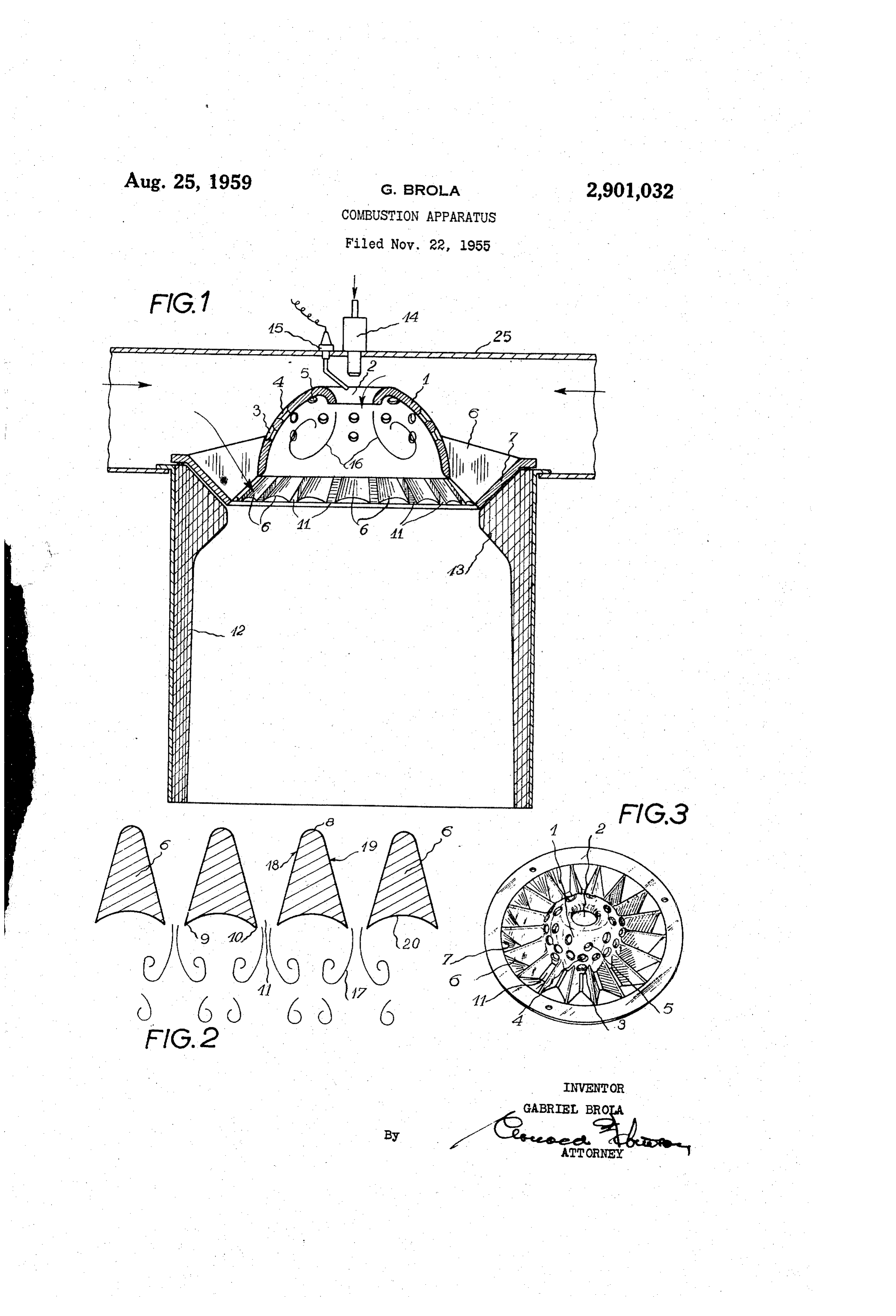
The quantity of heat developed per unit sectional area state of ignition. Increase of the combustion rate de of a combustion chamber is substantially proportional to 25 creases, the length of the flame and thus again results in a decrease in the longitudinal dimension of the chamber the volume of the combustion gases therein, or otherwise required to ensure complete combustion. stated, to the product of the combustion rate and the total The above and further objects and features of the area of the flame front of the combustion gases. Objects invention will be made clear from the ensuing descrip of the invention, accordingly, are to increase both the tion, in which one exemplary embodiment of combus rate of combustion and the flame front area in order to 30 tion apparatus according to the invention is illustrated increase the amount of generated heat. Further ob with reference to the accompanying drawings, wherein: jects are to provide improved combustion apparatus in Fig. 1 is an axial cross sectional view of the improved which the fuel injecting and ignition means are located combustion apparatus;
outside the combustion chamber and are hence protected from the high temperatures prevailing therein. Further 35 thereof; a cross-sectional developed view of the fins objects are to preheat the combustion air, increase the Fig. 3 is an overhead perspective view of the apparatus; combustion temperature, and promote the cooling of the In the illustrated embodiment, the improved combus walls of the combustion apparatus, using for this purpose tion apparatus comprises a concave shell 1 made of any the simultaneous effects of combustion airflow, radiation, suitable highly-refractory material, and formed with an and conductivity effects. Further objects will appear as 40 axial opening 2 around which the shell wall curves in the description proceeds. wardly to provide a nozzle-like entrance. The shell 1. According to the principal aspect of the invention, lim may have any suitable configuration in axial cross section proved combustion apparatus comprises a concave shell e.g. , it may be approximately hemi-spherical or : para member, means for discharging fuel and air into said shell boloidal. At spaced points through the wall of the shell member and for ignition of said fuel, means defining there are formed a plurality of ports such as 3,4, 5 which an annular wall coaxial with the shell member and are preferably provided with flared or chamfered ends spaced from the periphery thereof, and a plurality of outwards of the shell. Formed integrally with or...con angularly spaced finlike elements interconnecting the shell nected periphery with said annular wall and defining auxiliary a set ofto outwardly the outer marginal area of the shell member are projecting fins 6, the outer ends of air inlet passages between said elements. 50 which are interconnected by a circular annulus or rim The shell member may be formed with an axial main 7 having a generally frustoconical outer surface as shown. air inlet aperture having reentrant side walls defining The fins 6 are illustrated in developed cross sectional a convergent inlet nozzle for imparting a high velocity view of flow to the primary air entering the chamber through has a ingenerally
Fig. 2, from which it will be seen that each fin triangular cross sectional shape in planes said inlet. The fuel is injected axially of this inlet, and generally parallel with the outer conical surface of the rim the fuel injector nozzle and associated ignition device can 7. The apices 8 of the fins, i.e. their upper ends as seen thus be located outside the chamber due in particular to in Fig. 1, are rounded, while their bases 20, i.e. their the high flow velocity, whereby the flame is prevented lower ends according to Fig. 1, are concave and are de from moving back toward the injector nozzle outlet. The fined by sharp edges or apices 9 and 10. shell is formed with space ports therein for supplying 60 The assembly comprising the shell 1, fins 6 and rim 7 secondary air, and these ports are preferably likewise formed with an inwardly convergent shape. The fin-like isrefractory mounted in the end of a tubular member 12 made of material, with the frustoconical outer surface of elements are preferably formed with concave base sur the rim 7 seated against a complementary frusto-conical faces directed towards the common axis of the shell surface formed in a thickened end portion 13 of the member and the annular wall member to receive and 65 tubular member, which defines a throat or restriction partly reflect back heat radiated therefrom, and said substantially on a level with the base of the fins. elements taper outwards into the auxiliary airflow, which The upper end of tubular member 12 is inserted in an sweeps past the extensive side walls of said elements, aperture formed in one wall of a conduit or casing 25 there promoting efficient withdrawal both of the part and is secured therein by any suitable means, so that the of said radiated heat absorbed by the fins, and of the outer convex side of the shell 1 projects into the inner heat transferred to said fins from the shell member by conductivity. Owing to this arrangement the tempera isspace defined between the walls of the member 25, which arranged for delivery of primary combustion air to the 3 apparatus. Mounted in the opposite wall of the member mentioned above. An extremely efficient cooling effect is 25 is a fuel injector nozzle 14 projecting axially towards obtained by the tertiary airflow supplied between the fins. the entrance aperture 2 into the shell 1, but extending At the same time the airflow is preheated, and the tem short of said aperture. Also mounted in said wall next perature within the space 12 is further increased by reflec to the injection nozzle is an ignition member or sparking tion from the concave base surfaces of the fins. plug 15 connected to a suitable source of voltage, and It will be understood that many modifications may projecting to a point adjacent the outlet of injection nozzle be made in the single illustrative embodiment described 14 forwardly thereof. The combustion apparatus op and shown herein without departing from the scope erates as follows: of the invention.
Combustion air enters the shell 1 partly through the IO What I claim is:
wide central entrance nozzle 2 and through the ports 1. In combustion apparatus, the combination of a 3, 4 and 5 to provide the primary and secondary airflow, concave-convex shell member having a centrally located respectively, and partly through the spaces 11 between axial air-inlet aperture, an injector nozzle located outside the fins 6, as indicated by an arrow in Fig. 1, to provide of said shell member at the convex side of the latter and a tertiary airflow. The primary air drawn in through the aligned axially with said air-inlet aperture for injecting central aperture 2 becomes mixed with the pulverized divided fuel into said shell member through said air inlet fuel from injection nozzle 14 and immediately forms a aperture, ignition means for igniting the divided fuel is combustible chargetherewith which is ignited by ignition suing from said injector nozzle, said shell member further device 15 before the charge has even penetrated the com having openings therein for the admission of secondary bustion chamber, in the area of nonturbulent, high-veloc 20 air, a frusto-conical annular wall extending coaxially ity flow determined by the entrance nozzle 2. Owing to around said shell member and spaced radially from the the high flow velocity of the combustible charge in this latter with said annular wall converging in the direction area, the flame front is prevented from moving back to in which said shell member is concave, and a plurality wards the outlet of the injector nozzle 14. It will be 25 of angularly spaced fin elements extending radially be observed that in this arrangement the injection nozzle tween said shell member and said annular wall to define and ignition device are mounted outside the combustion air-inlet passages for tertiary air between the successive chamber and are not subjected to the high temperatures elements, each of said elements being Symmetrical about developed therein, so that their service life is considerably a plane which includes at least one line extending radially lengthened. - with respect to the axis of said shell member, each of Due to the configuration of the inner shell chamber, 30 said elements increasing in thickness in the direction to and particularly due to the reentrant wall portions Sur ward the end face of the element between the small diam rounding the central aperture 2, the partially or wholly eter edge of said annular wall and the edge of said shell ignited charge entering the chamber forms a plurality of member so that said air-inlet passages are convergent in high-velocity vortices disposed in an annular array within 35 the direction of the flow of the tertiary air therethrough, the shell 1, somewhat in the manner indicated by the said small diameter edge of the annular wall extending lines 16, thereby promoting an intimate mixing of the beyond said edge of the shell member in the axial direction burning mixture with any non ignited fuel droplets that so that said end faces of the fin elements and the pas may be present, and with the secondary air entering the sages therebetween are directed toward said axis of the lateral ports 3, 4, 5. Thus the inner space of the shell 1 40 shell member, thereby to direct the flow of tertiary air becomes filled with a body of gas in substantially uniform through said passages toward a combustion Zone at the combustion which tends to project therefrom into the tubul concave side of said shell member while the flow of ter lar member 12, where the combustion continues with tiary air is rendered turbulent upon release from said con the additional or tertiary air delivered through the spaces vergent air-inlet passages at said end faces of the fin elle 11 between the fins. imentS.
It is found that the flame front becomes stabilized in 45 2. In combustion apparatus, the combination as in the area adjacent the bases of the radial fins 6. This is claim 1; wherein said end faces of the fin elements are explained by the fact that the air-flow entering through concave both to promote the turbulence in the tertiary the spaces 11 divides into a plurality of vortices such as air admitted through said air-inlet passages and to ef 17 (Fig. 2) alternately directed in opposite directions, ficiently radiate heat back to said combustion zone; and which act so to speak to "catch” the flame and bond or 50 tively wherein each of said fin elements has side faces of rela large area with respect to the area of the related stabilize the periphery of the flame front in that area.
However, combustion continues at a high rate within end face so that the fin elements are effectively cooled the tube 12 so that its side walls are carried by radiation by tertiary air flowing through said air-inlet passages and to a high temperature thereby further accelerating the Sweeping across said sides faces. rate of combustion within it, the combustion being com 55 pletely terminated as the gases issue from the opposite References Cited in the file of this patent end of the comparatively short tube. UNITED STATES PATENTS The array of fins 6 shaped as disclosed above perform 1,665,786 Irish ------------------ Apr. 10, 1928 an important heat exchange function. This is because the comparatively large laterial areas such as 18 and 19 60 2,411, 181 Altorfer ------------------- Nov. 19, 1946 (Fig. 2) of the fins are swept by the cool airflow from the 2,689,457 IKruppe ----------------- Sept. 21, 1954 space 25, while the smaller base areas 20 thereof are 2,693,083 Abbott ---------------- Nov. 2, 1954 directly exposed to the radiation from the burning mass, 2,701,608 Johnson ---------------- Feb. 8, 1955 and this radiation effect is enhanced by the concave 2,725,718 Sheets ------------------ Dec. 6, 1955 form imparted to said base areas as stated earlier. Thus 65 FOREIGN PATENTS the heat supplied to the shell 1 and transferred to the fins by conduction is effectively removed by the cool air 510,584 Canada ----------------- Mar. 1, 1955 Sweeping across the sides of the fins, together with the 547,338 Germany -------------- Mar, 10, 1932 heat transferred to the inner fin surfaces by radiation as 178,351 Switzerland ------------ Sept. 16, 1935
Provenance
- Collection
- Patents citing this work
- Pages
- 3
- Method
- pdftotext (the PDF's own text layer) + pdftoppm 300dpi page scans
- Patent office record
- patents.google.com →
- Source
- Google Patents citing-documents table
- Assignee
- Gen Thermique Procedes Brola S
- Published
- 1959-08-25
- Transcribed from
- patentimages.storage.googleapis.com →