

patent · US4162890A
Combustion apparatus
31 July 1979
Text
Page 1bibliographic recordscan →
United States Patent (19) 11 4,162,890 Hirose 45. Jul. 31, 1979 (54) COMBUSTION APPARATUS 3,868,211 2/1975 La Haye et al. ..................... 431/351 3,876,362 4/1975 Hirose .............. ... 431/252 75 Inventor: Yasuo Hirose, Yokohama, Japan 4,035,137 7/1977 Arand .................................. 431/15 73 Assignee: Bloom Engineering Company, Inc., FOREIGN PATENT DOCUMENTS
Pittsburgh, Pa. 194514 4/1957 Austria ..................................... 431/187 (21) Appl. No.: 792,978 2324493 12/1973 Fed. Rep. of Germany ........... 431/352 22 Filed: May 2, 1977 Primary Examiner-Carroll B. Dority, Jr. Int. C.’.............................................. F23D 15/00 Attorney, Agent, or Firm-Webb, Burden, Robinson & 52 U.S. C. .................................... 431/351; 431/115; Webb
58 Field of Search ............... 431/181, 187, 188, 115, 57 ABSTRACT 431/351; 239/424, 424.5 Fuel is injected into a combustion chamber by a central (56) References Cited burner. Combustion air is fed through an air supply
an annular plate surrounding the front end of said air 2,458,543 1/1949 Urquhart .............................. 431/188 . supply passage.
2,815,069 12/1957 Garraway ........................... 431/188 3,132,683 5/1964 Meyer .................................. 431/188 3,711,243 1/1973 Zink et al. ............................ 431/81 6 Claims, 12 Drawing Figures
Drawings
Page 2drawing sheetscan →
Page 3drawing sheetscan →
Page 4drawing sheetscan →
Page 5drawing sheetscan →
Page 6scan →
air supply passage and the combustion chamber having
COMBUSTION APPARATUS at least one restricted opening connecting the air supply passage with the combustion chamber. The restricted
BACKGROUND OF THE INVENTION opening of the baffle plate serves to increase the veloc 5 ity of the combustion air with respect to the fuel mix
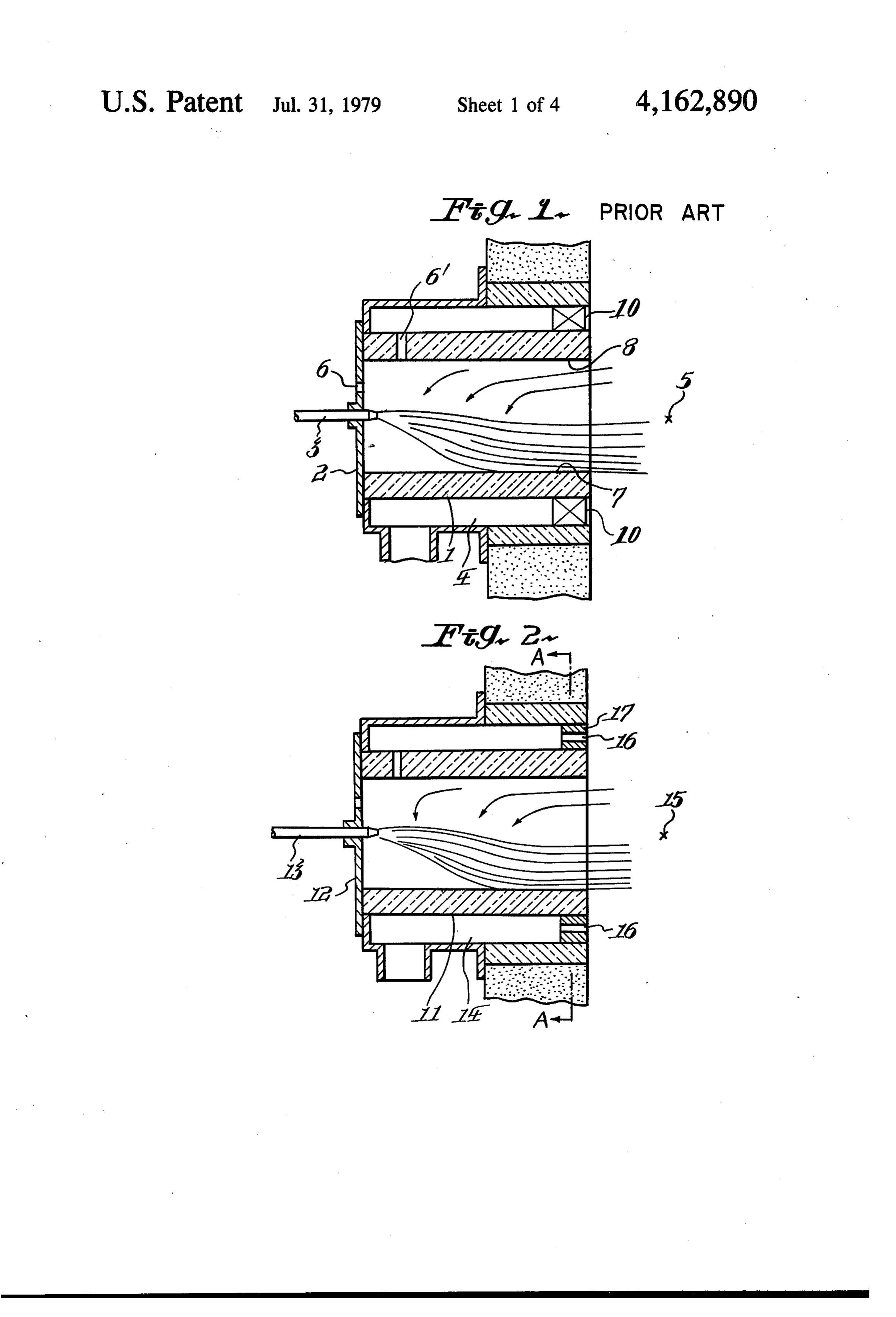
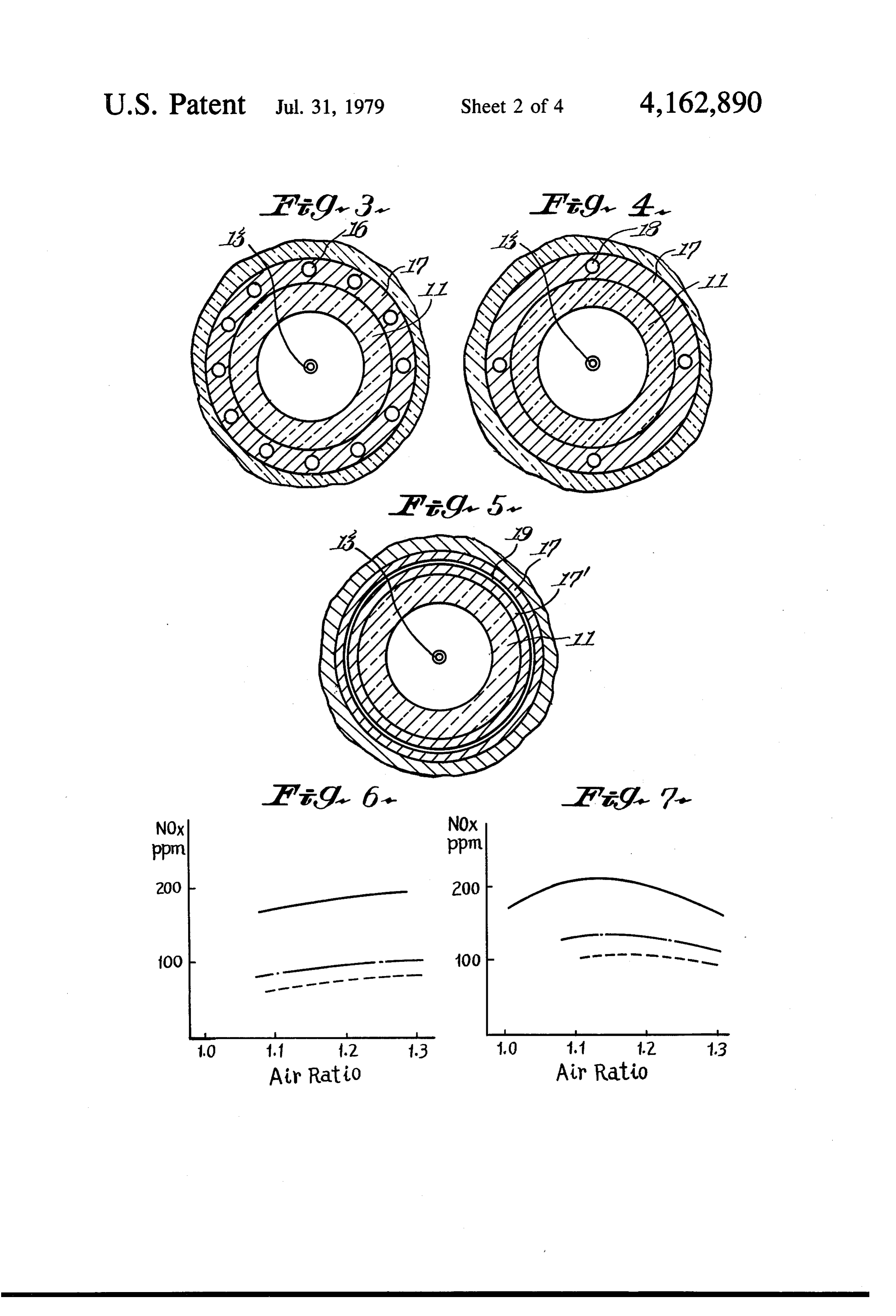
My invention is directed to a combustion apparatus ture while not increasing the proportion of fuel to air. and, more particularly, to a combustion apparatus used Thus, mixing is delayed, the burning rate is reduced, to heat furnaces and the like by burning gas or oil in a manner that results in a reduced amount of oxides of and the counterflow of unburned gases is increased, nitrogen in the products of combustion. promoting endothermic gasification of the fuel mixture Industry's increased awareness of the harmful effects 10 and decreasing the formation of NOx. of oxides of nitrogen (hereinafter "NOx”) and the strin BRIEF DESCRIPTION OF THE DRAWINGS gent requirements set by government environmental agencies regarding the amount of this pollutant that can FIG. 1 is a side sectional elevation showing a com be emitted by a furnace into the atmosphere have cre 15 bustion apparatus for practicing the combustion method ated a demand for furnace combustion devices that burn developed precedently by the present inventor. fuel so that the exhaust gases contain low amounts of FIG. 2 is a side sectional elevation of the combustion NOX. To achieve this reduction, it is desirable to burn a apparatus of the present invention. rich fuel mixture in a low temperature flame while recy FIGS. 3, 4 and 5 are sections of the combustion appa cling the unburned mixture. ratus according to the present invention taken on line As will be described below in greater detail, my com 20 A-A. in FIG.2, as viewed from the furnace side, the bustion method claimed in U.S. Pat. Nos. 3,876,362 and outlet of the combustion air supply passage 14 being 3,954,382 utilizes a rich fuel mixture and a low tempera remolded as shown in the figure.
ture flame to reduce the levels of NOx in the products FIGS. 6 and 7 are graphical representations respec of combustion. The method claimed in these patents 25 tively showing NOx generating rates in the structures of comprises injecting fuel at a high velocity through a outlets of combustion air supply pipes shown in FIGS. cylindrical burner tile structure to a combustion cham ber and deflecting the stream against the inside wall of 3,case4 and 5, in the case of using city gas as fuel and in the of using Cheavy oil as fuel.
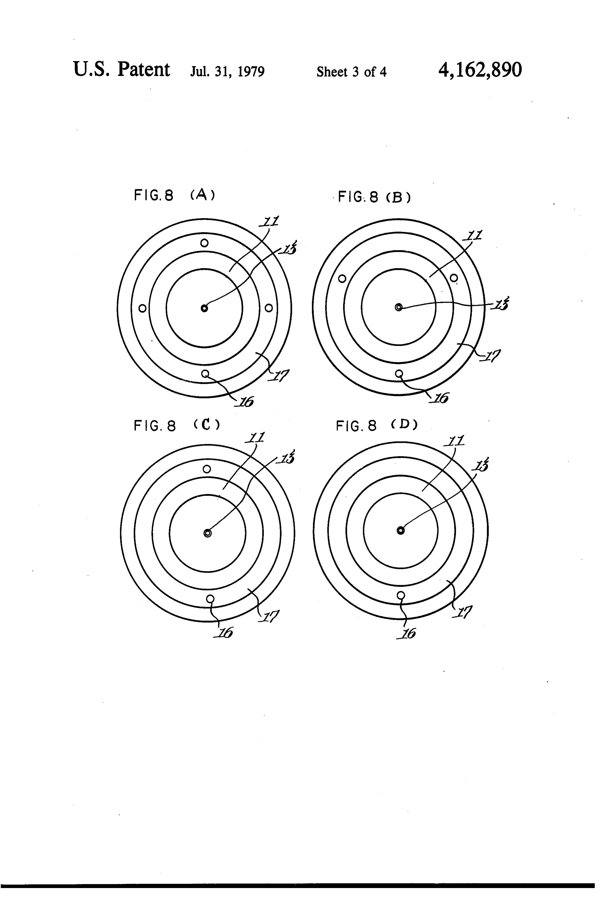
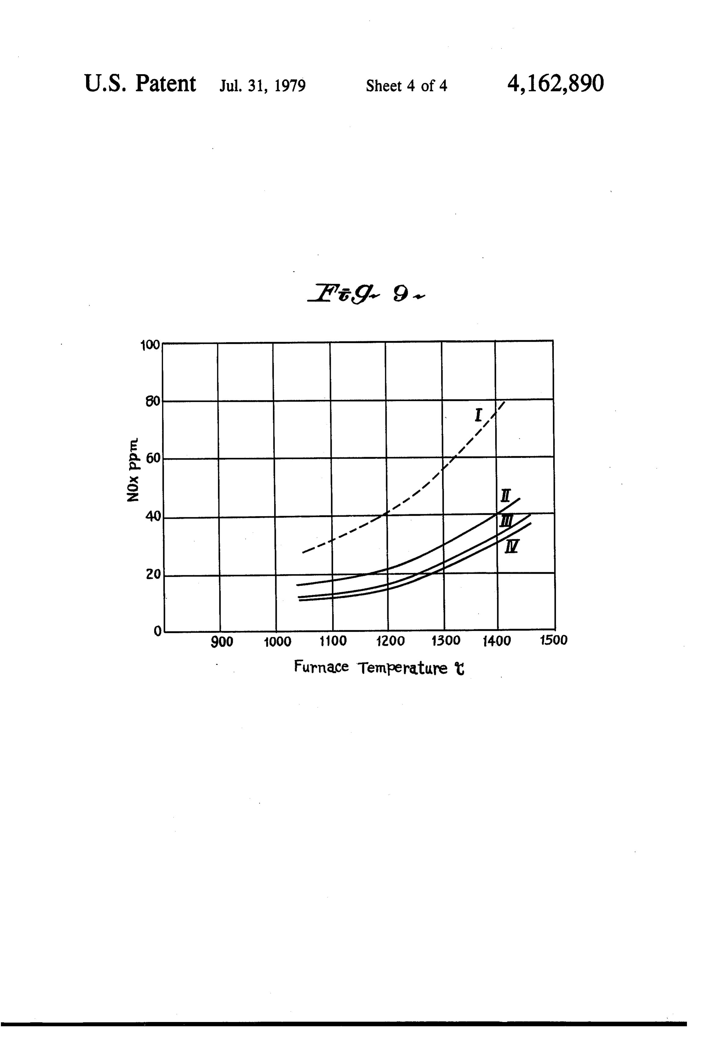
the structure, thereby causing a counterflow of high FIGS. 8A, 8B, 8C and 8D are forward elevations temperature combustion gases from the combustion 30 respectively showing the combustion apparatuses ac chamber back through the tile structure to mix with the cording to the present invention with four, three and injected fuel. Air in a quantity less than theoretical air is two air ejection holes and one ejection hole, respec supplied through an annular passage to the mixture as it tively, as viewed from the combustion chamber side. enters the combustion chamber thereby promoting en dothermic gasification of the fuel before it enters the ingFIG. 9 is a graphical representation of NOx generat combustion chamber which results in the fuel rapidly apparatus(represented 35 rate by solid line) in the combustion according to the present invention, in com and completely burning at a relatively low temperature. parision thereof with NOx generating rate (represented In order to promote the mixing of the combustion air by dotted line) in the low NOx combustion apparatus with the fuel mixture, vanes are placed in the passage according to the basic invention. supplying the combustion air to the combustion cham ber so that the air enters the combustion chamber in a 40 DETAILED DESCRIPTION OF THE spinning stream. However, the apparatus of these pa INVENTION tents has the disadvantage of causing a rapid burning of the fuel mixture which restricts flame size and tends to The combustion method of the prior invention will be give it a somewhat uneven temperature. described herein below with reference to FIG. 1. 45 In FIG. 1, a cylindrical burner tile 1 is closed partly
SUMMARY OF THE INVENTION or fully at the front end by a cover plate 2. A gas burner My combustion apparatus reduces the rate of NOx or an oil burner 3, injecting fuel and imparting large production by as much as half as compared to the prior momentum to the fuel jet, is secured to the plate 2, so art devices previously described. This reduction can ejected that fuel or a mixture of fuel and an atomizing medium occur with the burning of either city gas or Cheavy oil. 50 from said burner flows axially through the cy This marked reduction and the rate of NOx produced lindrical burner tile 1 at a high velocity. Primary air by my apparatus occurs because my apparatus delays supplied to the cylindrical burner tile is limited to a the mixing of the fuel mixture with the combustion air small amount not exceeding the explosion limit of fuel. and thus slows the burning of the fuel. An additional Secondary air, occupying the major part of the combus advantage of my apparatus is that it creates a larger 55 tion air, passes through a secondary air supply passage diameter, longer flame than that of prior art apparatus 4 having annular section, provided outside said cylindri so that a larger area of the furnace is placed in direct cal burner tile structure, and is supplied directly to a contact with the flame. Another advantage of my appa combustion chamber 5.
ratus is that the larger flame created is even more uni The front end of the annular combustion air passage form in temperature and thus can evenly heat the ad surrounding the cylindrical burner tile structure is joining furnace. closed. When a fuel jet having large momentum shoots My combustion apparatus comprises a combustion through the cylindrical burner, high temperature com chamber; a cylindrical tile structure attached to the bustion gas counterflows into the cylindrical burner combustion chamber at an end; a cover plate which is from the combustion chamber. High temperature com attached to the tile structure at an opposite end; a means 65 bustion gas which has counterflowed in said cylindrical forming an air supply passage adjacent the tile struc burner tile structure is sucked up quickly in the fuel jet ture; an inlet from the air supply passage through the and is consumed. Hence, high temperature combustion tile structure; and a baffle plate positioned between the gas continuously counterflows.
Page 7scan →
High temperature combustion gas which has been The structures shown in FIGS. 3, 4 and 5 increase air sucked up in the fuel jet is uniformly diffused, thereby velocity from the conventional 10 m/sec or less to from promoting a quick endothermic gasification reaction 30 m/sec to 100 m/sec, whereby the spinning stream of with the fuel. Since the partially burnt gas produced by combustion gas is mixed vigorously at the outlet of the this endothermic gasification reaction contains reduced 5 burner tile structure, and this spinning stream is reintro H2 or CO in large quantities, the gas easily can be ig duced considerably vigorously into the burner tile nited and burnt when it arrives in the combustion cham structure. Accordingly, combustion gas can be caused ber 5. There the gas is supplied with secondary air and to counterflow into the burner tile structure more eas it rapidly flames. The flame thus produced has an ideal ily, and endothermic gasification reaction is accurately temperature distribution without forming any partial 10 carried out, and NOx generating rate can be further high temperature portion. As a consequence, NOx gen remarkably reduced.
erating rate can be remarkably reduced as compared FIG. 2 shows a combustion apparatus in which the with conventional combustion. furnace end of the air supply passage 14 is fitted by an As a result of tests, it has been found that the amount annular baffle plate 17. Said baffle plate 17 has holes 16 of high temperature combustion gas counterflowing 15 formed therein.
into the cylindrical burner tile structure 1 can be in FIG.3 shows abaffle plate 17 having twelve holes 16. creased to about 60% of the amount of air for theoreti To maintain the proper proportions of combustion air cal combustion, and further the gas can be caused to and fuel mixture during the operation of this embodi counterflow at all times in a substantially constant ment of the invention, the velocity of the combustion amount. This is possible by Coanda Effect caused gen 20 air should be approximately 30 m/sec. erally by the high velocity stream within the cylindrical FIG. 4 shows another combustion apparatus in which burner tile 1. To facilitate occurence of Coanda Effect, the forward end of the air supply passage 14 is fitted by the outer annular front end of the cylindrical burner the baffle plate 17 which has four holes 18 formed structure 1 is closed by the plate 2, and air stream inlets 25 therein. To maintain proper proportions of air and fuel, 6 and 6 are provided in said plate and in said cylindrical the velocity of the combustion air for this embodiment burner tile structure. A fuel jet having large momentum should be approximately 90 m/sec.
is passed through the cylindrical burner tile 1. The fuel FIG. 5 shows still another combustion apparatus in jet is constantly deflected towards the inner side wall 7 which cylindrical sleeves 17 and 17" are secured to the opposite to said air inlet 6' and advances along said 30 forward end of the air supply passage 14 (as shown in inner side wall 7, while being interfered with by said FIG. 2). Air is injected through a space 19 having a inner side wall 7. When the Coanda Effect is thus stabi width about 1/5 that of the conventional apparatus and lized on the specific side wall 7, counterflow of high formed between these sleeves. The velocity of air being temperature combustion gas is facilitated along the selected to be about 100 m/sec.
opposite side wall 8. Furthermore, the fuel jet interfer 35 FIG. 6 is a graphical representation showing the case ence with side wall 7 promotes vigorous diffusion and of using city gas as fuel. FIG. 7 is a graphical represen endothermic gasification reaction, and the amount of tation showing the case where C heavy oil is atomized high temperature combustion gas becomes large and is by steam and injected. In both graphical representations maintained at a constant value at all times. there are shown the results of the tests by representing As a result of tests, it was discovered that the endo 40 the values of the combustion apparatus shown in FIG. 3 thermic gasification reaction occurred within the cylin in solid lines, the values of the combustion apparatus drical burner tile 1, and the resulting mixture was sup shown in FIG. 4 in chain lines with consecutive dots, plied to the combustion chamber 5, whereby complete and the values of the combustion apparatus shown in combustion of fuel could be performed at an excess air FIG. 5 in dotted lines.
ratio less than the conventional general excess air ratio, 45 As shown in the graphical representations of FIGS. 6 for instance, at an air ratio of As 1.1. Since the thus and 7, even in the case of using heavy oil as well as city obtained flame did not form local high temperature gas as fuel, according to the combustion method devel portions, it was found that NOx generating rate was oped by the present invention, when air velocity is reduced remarkably by half lower than that of the con increased, that is, when air in a required amount is sup ventional method, and the soot generating rate was also 50 plied through a slit formed to be as narrow as possible, be reduced. NOx tends to decrease and the degree of reduction is As a result of repeating various tests for improve considerably large.
ments in the basic low NOx generating combustion The preferred embodiment of the invention is de apparatus, it has been found that the NOx generating picted in FIGS. 8A, 8B, 8C, and 8D. In the baffle plate rate can be reduced even further. 55 17 on the furnace end of said secondary air supply pas The first improvement resides in that the sectional sage, as shown in FIGS. 8A, 8B, 8C and 8D, air ejection area of said air supply passage is narrowed at the fur holes 16 are formed in numbers of four, three, two and nace end of said air supply passage 4 provided outside one, respectively.
the cylindrical burner tile structure 1 thereby accelerat In the combustion apparatus relating to the basic ing the injection velocity of air from 10 m/sec to be invention (FIG. 1), supply of combustion air from the tween 30 and 100 m/sec m as compared with that of the air supply passage 4 is performed in such a manner that conventional apparatus, whereby the occurrence of the the air supply passage 4 is provided at its forward end spinning stream at the outlet of said cylindrical burner with a rotary vane 10 rotating to discharge whirling air tile structure is promoted and counterflow of combus surrounding annularly the entire circumference of the tion gas into said burner tile structure is activated. As a 65 partially burnt gas flowing from the cylindrical burner result, NOx generating rate is reduced by about half as tile 1. The circumference of the partially burnt gas is compared with the basic low NOx combustion appara substantially surrounded by a large number of air jets at tuS. air velocities of 10 m or less per second. The partially 8 burnt gas is rapidly brought into contact and mixed be made without departing from the scope of the inven with air, and burns. tion, which is defined in the following claims. However, the combustion apparatus according to the I claim:
preferred embodiment of the present invention, only a 1. A combustion apparatus comprising: very small number of air injection holes are formed. 5 A. a combustion chamber;
Partially burnt gas near said air jet comes into contact B. a tile structure having inner and outer side walls, with air and rapidly burns, but the partially burnt gas said inner side wall defining an interior cavity of remote from the air jet has no chance to come into said tile structure, and an end communicating with contact with air and mix therewith. Contact mixing said combustion chamber;
between gas and air is delayed, and combustion is thus O C. a disk-shaped cover plate attached to an opposite delayed. Hence, the flame obtained has a large diame end of said tile structure; ter, and its length is elongated, thus becoming larger D. an annular air passage adjacent said outer side wall than the flame of the basic apparatus. Furthermore, this of said tile structure and connected to a source of flame does not partly form particularly high tempera air above atmospheric pressure; ture portions (so-called "hot spots”) and burns more 15 E. a burner means extending through said cover plate slowly than that obtained by the combustion apparatus and positioned so that it directs a stream of fuel at according to the basic invention, as a result of which a velocity sufficient to create a Coanda effect axi NOx generating rate is further reduced as compared ally through said interior cavity to said combustion with the low NOx combustion apparatus according to chamber whereby combustion gases are drawn the basic invention. 20 back through said interior cavity to mix with said FIG. 9 is a graphical representation showing the stream of fuel;
reduction of NOx generating rate by the combustion F. an air stream inlet on one side only and in said tile apparatus according to the preferred embodiment of the structure connecting said air passage to said inte present invention in comparison with that by the low rior cavity and positioned so that combustion air in NOx generating apparatus according to the basic inven 25 an amountless than that necessary to burn said fuel tion. In FIG. 9, the axis of coordinates represents O2 stoichiometrically enters said interior cavity in a 11% converted NOx PPm and the axis of abscissae direction normal to said stream of fuel and stabi represents the furnace temperature in degrees centi lizes the position of said stream of fuel along a grade. NOx generating rates of the combustion appara portion of said inner side wall opposite said air tus according to the basic invention in respective fur 30 stream inlet; and nace temperatures are represented by dotted line I, and G. a baffle plate placed between said annular air sup Nox generating rates of the combustion apparatus ac ply passage and said combustion chamber, said cording to the preferred embodiment of the present baffle plate having one or more air jets passing invention in the case of providing four air injection therethrough connecting said air passage to said holes by solid line II, in the case of providing three air 35 combustion chamber, at least one of said jets being injection holes by solid line III, and in the case of pro located on substantially the same side of said tile as viding two air injection holes by solid line IV. said air stream inlet, whereby combustion air is Tests according to the above described graph were supplied to said combustion chamber at a velocity performed using city gas as fuel. The amount of fuel of not less than about 30 meters per second. used was 1,800,000 KCal/hr., air ratio A= 1.1. The tem 2. The combustion apparatus of claim 1 wherein said perature of supplied air was 400 C., and the motive air one or more air jets comprises not more than four air of the burner was 8%. NOx generating rate in the com ejection holes each of a size such that the velocity of bustion apparatus according to the present invention is said combustion air entering said combustion chamber reduced by about half as compared with NOx generat through said holes is not less than about 90 meters per ing rate in the combustion apparatus according to the 45 second.
basic invention. 3. The combustion apparatus of claim 2 wherein said Although the above description was made with re one or more air jets supply air to the combustion cham spect to the data of gaseous fuel, NOx generating rate is ber in an amount exceeding that needed for theoretical reduced similarly with respect to the case of using combustion by about 10 percent.
heavy oil fuel. 50 4. The combustion apparatus of claim 1 wherein said Furthermore, it is not always necessary to arrange the cover plate has a second air stream inlet which connects air ejection holes respectively at symmetric positions said interior cavity to an air supply. with respect to the center. The holes can be arranged 5. The combustion chamber of claim 1 wherein said deflectively toward the side wall which must be pre tile structure is cylindrical in shape. ponderantly heated in the furnace, with the heating 55 6. A combustion apparatus comprising: efficiency being rather improved. A. a combustion chamber;
Although it has been described above that the present B. a tile structure having inner and outer side walls, invention is applied to the combustion apparatus ac said inner side wall defining an interior cavity of cording to the basic invention, the present invention is said tile structure, and an end communicating with not limited to the combustion apparatus according to said combustion chamber;
the basic invention it can be applied for various combus C. a disk-shaped cover plate attached to an opposite tion apparatuses each have a burner at the central part end to said tile structure; and combustion air is supplied from the circumference D. an annular air supply passage adjacent said outer of said burner. Even in this case, the effect of remark side wall of said tile structure and connected to a able reduction of NOx generating rate can be achieved. 65 source of air above atmospheric pressure; While the invention has been described in part with E. a burner means extending through said cover plate reference to specific embodiments, it will be obvious and positioned so that it directs a stream of fuel at that modifications and variations of the invention may a velocity sufficient to create a Coanda effect axi 9 ally through said interior cavity to said combustion portion of said inner side wall opposite said air chamber whereby combustion gases are drawn stream inlet; and back through said interior cavity to mix with said G. a baffle formed of two concentric cylindircal stream of fuel; sleeves defining an annular restricted air jet slit F. an air stream inlet on one side only and in said tile therebetween connecting said air passage to said structure connecting said air passage to said inte rior cavity and positioned so that combustion air in combustion chamber whereby combustion air is an amount less than that necessary to burn said fuel supplied to said combustion chamber through said stoichiometrically enters said interior cavity in a slit at a velocity of not less than about 100 meters direction normal to said stream of fuel and stabi O per second.
lizes the position of said stream of fuel along a
Provenance
- Collection
- Patents citing this work
- Pages
- 9
- Method
- pdftotext (the PDF's own text layer) + pdftoppm 300dpi page scans
- Patent office record
- patents.google.com →
- Source
- Google Patents citing-documents table
- Assignee
- Bloom Engineering Company, Inc.
- Published
- 1979-07-31
- Transcribed from
- patentimages.storage.googleapis.com →