

patent · US3207204A
Fuel burner controls
21 September 1965
Text
Drawings
Page 1drawing sheetscan →
Page 2drawing sheetscan →
Page 3drawing sheetscan →
Page 4scan →
United States Patent Office 3,207,204 Patented Sept. 21, 1965 is not established after a predetermined time interval.
FUEL BURNER CONTROLS The second combustion switch is connected in series cir Paige W. Thompson, Morrison, Ill., assignor to General cuit relation with the igniter. Further, the igniter and the Electric Company, a corporation of New York Second combustion switch are connected in series in a Filed Sept. 13, 1963, Ser. No. 308,897 starting circuit branch connected across the supply ter 6 Claims. (C. 158-128) minals, and a gas valve control coil is connected in paral lel circuit across the starting circuit branch. The lock
This invention relates to fuel burner controls and more out and relay switches are joined in series circuit be particularly to an improved control for automatically ig tween the operating circuit branch and the starting cir initing and controlling the operation of a gas burner. O cuit branch and in circuit with one of the supply ter In the type of controls used for operating fuel burners, minals so that when either of these switches are in the for example, the master control used to operate the gas Open position, the power to the igniter and the gas valve burner in a clothes dryer, space heater and other gas control coil is interrupted.
fired equipment, it is necessary that some means be With the safety lockout heater connected in series cir provided for shutting off the supply of gas in the event 5 cuit relation with the hold resistor and the main relay the burner flame is extinguished or if ignition of the gas coil, the control causes the fuel burner system to fail fails to take place. Generally, in the event of such Safe in the event that the safety lockout heater or the failures, the control will allow the gas or other fuel to be connections thereto fail. This safety feature is accom supplied to the burner for a predetermined interval and plished without the need for additional components, such if ignition does not occur within the interval, the control 20 as switches and the like.
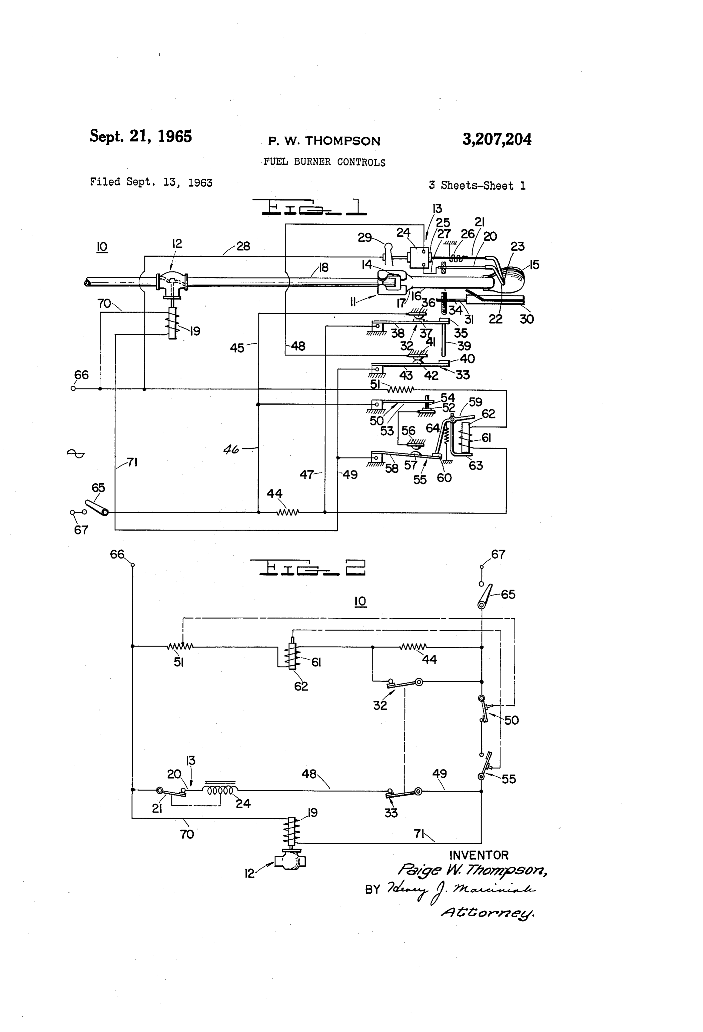
will cause the supply of the gas to be shut off to prevent Further aspects of the invention will become apparent dangerous accumulations of gas. from the more detailed description of the invention which A commonly used control for a gas burner employing follows. It will be understood that the specification con electric ignition, utilizes a safety lockout switch, which cludes with claims which particularly point out and dis is operated with a delayed action by a lockoutheater con 25 tinctly claim the subject matter which I regard as my in nected in parallel with a hold resistor. The safety lock vention. The invention, however, both as to organiza out switch comes into play to cut off the power to the tion and method of operation, may be best understood solenoid or coil of the gas valve, when the gas fuel is with reference to the following description taken in con not within a permissible interval, initially ignited, or re nection with the accompanying drawings in which: ignited after a flame failure. Such conventional controls 30 FIGURE 1 is a diagrammatical view of the improved control embodying one form of the invention particularly do not usually cause the system to fail safe, i.e., shut off adapted the power to gas valve solenoid and to the igniter, when for a gas burner application, the switches being the connections to the safety lockoutheater or the lockout shown in their normal position for the “cold” condition heater itself fails during the operating condition of the of the control;
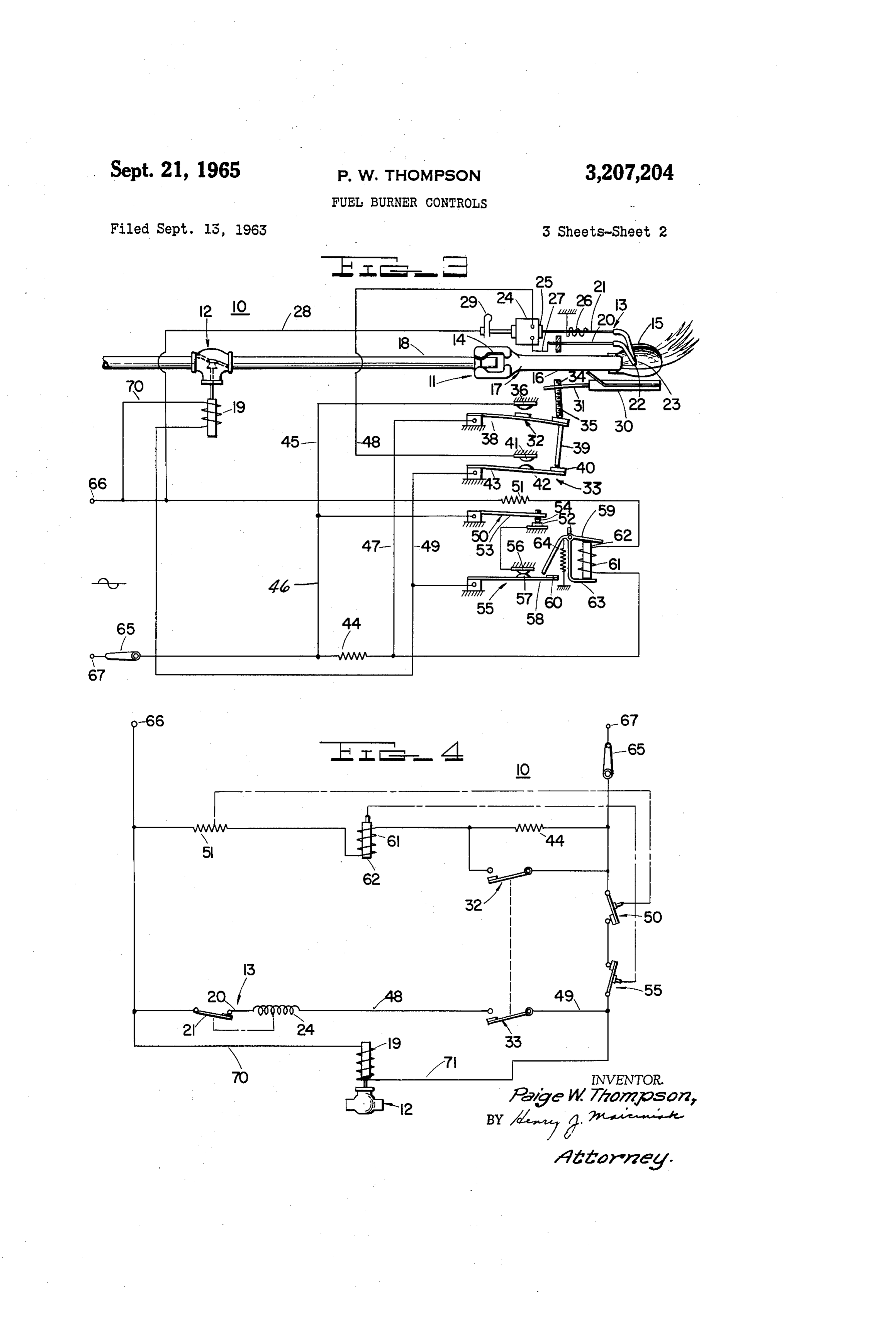
fuel burner. It is particularly desirable that a control FIGURE 2 is a simplified circuit diagram of the control for a fuel burner cause the system to completely fail safe illustrated in FIGURE 1 with the components of the con when such failures occur. trol shown schematically and arranged to more clearly Accordingly, a general object of the present invention illustrate the relative circuit connections between the is to provide a control for operating a fuel burner incor 40 components;
porating improved safety features. FIGURE 3 is a diagrammatical view of the control A specific object of the invention is to provide a fuel corresponding to the view shown in FIGURE 1 and show burner control that will cause the system to fail safe in ing the relative positions of the switches when the con the event that the lockout heater or connections thereto trol is in the “hot” or operating condition; fail. FIGURE 4 is a simplified circuit diagram of the con It is another object of the present invention to provide 45 trol corresponding to FIGURE 3 with the components an improved fuel burner control that utilizes components of the control shown schematically and arranged to more that are relatively simple and inexpensive in construction the clearly illustrate the relative circuit connections between components;
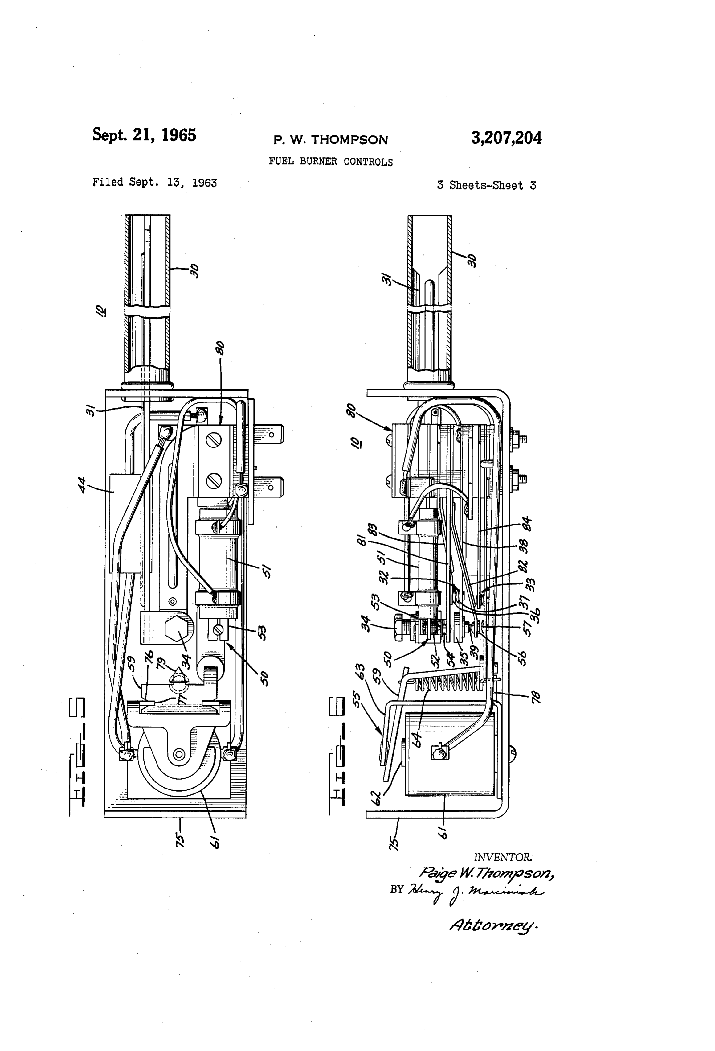
and that insure safe operation of the burner.
In accordance with one form of my invention I have FIGURE 5 is a plan view of the control with the cover provided an improved control for use in conjunction with 50 plate removed to show the physical arrangement of the a fuel burner, a fuel control valve and an electrical ig components; and m niter. The control includes a safety lockout heater for FIGURE 6 is a side elevational view of the control cor actuating a lockout switch, a main relay coil for operating responding to the view shown in FIGURE 5. a normally open relay switch and a hold resistor for limit Referring now in more detail to the drawings, I shall ing the current to the relay coil to a value above its hold 55 now more particularly describe the improved control 10 ing current value but below the value required to activate as applied to a gas burner 11 having associated there the safety lockout heater. The lockout heater, the relay with a solenoid operated valve 12 and an igniter 13. The coil and the hold resistor are connected in series circuit gas burner 11 includes the adjustable air intake openings relationship in an operating circuit branch. The operating 14, a reflector 15, and an essentially tubular chamber 16 circuit branch is connected in circuit across the supply 60 formed with a narrow throat section 17. terminals or connections provided for energization from Gaseous fuel is admitted to the burner 11 by a gas an alternating current source. inlet pipe 18 which projects into the gas burner 11 through In order to detect the presence or absence of combus an opening provided at the end thereof. A controlled tion, I have provided a combustion responsive means supply of air is admitted to the burner 11 through the ad which actuates a first and a second normally closed com 65 justable air intake openings 14. During operation of the bustion switch to an open condition when combustion is burner 11, a mixture of the gaseous fuel and air is con established. One of the combustion responsive switches ducted through the chamber 16, which functions as a is connected across the hold resistor to provide a shunt venturi tube, and the mixture of air and fuel is ignited path so that the current to the relay coil and lockout in the vicinity of the outlet by the igniter 13. heater will be at a level sufficient to actuate the relay 70 The supply of gaseous fuel is controlled by an elec coil, and to activate the lockout heater if combustion tromagnetically operated gas valve 12 which is opened 5 by energizing gas valve control coil 19. When the coil 50. It will be understood, as will hereinafter be more 19 is deemergized or when the current through the coil fully explained, that when the hold resistor 44 is not 19 falls below the holding value, the valve 12 returns short-circuited, the current supplied to the lockout heater to the closed position by gravity, a spring or other suitable 51 is insufficient to actuate the lockout switch 50. bias means (not shown). W A main relay switch 55, which is normally in an open - In order to initiate combustion of the fuel, a pair of position when the control 10 is in the "cold' condition, electrodes 20, 21 of the igniter 13 have their igniter tips is almost instantaneously closed when the control switch 22, 23 disposed near the burner outlet in proper location 65 is closed in response to a demand for combustion. The with respect to the fuel stream. It will be seen that elec Switch may be a thermostat, a timer or other switching trode 20 is fixed while the other electrode 21 is arranged O means. The type of switch employed, will, of course, for relative rotational movement with respect to the fixed depend upon the particular application of the control 10. electrode 20. The movable electrode 21 is driven by the The relay switch 55 includes a relatively fixed contact 56 armature 25 and oscillated at a relatively low frequency and a movable contact 57 carried near the free end of the when the igniter coil 24 is energized. Further, it will be flexible strip 58, a pivotally supported operating arm or noted that the movable electrode 21 is biased by a spring 5 armature 59, a push button 60, a relay coil 61, a core 62 26 to a normally closed position. An electric arc is gen and a support bracket 63. The operating arm 59 is erated between the igniter tips 22, 23 as the movable elec normally biased by a spring 64 to hold the relay switch trode 21 is intermittently rotated out of engagement with 55 in a normally open position when the relay coil 61 the fixed electrode 20. The fixed or stationary electrode is not energized or when the current through the relay 20 is connected in electrical circuit with the coil 24 by 20 coil 61 falls below the holding current value of the relay means of a connection 27 and the movable electrode 21 Switch. The relay coil 61 used in the exemplification of is connected in electrical circuit with lead 28 through the the invention had a pick-up value of .095 ampere and a contact 29 to join the electrodes 20, 21 in series circuit holding current value of .035 ampere. As will herein relation with the igniter coil 24. The spring force exerted after be more fully described in connection with the by the spring 26, the inertia of the armature-electrode 25 description of the operation of the circuit, an open cir mass system, and the torque developed by the armature cuit type of failure in the lockout heater 51, the relay 25 are the factors that determine the frequency at which coil 61 or the hold resistor 44 will cause the relay switch the igniter tips 22, 23 are opened and closed during the 55 to be deemergized and restored to its normally open ignition period. A frequency of approximately 10 cycles position.
per second provides satisfactory ignition in the illustrated 30 Supply terminals or connections 66, 67 are provided application. for energization from a suitable alternating current supply, The combustion responsive means used in the exem Such as a 120 volt, 60 cycle supply. In the exemplifica plification of the invention includes a flame detector tube tion of the invention terminal 67 was adapted for connec 30 positioned in proximity to the burner 11, an operating tion to the ungrounded or black lead of the power sup arm 31 and a pair of combustion switches 32, 33. The 35 ply.
presence of the gas flame near one side of the tube 30 Having more specific reference now to the simplified results in a temperature differential between one side and schematic circuit diagrams of the control 10 as shown in the other, which causes the flame detector tube 30 and FIGURES 2 and 4, I will now more fully describe the the operating arm 31 to deflect to the position shown in circuit connections of the components of the control 10. FIGURE 3. When so deflected, the operating arm 31 40 The lockout heater 51, the relay coil 61 and the hold actuates the first combustion switch 32 and the second resistor 44 are connected in series circuit relation with combustion switch 33 to the open position. It will be seen each other in the first or operating circuit branch which that an adjustable screw 34 carried by the operating arm is connected across the supply terminals 66, 67. It will be 31 provides a means for adjusting the position of the arm noted that the first combustion responsive switch 32 is 31 with respect to the push button 35. connected in a shunt across the hold resistor 44. Thus, Having more specific reference now to the combustion when control switch 65 is initially closed to energize the switches 32 and 33, I will now more fully describe these control 10, the hold resistor 44 is short-circuited. The Switches. The first combustion switch 32 includes a current through the operating circuit branch is essentially relatively fixed contact 36 and a movable contact 37 car limited only by the impedance of the lockout heater 51 ried near the free end of a flexible strip 38 supported 50 and the relay coil 61 and is sufficient to close the relay fixedly at the other end. A finger 39 extends downwardly Switch 55.
from the free end of the flexible strip. 38 so as to engage The igniter electrodes 20, 21, the igniter coil 24 and the push button 40 of the second combustion switch 33 the second combustion responsive switch 33 are con when the operation arm 31 is deflected. The second com nected in series in the starting circuit branch of the con bustion switch 33 includes a relatively fixed contact 41 trol 10. It will be noted that the gas valve control coil and a movable contact 42 carried on a flexible strip 43. 19 is connected across the starting circuit branch by leads The first combustion switch 32 is connected across the 70, 71. The lockout switch 50 and the relay switch 55 hold resistor 44 by leads 45, 46, 47, to short-circuit the are connected, preferably, in circuit with the terminal 67 hold resistor 44 when the switch 32 is closed. The sec between the operating and starting circuit branches, as ond combustion switch 33 is connected in the second cir 60 shown, so that when either the lockout switch 50 or the cuit branch containing the igniter 13 by leads 48 and relay Switch is open, the supply of power is interrupted 49 and opens the electrical circuit in the second circuit to the starting circuit branch and to the gas valve control branch when switch 33 is actuated to the open position. coil 19.
Thus, when combustion is established, this switch causes In FIGURES 5 and 6, I have illustrated a plan and the igniter 13 to be deemergized. 65 side view to show the physical arrangement of the com A lockout switch 50 operable by a lockout heater 51, ponents of the control 10 as employed in the illustrated interrupts the power to the gas valve coil 19 and igniter embodiment of the invention. It will be appreciated that 13 under certain conditions as will hereinafter be more these views are not intended to show the specific circuit fully discussed. The lockout switch 50 includes a rela connections. The control 10 is housed in a control box tively fixed contact 52 and a deflectable switch arm 53 70 With the cover plate (not shown) and is supported on a carrying a contact 54. In the illustrated exemplification U-shaped frame 75. It will be seen that the control or of the invention, if combustion did not take place within main relay 55 is attached to the U-shaped frame 75 at less than 90 seconds after the control 10 was energized, the left end. The relay 55 includes the relay coil 61, the the heat generated in the lockout heater 51 was sufficient core 62 disposed within the coil 61, the armature or to deflect the Switch arm 53 and open the lockout switch operating arm 59, the spring 64 and the bracket 63. The 6 operating arm 59 is pivotally carried on the bracket 63 the hold resistor 44 is not short-circuited by switch 32, by assembling the indented portion 76 of the arm 59 into the power supplied to the lockout heater 51 is not suffi a recess 77 formed in the bracket 63, as will be seen in the cient to activate the flexible strip 53 of the lockout view illustrated in FIGURE 5. The spring 64 is attached Switch 50.
at one end to a tab 78 extending from the bracket 63 and When switch 65 is opened in response to a demand for is attached at the other end to a tab 79 on the arm 59. a cessation of heating, the relay switch 55 immediately As shown in FIGURE 5, the hold resistor 44 is con opens to interrupt the supply of power to the gas valve nected to a terminal of the relay coil 61. At the right control coil 19 thereby stopping the supply of gas fuel hand side of the U-shaped frame 75 a stack 80, on which to burner 11. The absence of flame is detected by the switching elements of the control 10 are supported, is O flame detector tube 30, and after a pretermined interval attached to the frame 75. (approximately 6 seconds in the illustrated embodiment) It will be seen that the lockout heater 51 is wrapped the combustion switches 32, 33 are restored to a closed around the flexible arm 53 and is supported thereon. position. The control 10 is now ready to reply to a de The contacts 52, 54 of the lockout switch 50 are shown in mand for heat if required to do so. the closed position. Further, it will be noted that rela 5 If, when the control 10 is energized in response to a tively fixed arms 81, 82 supporting contacts 52, 56 of the demand for heat, combustion of the gas is not successfully lockout and relay switches 50, 55 are sandwiched together established within the interval in which the lockout heater in the stack 80 to provide a good electrical connection 51 is heated to a point where it causes the lockout switch therebetween. to open, the Supply of gas and ignition is turned off. In As will be seen in the view shown in FIGURE 6, the 20 the exemplification of the invention this interval was ap relatively fixed contact 36 of the first combustion re proximately between 10 and 90 seconds for maximum and sponsive Switch 32 is carried on an angled support arm minimum supply voltages. The lockout switch 50 will 83. The relatively fixed contact 42 carried on a similarly remain in the open position until the operating circuit angled support arm 84 lies under the flexible strip 38 branch of the circuit is deemergized by opening the con which carries the relatively movable contact 37 of the 25 trol switch 65. It will be appreciated that when the lock first combustion responsive switch 32. The support arm out switch 50 is open and relay switch 55 is closed, the 84 carrying the contact 42 is located under the first com Supply of power to both the gas control valve coil 19 and bustion switch 32 so that when the operating arm 31 of the igniter 13 is interrupted. Since the first combustion the flame detector tube 30 is deflected downwardly, as switch 32 is closed during this condition of the control seen in FIGURE 6, the actuating screw 34 engages the 30 10, the holding resistor 44 is bypassed and the current push button 35 and effects a displacement of the free end in the operating circuit branch is above the pick-up value of flexible strip 38 and finger 39 to thereby open the first of the relay coil. Consequently, the relay switch 55 and second combustion responsive switches 32, 33. is closed during this condition of the control 10. The flame detector tube 30 is supported in an aperture When the control 0 is in the running or operating con provided in the U-shaped frame 75 and extends out dition, as shown in FIGURES 3 and 4, and a flame fail wardly of the frame 75 so that the tube can be properly ure occurs, the temperature across the sides of the flame positioned with respect to the burner 11. When the detector tube 30 will equalize and the operating arm 31 flame detector tube 30 is heated at one side so that a will return to its "cold' position to reset the combustion temperature differential exists between one side of the switches 32, 33 to their closed position. With these tube 30 and the other side, the tube 30 warps effecting a 40 switches closed, the igniter 13 is energized to provide downward movement of the actuating screw 34. In this ignition and the hold resistor 44 is short-circuited. If manner both of the combustion responsive switches 32, combustion is established within the permissible interval 33 are actuated from a normally closed to an open posi (the time required to heat the lockout heater 51 to the tion. point where the lockout switch 50 will open), the control Referring now more particularly to the diagrams shown 0 will restore the burner 11 to its running condition. in FIGURES 1-4, I will now more fully describe the However, if combustion is not established within this in operation of the improved control 10. In FIGURES 1 terval, the lockout switch 50 opens to deemergize the gas and 2 I have shown the position of switches 32, 33, 50, 55 valve control coil 19 and the igniter 13. The control 10 and 65 for the "cold” condition of the control 10. will remain in the lockout condition until the control The control 10 is energized when switch 65 is closed 50 switch 65 is opened.
in response to a demand for heat. Initially, current flows Let us assume that the control 10 is in the runing con only in the operating circuit branch, and the path of cur dition as shown in FIGURES 3 and 4 and an open cir rent flow during an arbitrary half cycle of the alternating cuit type of failure occurs in the lockout heater 51. An supply is through the supply connection 67, switch 65, open circuit in the lockout heater 51 results in an inter combustion responsive switch 32, relay coil 61, lockout ruption in the current supplied to the operating circuit heater 51 and the supply connection 66. Since the hold branch of the control 10. Thus, the current to the relay resistor 44 is essentially short-circuited, the magnitude of coil 61 is interrupted, and the relay switch 55 is opened. the current in the operating circuit branch is now above With the relay switch 55 in the open position, power to the pickup value of the relay coil 61, and the relay switch the igniter 13 and gas valve control coil 19 is cut off. 55 closes almost instantly when the control 10 is energized 60 Consequently, the burner 11 fails safe. to supply power to the igniter 13 and the gas valve con A similar condition results if a connection to the relay trol coil 19. coil 61 or the coil 61 itself fails during the running con Normally, under these conditions the gas fuel will be dition of the control. Also, an open circuit failure of ignited. The presence of a flame in the vicinity of the the hold resistor 44 during the running condition will fame detector tube 30 will cause a deflection of the tube 65 cause the relay coil 61 to be deemergized and open the re 30, and the combustion switches 32, 33 will be actuated lay switch 55. If the failure of the hold resistor 44 to the open position as shown in FIGURES 3 and 4. occurs when the control is in the “cold' condition, the When this occurs, the power supplied to the igniter 13 control 10 when energized will cause combustion to be is interrupted to turn off the ignition, and the shunt established. However, when the combustion switch 32 path across the hold resistor 44 is opened. The hold re 70 opens, the operating circuit branch is not open-circuited sistor 44 is now effective in the operating circuit branch and the relay switch 55 opens. This will shut the gas off, to limit the level of the current flowing therein so that it but upon resetting and closing of switch 32, the device is above the holding value of the relay coil 61. In the will reignite. Upon detection of fame switch 32 again illustrated exemplification of the invention the ohmic opens and causes relay coil 61 to be deemergized. This value of the hold resistor 44 was 2200 ohms. When condition may be repeated several times until the lockout 7 resistor 5 opens switch 50. Thus, the control 10 causes being joined in a series circuit with one of the supply the burner 11 to fail safe. terminals, the gas control valve coil, and the igniter to If an open circuit type of failure occurs in the igniter thereby cause the gas control valve coil and igniter to be coil 24 during the running condition, this will have no deenergized when either said lockout switch or said relay immediate effect on the operation of the burner until switch is opened.
operation is stopped in response to a demand for a ces 2. In a control for use in conjunction with a gas burn sation of heating and the switch 65 is again closed in er; an igniter, a gas valve including a control coil, a response to a demand for heat. With an open-circuited lockout switch, a lockout heater coupled with the lockout igniter coil 24, ignition is not provided, and the combus switch to actuate said lockout switch with a delayed tion switches 32, 33 remain closed. The lockout heater O action, a relay switch, a relay coil coupled with the relay 3 comes into play and opens the lockout switch 50 to Switch to actuate said relay switch, said relay coil con cause the fuel burner 11 to fail safe. nected in series circuit with said lockout heater, a hold An open circuit type failure of the gas valve control resistor connected in series circuit with the serially con coil 19 during the running condition will cause the gas nected relay coil and lockout heater to limit the current valve 12 to close. The flame detector tube 30 quickly 5 to the relay coil to at least the holding current value of detects the absence of the flame and closes the combus the relay coil, a pair of supply connections for energiza tion switches 32, 33. Since the hold resistor 44 is now tion from an alternating current supply, a first circuit short-circuited, the lockout heater 51 takes over and ac branch connected across said supply connections and tuates the lockout switch 50 to the open position thereby including said lockout heater, relay coil and hold resistor, causing the burner 11 to fail safe. 20 a combustion responsive Switching means including at From the foregoing description of the control and its least one Switch, said switch being connected in shunt operation, it will be apparent that I have provided an im with said hold resistor, and being actuated to the open proved arrangement for safely controlling the operation position in response to the initiation of combustion, a of a fuel burner. An important advantage of the im second circuit branch connected in circuit across the proved arrangement is that if the safety lockout heater, 25 Supply connections and including the igniter coil, means the main relay coil, or their connections fail, the control connecting the gas valve coil in parallel with said second will cause the burner to fail safe. circuit branch, said lockout switch and said relay switch Although the present invention has been described by joined in series with one of said supply connections and reference to a particular embodiment thereof, it is to be said parallel connected second circuit branch and gas understood that many modifications may be made to the 30 valve coil circuit to interrupt the power to said second improved control arrangement by those skilled in the art branch and the gas valve coil when either of said lockout without actually departing from the invention. For ex and relay switches is open, whereby an open-circuit type ample, it will be apparent that other suitable forms of of failure in said lockout heater causes said fuel burner combustion responsive devices may be used to detect to fail safe.
the presence or absence of combustion. Also, it will be 3. In a control for use in conjunction with a fuel apparent to those skilled in the art that the relay coil, burner; a fuel valve including fuel valve control means, the safety lockout heater and the holder resistor can be a pair of Supply connections from an alternating current rearranged in the circuit without basically changing the Supply, a normally closed lockout switch, a lockout functional arrangement. It is, therefore, intended by the 40 heater coupled with the lockout switch to open the lock appended claims to cover all such modifications that fall ‘Out Switch when the current through said lockout switch within the true spirit and scope of the invention. remains above a predetermined level for a selected in What I claim as new and desire to secure by Letters terval, a normally open relay switch, a relay coil for Patent of the United States is: nected in series circuit relation with said lockout heater 1. In a control for use with a gas burner, a gas valve operating said relay Switch, said relay coil being con including a control coil and an igniter including an igniter and closing the relay switch when energized with cur coil, a lockout heater and a lockout Switch operable by rent at Said predetermined level, a hold resistor con said lockout heater when the current through the lock nected in series with said serially connected relay coil out heater is at a first predetermined level for a selected and lockout heater and limiting the current thereto to interval, a relay coil and a relay switch operable by the at least the holding current level of the relay coil, a first relay coil for closing the relay switch when the current 50 circuit means connecting said relay coil, said lockout through the relay is at the first predetermined level, said heater and said hold resistor across the supply connec relay coil being connected in series circuit relation with tions, a combustion responsive switching means having said lockout heater, a current limiting means connected a Switch connected in parallel with the hold resistor and, in series circuit relation with said Serially connected relay a Second circuit means connecting the fuel valve control coil and lockout heater to limit the current to a second 55 means across the Supply connections, said lockout switch predetermined level below the value required to actuate and relay Switch being connected in said second circuit the relay switch and at a value sufficient to hold the relay means to thereby cause said gas valve to be deemergized switch closed but insufficient to heat the lockout heater When either said lockout or said relay switch is in the to actuate the lockout Switch, a pair of supply terminals open position, whereby an open-circuit type of failure for connection to an alternating current supply, circuit 60 in the lockout heater or the relay coil causes said con trol to fail safe.
means connecting said serially connected lockout heater, relay coil and current limiting means in a circuit branch 4. In a control for use with a gas burner; a gas con across said supply terminals without any circuit connec trol valve including a control coil and an igniter, a lock tion in parallel with said lockout heater in the circuit out heater and a lockout switch being operable by said branch connecting said relay coil across said supply 65 lockout heater when the current through the lockout terminals, at least one combustion responsive switch, heater is held at a first predetermined level for a selected Said combustion responsive switch being connected in interval, a relay coil and a relay switch operable by the shunt with said current limiting means to cause current relay coil for closing the relay switch when the current to be provided to said relay coil and lockout heater at through the relay is at the first predetermined level, said said first predetermined level when said switch is closed 70 relay Switch being in a normally open position and said and at the second predetermined level when opened, said lockout Switch being in a normally closed position, said re combustion responsive switch being actuated when com lay coil and said lockout heater being connected in series bustion is initiated, and circuit means for connecting the circuit relation, a current limiting means connected in igniter in parallel with the gas valve control coil across Series circuit with said serially connected relay coil and the supply terminals, said lockout and relay switches 75 lockout heater to limit the current thereto to a second pre 8 determined level sufficient to hold the relay switch in whereby an open circuit type of failure of said lockout a closed position, a pair of supply connections from an heater or said relay coil causes the gas burner to fail safe. alternating current supply, circuit means connecting 6. In a control for use with a fuel burner, an igniter Said Serially connected lockout heater, relay coil and means and a fuel valve for controlling the supply of fuel current limiting means in a circuit branch across said to the fuel burner, a fuel valve control coil for opening Supply connections without any circuit connection in and closing said fuel valve, said fuel valve being opened parallel with said lockout heater in the circuit branch by energizing said fuel valve control coil and closed by connecting said relay coil across said supply connections, deenergizing the coil, and said igniter means having a combustion responsive switching means including a first electrodes and an igniter coil, said igniter coil when and second combustion switch, said combustion switches O energized causing an electrode to be actuated to provide being actuated in response to the presence of combus an electric arc for ignition, a pair of supply terminals tion, said first combustion switch being connected in by for connection to an alternating current supply, an operat pass relation with said current limiting means to cause ing circuit branch connected in circuit across the supply Current to be provided to said serially connected relay coil terminals, a starting circuit branch connected in circuit and lockoutheater at the first predetermined level when in 5 across the supply terminals and in parallel with said the closed position and at the second predetermined level operating circuit branch, a normally closed lockout when in the open position, and circuit means for connect switch, a lockout heater connected in said operating ing the igniter in series with said second combustion circuit branch to open said lockout switch in a predeter Switch and connecting said serially connected igniter and mined interval if ignition fails or does not occur, a nor second combustion switch in parallel with the gas valve 20 mally closed relay switch, a relay coil connected in series control coil across the supply connections, said lockout with said lockout heater in said operating circuit branch and relay switches being joined in series circuit with one for closing the relay switch, a hold resistor connected in of said supply connections and said gas valve control coil said operating circuit branch in series with said lockout to thereby cause at least the gas control valve to be de heater and relay coil to limit the current to the relay coil energized when either said lockout switch or said relay to a level sufficient to hold the relay switch in a closed Switch is open. position but insufficient to cause the lockout heater to 5. In a control for use with a gas burner, a gas valve in actuate the lockout switches, a combustion responsive cluding a control coil and an igniter, a pair of supply switching means having a first normally closed switch terminals for energization from an alternating current connected in shunt with the hold resistor for short-circuit Supply, a first circuit branch connected in circuit across 30 ing the hold resistor during the ignition period and a the Supply terminals, a second circuit branch connected second normally closed switch for energizing the igniter in circuit across the supply terminals and in parallel during the ignition period, said first and second switches With said first circuit branch, means for joining the gas being actuated to the open position in response to the valve control coil in parallel circuit relation across the initiation of combustion, said second switch being con Second circuit branch, a lockout switch and a lockout nected in series circuit relation with said igniter in said heater, said lockout heater connected in said first circuit starting circuit branch, circuit means for connecting the branch to open the lockout switch if ignition fails or fuel valve control coil across said starting circuit branch does not occur, a relay switch and a relay coil, said relay and including connections placing said lockout switch coil connected in series with said lockout heater in and relay switch in series circuit between said operating said first circuit branch, a hold resistor connected in 40 and starting branches and in circuit with one of said Series with said serially connected lockout heater and supply terminals, whereby an open-circuit type of failure relay coil, said hold resistor limiting the current to said in said lockout heater causes said fuel burner to fail Serially connected lockout heater and relay coil to a pre safe.
determined level, a combustion responsive switching References Cited by the Examiner means including at least one combustion switch, said 45 UNITED STATES PATENTS combustion Switch being connected across said hold re 2,761,625 9/56 Dymski------------- 158-28 X sistor to cause current to be provided to said serially 2,772,727 12/56 Schell ---------------- 158-28 connected relay coil and said lockout heater at another predetermined level when the combustion switch is closed, 2,887,152 5/59 Wilder ---------------- 58-28 means connecting the igniter in said second circuit branch, 50 3,086,583 4/63 Reichow ------------- 158-125 said lockout switch and said relay switch in series circuit 3,096,811 7/63 Gustafson ---------- 158-128 X with one of said supply terminals and said second circuit FREDERICK L. MATTESON, JR., Primary Examiner. branches to thereby interrupt the power to the igniter and gas control valve coil when either said lockout switch MEYER PERLIN, JAMES W. WESTHAVER, or said relay switch is actuated to the open position, 55 Examiners.
Provenance
- Collection
- Patents citing this work
- Pages
- 8
- Method
- pdftotext (the PDF's own text layer) + pdftoppm 300dpi page scans
- Patent office record
- patents.google.com →
- Source
- Google Patents citing-documents table
- Assignee
- Gen Electric
- Published
- 1965-09-21
- Transcribed from
- patentimages.storage.googleapis.com →