

patent · US4078878A
Fuel burner control device providing safely ignited burner
14 March 1978
Text
Page 1bibliographic recordscan →
United States Patent (19) 4,078,878 Barbour et al. 45 Mar. 14, 1978 54 FUEL BURNER CONTROL DEVICE 3,744,954 7/1973 Faulkner ............................ 43/22X PROVIDING SAFELY IGNITED BURNER is: 19.12: St.
Inventors: Stacy O. Barbour, Minnetonka;
William B. Hamelink, Richfield, both Primary Examiner-William P. O'Dea of Minn. Assistant Examiner-Larry Jones 73 Assignee: Honeywell Inc., Minneapolis, Minn. Attorney,, Agent,
Agent, or
Firm e N. FeldCa Appl. No.: 683,449 57 ABSTRACT 22 Filed: May 5,9 1976 A sequencing and monitoring control device for fuel burners is provided having a unique burner program.
51 Int, Cl.2 ..... - F23N5/24. The fuel burner is put into operation with an ignition U.S. Cl. ........................................ 431/22; 431/16; means turned Onl, along with fuel pressure and combus 431/30 tion air, but without fuel being intentionally introduced Field of Search ..................... 431/22, 5, 6, 67, 66, into the combustion chamber. This start-up procedure 431/78, 79, 30, 45, 16; 236/15 BD, 15 BG would ignite any leakage fuel. The ignition is ended and References Cited an attempt is made to sense whether a flame exists
flame exists, the system shuts down on safety. If none
was
the sequence proceeds to a preselected burner 3,086,583 4/1963 Reichow ................................ 7 sequen 3,410,310 11/1968 Ray ......... 431/3OX 3,482,922 2/1969 Blackett .................. ... 431/79 X 10 Claims, 7 Drawing Figures
Limits 8 -3 O 68
CONTRQ-LER (SHOWN AT TIME = o ess C s ss s? SA
SO s
64 V GE 55
FANFUMP).
Plot Valve
-2 ea - - -t- - - - -t- -t-J - - - - - - - - 2S —- - - - - 37 b (- CAM OPERATED SWITCH-OPEN - ex- CAM OPERATED SWITCH - close D
-- NORMALLY OPEN CONTACT
- 4 - NORMALLY close D conTAct
Drawings
Page 2drawing sheetscan →
Page 3drawing sheetscan →
Page 4drawing sheetscan →
Page 5drawing sheetscan →
Page 6scan →
detected by a flame sensor and safety circuit which then
FUEL BURNER CONTROL DEVICE PROVIDING shuts down the system and locks the system out requir SAFELY IGNITED BURNER ing manual restart after the leakage problem has been
BACKGROUND OF THE INVENTION corrected. In the event that no leakage has occurred 5 and the flame sensor does not detect a flame when none
Large sized fuel burners used in commercial and should be present, the sequence is continued with the industrial buildings, as well as, in process control have ignition transformer being energized to provide a spark for many years utilized progammers that operate pri that is allowed time to become stable before the first marily by using motor driven cam operated switches stage oil valve or pilot oil valve is opened. After the first and electromagnetic relays to provide the necessary 10 stage oil valve is opened and a flame should be present, logic and sequence for safe burner operation. Most of the same flame sensor and monitoring system monitors the programmers on the market were designed for the for the presence of flame and will shut the system down ignition of either gas burners, or of gas burners which in a safe manner if flame is not detected. subsequently were augmented by the addition of fuel The present invention provides a fuel burner control oil. Most burners which operate directly on oil utilize 15 device utilizing a programmer that has a sequence and spark ignition of the fuel oil substantially immediately monitoring mode not heretofore available for use with upon the energization of the burner. Since the advent of burners such as oil burners.
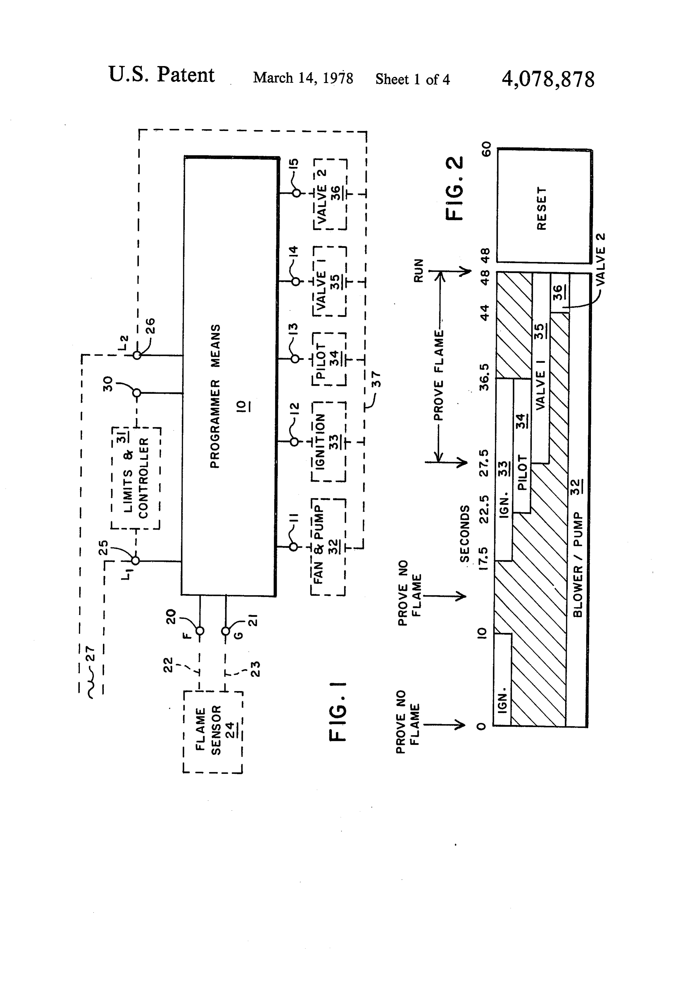
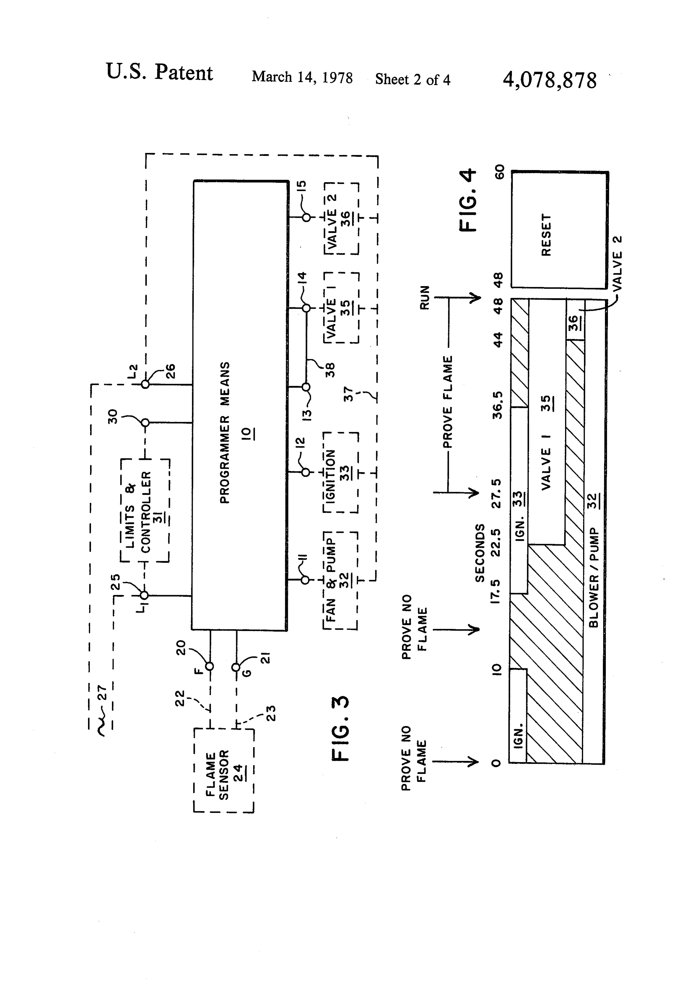
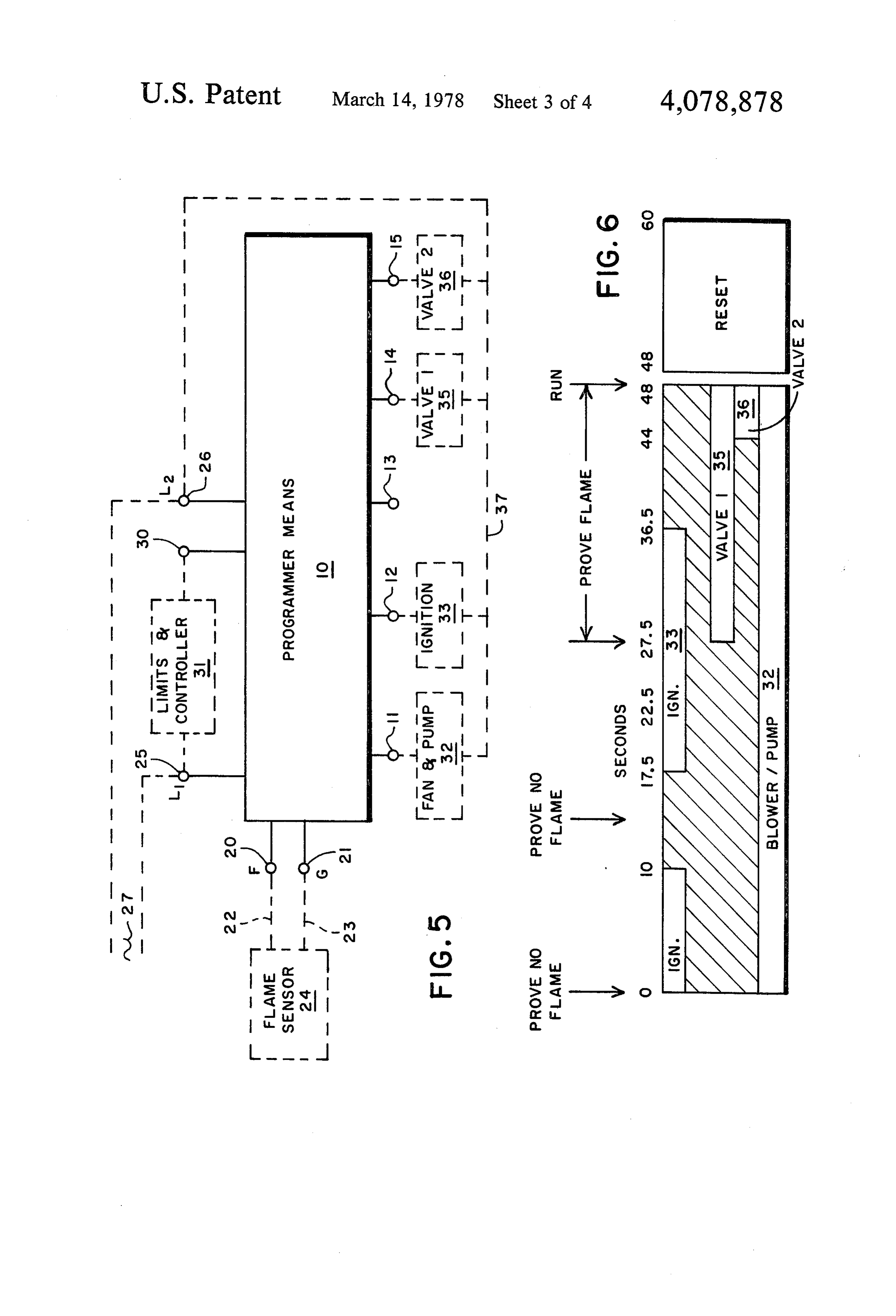
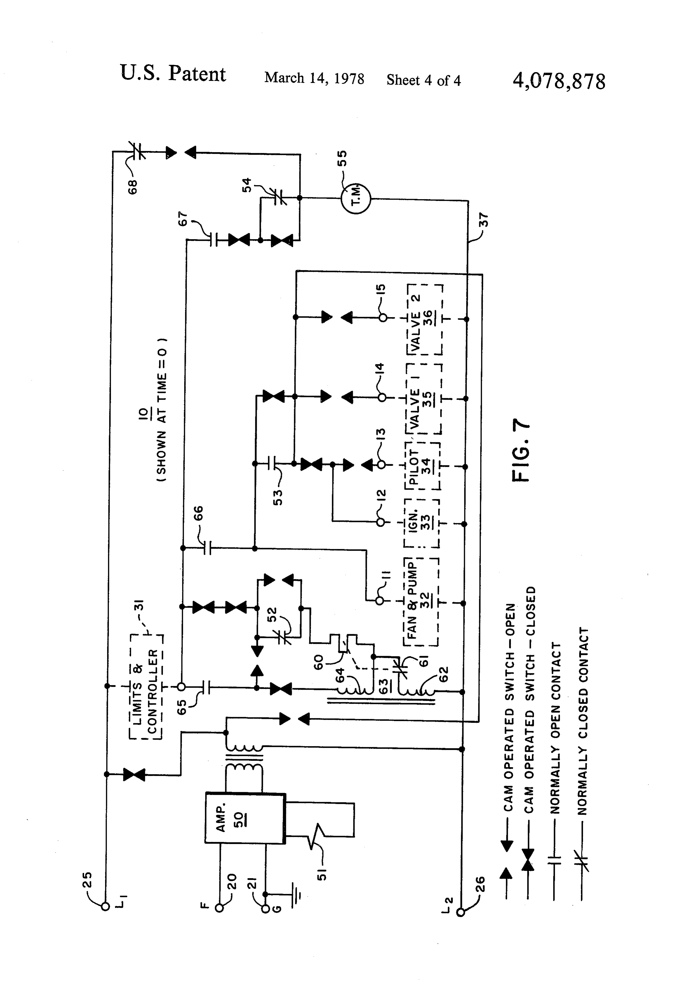
the fuel shortage, and due to changes in general eco nomic considerations in fuel burners, the oil burner has BRIEF DESCRIPTION OF THE DRAWINGS become more important. Large oil burners have sub 20 FIG. 1 is a block diagram of a fuel burner control stantially different characteristics than gas burners, and device which utilizes ignition, pilot and fuel valves, as require a different sequence for their initiation if safety well as the necessary flame sensor and input controls; is to be properly provided for. Most gas burners utilize FIG. 2 is a bar chart of the operation of the burner a prepurge period to clear the combustion chamber of control device of FIG. 1;
unburned products before the initiation of the burner 25 FIG. 3 is a block diagram of a fuel burner control cycle. This is not necessarily true of oil burners, and the device similar to FIG. 1 except the pilot has been re use of a prepurge in a oil burner can create an unsafe placed by a small first stage burner; condition by oil pressure forcing oil into the combustion FIG. 4 is a bar chart of the operation of the control chamber past a leaky oil valve and result in the accumu device of FIG. 3; FIG. 5 is a block diagram of a control lation of a dangerous amount of fuel in the combustion 30 device similar to FIG. 1 except the pilot sequence has chamber. been removed;
The special needs of oil burners, versus gas burners, is FIG. 6 is a bar chart of the operation of the control becoming more and more apparent and the provision of device of FIG. 5, and;
special equipment for oil burners for safe operation has FIG. 7 is a schematic diagram of a typical circuit of become necessary. A programmed sequence for safe 35 the main block of FIGS. 1, 3 and 5.
start-up of a gas burner may not be a safe sequence for DESCRIPTION OF THE PREFERRED start-up of an oil burner. The need of a special sequence EMBODIMENTS for oil burners has thus become apparent.
SUMMARY OF THE INVENTION In FIG. 1 there is disclosed a programming means 10 which includes a sequencing means for controlling elec
The present invention is directed to a unique se tric circuit means to a plurality of output terminal quence for a fuel burner, and more particularly a fuel means 11, 12, 13, 14 and 15. The programming means burner of the type that burns fuel oil or a similar type of has a pair of input terminals 20 and 21 which are the liquid fuel as opposed to a gaseous fuel. Fuel burners flame and ground terminals which are adapted to be that utilize liquid fuel such as fuel oil, normally include 45 connected by conductors 22 and 23 to a flame sensor a pump and a blower which supply the fuel pressure and means 24. A further pair of input terminals 25 and 26 are combustion air. The combustion air is normally allowed provided for the programming means 10 and are con to flow through the combustion chamber, but the fuel nected as the line terminals to supply an alternating oil is held out of the combustion chamber until an igni current 27 to the burner control device in general. A tion device, normally an ignition transformer with spark 50 further input terminal 30 is provided which allows for electrodes, has established a stable ignition source or the connection of various limits and controller 31 which spark. Fuel valves which are operated under the pres are conventional in fuel burner control systems. sures of modern day fuel oil burners quite commonly While the description of the system in the present have a leakage problem with the oil leaking into the disclosure is generally to fuel burners, it should be un combustion chamber prior to the establishment of a safe 55 derstood that the most common fuel burner would be an ignition spark. The present invention provides for a oil burner and that the terms generally can be consid particular cycle of operation of a fuel burner which will ered as synonymous. The programmer means 10 has its detect leakage oil and will shut down the system in a output terminal 11 connected to a fan and pump dis safe manner. closed at 32. The output terminal 12 is connected to Basically the present invention is directed to the con ignition means 33 which normally would be an ignition cept of starting the fuel oil pump and blower for com transformer and would further include ignition elec bustion air, and substantially simultaneously turning on trodes so that a spark could be generated to provide an ignition source such as an ignition transformer hav ignition of the fuel issuing into the burner. The output ing spark electrodes. The fuel oil valve is kept closed terminal means 13 is connected to a pilot valve 34, while while the ignition source attempts to light any fuel in 65 the output terminals 14 and 15 are connected to two the fuel burner that might have leaked past the fuel oil stages of oil valves 35 and 36. The fan and pump 32, the valve. If any leakage does occur, flame is brought about ignition means 33, the pilot valve 34, and the oil valves with a relatively small amount of fuel present and is 35 and 36 are all connected by a common conductor 37 7 to the terminal 26. Electric energy supplied to the ter course, brings to the attention of service personnel the minal 25 flows (in a sequence controlled manner) need for a determination of why fuel had leaked into the through the programming means 10 to the terminals 11 combustion chamber. If no flame is proved at the inter through 15 to energize the components 32, 33, 34, 35 or mediate time between 10 seconds and 17.5 seconds, the 36. programmer means 10 continues on to the 17.5 second To this point, the elements of a conventional fuel or period of time where the terminal 12 is again energized oil burner have been disclosed including the necessary to bring on the ignition means 33. The ignition means 33 programming means and the various elements that ei is allowed approximately 5 seconds to establish a clean ther supply an input signal to the programming means spark that is stable. By allowing a time interval from the 10 or are controlled as an output from the programmer O energization of the ignition means 33 certain benefits are means 10. The invention of the present application is derived. Since the ignition means 33 is generally a spark directed to the specific sequence in which these ele transformer and spark electrodes, the spark generated ments are utilized. The internal circuitry of the pro tends to clean any residual fuel on the electrodes, cleans grammer means 10 is disclosed in complete detail in any small amounts of carbon deposits, and establishes a FIG. 7 and will be referred to very briefly at the close 15 stable spark that is capable of igniting the fuel that it to of the description of the function of the programmer be introduced.
means 10. The specific circuitry contained in the pro The programmer means 10 then continues the pro grammer means 10 could be varied extensively and is gram until 22.5 seconds is reached, at which time the not directly material to the present invention. The pres terminal 13 is energized to the pilot valve means 34 to ent invention is contained in the specific sequence deliv 20 introduce pilot fuel for ignition from the ignition means ered by the programmer means 10. 33. Beginning at the 27.5 second interval and extending In FIG. 2 a first sequence of operation of program to the 48 second interval, the flame sensor 24 and its mer means 10 is disclosed in the form of a bar chart. The associated circuitry within the programmer means 10 bar chart is a chart of the sequence of operation of the monitors the burner and insures that a flame is present elements connected to the terminals 1 through 15 ver 25 or the device will operate the safety switch means and sus time. It should be understood that while the bar will again lock out indicating a different type of failure chart disclosed in FIG. 2 starts with a time of 0, that a than would have been indicated by a failure between prepurge period could precede the 0 time if that became the 10 and 17.5 second interval.
necessary or desirable, but the present disclosure does At the 27.5 second interval the first fuel valve 35 is not disclose a prepurge period in which nothing more 30 energized by the programmer means 10 and opens to than air is caused to flow through the fuel burner to admit fuel which is ignited from the pilot and the igni remove any unburnt fuels that are in vapor form for tion means 33. At 36.5 seconds, the ignition means 33 safety of ignition and operation of the fuel burner. In and the pilot valve 34 are turned off by the programmer such a case the oil source would not be pressurized means 10 and the fuel issuing from the fuel valve means during the prepurge and the pilot might be gas. 35 35 must continue to burn or the flame sensor 24 will In the bar chart of FIG. 2 at the time 0, the ignition sense the absence of flame and shut the burner down in means 33 and the fan and pump means 32 are caused to a safe manner. The burning fuel from the fuel valve 35 be energized by the programmer means 10. While the ignites fuel issuing from a second fuel valve 36 at ap bar chart discloses the ignition means 33 being simulta proximately 44 seconds and all of the fuel being intro neously energized with the fan and pump means 32, duced into the burner continues to burn from that point their start times could be varied from one another by until the limits or controller closes down after the end some small interval of time even though the preferred of the run period at 48 seconds. The present bar chart embodiments discloses that they occur simultaneously. discloses a 12 second reset period in which the cam It will be noted that the fan and pump means 32 is ener operated switches and relays contained in the program gized continuously from the 0 start time to the 48 sec 45 mer means 10 reset themselves to 0 after the controller ond interval at which time the burner would be in a 31 opens to turn off the burner. This is a conventional normal run condition. The run condition is when the reset arrangement and is not directly pertinent to the programmer means 10 has caused the fuel burner to be inventive concept contained in the particular program ignited and put into operation with all of the connected of the present invention.
fuel valves in an energized state. The run time is an 50 In FIG. 3 a fuel burner control device which is sub indeterminate period of time based on either a device, stantially the same as that of FIG. 1 is disclosed. The such as a thermostat, or a process controller and is only difference is that the terminals 13 and 14 have been generally well understood in the burner art. interconnected by a lead 38 and the pilot valve means 34 At approximately 10 seconds into the bar chart time, has been dispensed with. This can be done when the the ignition means 33 is deenergized by terminal 12 55 first stage of the burner is small and is controlled by the being disconnected from power by the programming fuel valve 35. The first stage of the fuel burner thus acts means 10. If for any reason fuel has leaked into the not only as part of the fuel burner itself, but acts as the combustion chamber of the fuel burner with the fan and pilot for the system. All of the items of the balance of pump running, the fuel would be ignited and would be the disclosure of FIG. 3 correspond to that of FIG. 1 sensed by the flame sensor 24. If flame is sensed by and will not be repeated.
flame sensor 24 at a predetermined time interval be In FIG. 4 there is again provided a bar chart of the tween the 10 second point and 17.5 seconds, a safety function of the fan and pump 32, the ignition means 33, switch means would be actuated by the flame sensor 24 the fuel valve 35, and the second stage fuel valve 36. It providing a signal to the programmer means 10 and its will be noted that the bar chart of FIG. 4 corresponds to internally contained electric circuit means. In the event 65 the bar chart of FIG. 2 except that the pilot has been that flame is detected at this point in time, the device dispensed with, and that the first oil valve means 35 acts locks out and requires a manual reset of the safety not only as a first stage of the burner, but acts also as the switch before a restart can be attempted. This, of pilot for the device. Once again, the run period has been 8 shown as an indeterminate time after the 48 second is normally closed while the contacts 65, 66 and 67 are point and a reset period has been provided. normally open.
In FIG. 5 the programming means 10 along with all The programmer means 10 further is disclosed as of the associated circuitry have been shown, but in this having the terminals 11, 12, 13, 14 and 15 which are case the pilot valve has been dispensed with in its en connected to the fan and pump 32, the ignition means tirety. The first stage or the first oil valve 35 is provided 33, the pilot valve 35, the first fuel valve 35 and the without any connection between the terminal 13 and 14. second fuel valve 36. The common conductor 37 is In this particular case, the first stage oil valve 35 is again also disclosed to the line terminal 26. A further brought on at 27.5 seconds as is disclosed in the bar line terminal 25 is again shown and basically completes chart of FIG. 6 and which overlaps the ignition period 10 the circuitry of a conventional type of programmer between 17.5 seconds and 36.5 seconds. This arrange means used in the burner control art.
ment allows for the flame sensor 24 to prove the ignition While the programmer means used in the present fuel source prior to the admission of fuel beginning at 27.5 burner control device is fabricated along conventional seconds. Ignition or spark proving is thus proved if the lines, the particular sequence and monitoring arrange proper sensor and amplifier are used. In this way, at all 15 ment for this programmer is unique in that the fan and times when fuel is being introduced, the flame sensing pump 32 are energized along with the ignition means 33 system and safety switch means are active to safely shut at time O. The flame sensor 24 monitors for the absence down the system in the event that the fuel is not ignited and flame provided. The variation between the systems isof allowed flame in the burner before the programmer means 10 to start. The ignition means 33 is than al disclosed in the bar charts of FIG. 4 and FIG. 6 have 20 been disclosed due to the variance between different lowed to attempt to ignite any fuel that might have leaked into the fuel burner. Between the 10 second and types of burners that are currently on the market and 17.5 second intervals the sensor monitors for the exis which would utilize the fuel burner control device dis closed in the present invention. The start-up and moni tence of a flame when none should be present. If a flame toring concept of the present invention is incorporated 25 If no flame isthepresent, is detected, sytem will shut down in a safe manner.
the system is allowed to proceed in all three of the versions disclosed.
In FIG. 7 a schematic diagram of the programmer to a normal start-up with the subsequent monitoring of means 10 has been provided along with the connection the burning fuel by the flame sensor means 24. A flame and terminals to the burner so that the internal details of failure will stop the burner on safety. the programmer means 10 can be shown in one typical 30 As can be seen the present invention can be carried configuration. This typical configuration in no way acts out in a number of different modes, and the present as a limitation on the internal structure of the program invention is limited solely by the scope of the appended ming means 10, as various programming configurations claims.
could be used. FIG. 7 is merely an example of one pre The embodiments of the invention in which an exclu ferred programming configuration. 35 sive property or right is claimed are defined as follows: Terminals 20 and 21 which are connected to a flame 1. A fuel burner control device to sequence and moni sensor 24 are connected to an electronic amplifier tor the operation of a fuel burner, said burner including means 50 which has as its output a flame relay means 51. a fuel valve means, said device, including: programmer The flame relay means 51 has three contacts. The first is means having sequencing means for controlling electric a normally closed contact 52, the second is a normally circuit means to a plurality of output terminal means; opened contact 53, and the third is a normally closed said programmer means further including flame respon contact 54. The contact 54 is shown shorted by a cam sive circuit means including input terminals adapted to operated switch that is disclosed in its closed condition be connected to a flame sensor; said programmer means at time equals 0. The cam operated switches, as it indi including safety switch means which is responsive to cated in the legend, are either opened or closed depend 45 said electric circuit means and said flame responsive ing on the time into the program and their opening and circuit means to operate to safely terminate said fuel closing is controlled by a motor driven cam mechanism burner operation during predetermined portions of the 55. The cam operated switch arrangement including the operation of said programmer means; said programmer mechanism 55 is a well-known type of cam operated means upon initiation thereof completing a circuit to programming arrangement used in the burner art and 50 first output terminal means adpated to energize fuel the operation of all of the can operated switches and pressure and combustion air means for said fuel burner their time intervals will not be described in detail but while keeping said fuel valve means closed, and com relate to the bar charts of the earlier FIGS. 2, 4 and 6. pleting a circuit to second output terminal means which The programming means 10 as disclosed in FIG. 7 is is adpated to energize ignition means to ignite fuel at at 0 time, and the limits and controller 31 upon closing 55 said fuel burner in the event that fuel is inadvertently completes a circuit through the normally closed flame present after the initiation of operation; said electric relay contact 52 and a heating element 60 and a nor circuit means deenergizing said second output terminal mally closed switch 61 which make up the safety switch means to turn off said ignition means while said flame means for the burner control device. The heater 60 sensor monitors said fuel burner for a flame when none operates on a bimetal element which causes the switch should be present, and wherein the presence of a flame 61 to open and latch itselfin an open condition requiring would operate said safety switch means; and said elec manual reset. This safety switch means is conventional tric circuit means again energizing said second output in this particular type of programmer for fuel burners. It terminal means and further circuit means to said output is noted that the circuit through the heater 60 and the terminal means to energize said ignition means to oper normally closed switch 61 is completed to a winding 62 65 ate said fuel burner in a preselected burner sequence of a further relay 63 which has a holding winding 64 which includes said safety switch means operating that subsequentially becomes energized. The relay 63 when said flame sensor fails to detect a flame at said fuel has four contacts 65, 66, 67 and 68. Only the contact 68 burner when flame should be present.
Page 9scan →
2. A fuel burner control device as described in claim terminal means are adapted to be connected to pilot 1 wherein said first and said second output terminal valve means and fuel valve means to operate said fuel means are initially energized at substantially the same burner in said preselected burner sequence wherein said time. pilot valve means is opened to allow pilot fuel to ignite 3. A fuel burner control device as described in claim and to then open said fuel valve means to allow further 2 wherein said safety switch means includes latching fuel to ignite from said ignited pilot fuel. means which latches said safety switch means when said 8. A fuel burner control device as described in claim safety switch means is operated and thereafter requires 7 wherein flame responsive circuit means is responsive manual reset.
4. A fuel burner control device as described in claim 10 to ultraviolet radiation at said flame sensor, and said ignition means includes a transformer connected to 1 wherein said programmer means includes cam oper spark electrodes.
ated switch means and electromagnetically operated 9. A fuel burner control device as described in claim relay means for controlling said electric circuit means to 6 wherein said further circuit means and said output said output terminal means.
5. A fuel burner control device as described in claim 15 terminal means are adapted to be connected to said fuel 4 wherein said first and said second output terminal valve means to operate said fuel burner in said prese means are initially energized at substantially the same lected burner sequence wherein said fuel valve means is time. opened to allow fuel to ignite directly from said ignition 6. A fuel burner control device as described in claim 2S.
5 wherein said safety switch means includes latching 20 10. A fuel burner control device as described in claim means which latches said safety switch means when said 9 wherein said flame responsive means is responsive to safety switch means is operated and thereafter requires ultraviolet radiation at said flame sensor, and said igni manual reset. tion means includes a transformer connected to spark 7. A fuel burner control device as described in claim electrodes.
6 wherein said further circuit means and said output 25 k s k k
Provenance
- Collection
- Patents citing this work
- Pages
- 9
- Method
- pdftotext (the PDF's own text layer) + pdftoppm 300dpi page scans
- Patent office record
- patents.google.com →
- Source
- Google Patents citing-documents table
- Assignee
- Honeywell Inc.
- Published
- 1978-03-14
- Transcribed from
- patentimages.storage.googleapis.com →