

patent · US3254643A
Solar heat apparatus
7 June 1966
Text
Drawings
Page 1drawing sheetscan →
Page 2scan →
United States Patent Office 3,254,643 Patented June 7, 1966
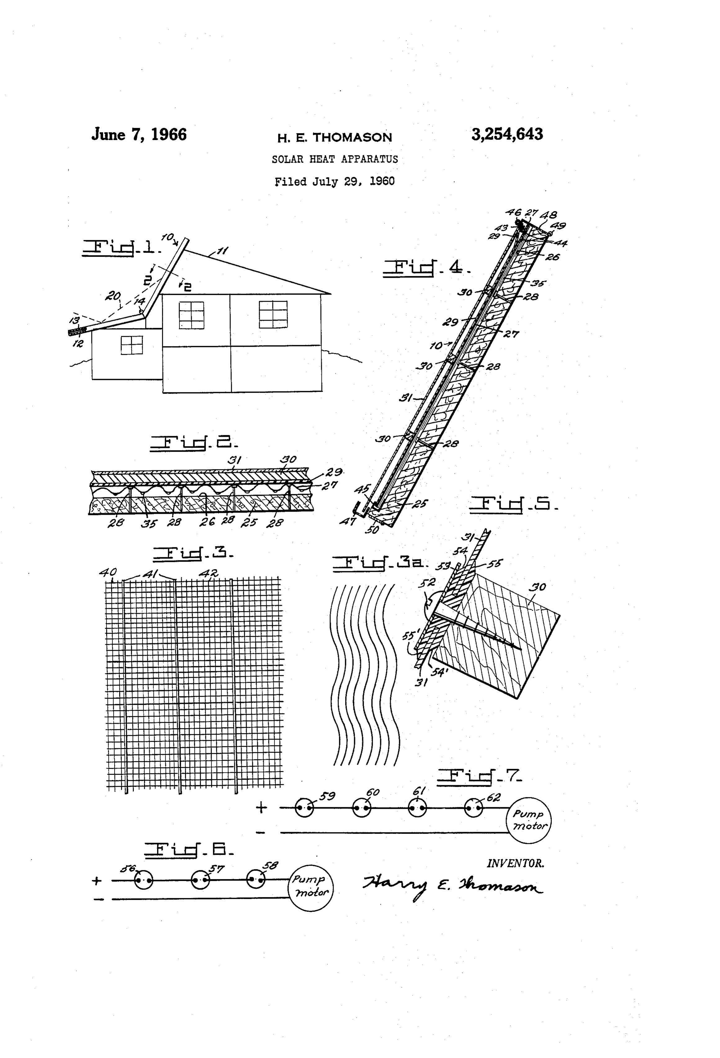
3,254,643 tions, as will be explained later. During the hot months SOLAR HEAT APPARATUS cover 13 protects against hail damage, and also reflects Harry E. Thomason, 7354 Walker Mill Road SE., unwanted heat away from the collector by the reflective Washington, D.C. Surface on the side of the reflector opposite that used Filed July 29, 1960, Ser. No. 46,213 during the colder months to help prolong the life of col 8 Claims. (C. 126-271) lector material and to help keep the home cooler. Generally it is desirable to have some heat collection,
The present invention relates to solar heat collectors even during the summer, for domestic water heating and for converting incoming solar rays into heat and for such. Thus, if desired, the cover 13 may be designed trapping such heat for various purposes and uses. Al 10 not to cover the entire collector and to thereby leave though not limited to such uses, the present invention is part of it exposed for supplying the smaller heat load. usable to heat gases or liquids, which in turn can be used Further, although the deflective cover 13 is shown as for space heating, domestic water heating, heating of covering a garage or part of the home, obviously such Swimming pools, heating of greenhouses, and for many reflective unit may itself be merely a wintertime carport other purposes. 5 roof or may be added above a carport roof or other. Al Referring more particularly to the drawing: though illustrated as hinged to the structure at 14, it is FIG. 1 is an end elevation of a building showing an obvious that the protective reflector may be attached example of a construction embodying the present inven otherwise, or may be detachably secured to be stored tion. away when not needed. Means to hold the cover 13 in FIG. 2 is a view along line 2-2 of FIG. 1 illustrating 20 its raised or lowered position may be provided if desired. one form of heat collector. As to the heat collector construction illustrated in FIG. 3 is a plan view of a portion of another form of FIG. 2, such collector comprises insulation 25 and a mate the heat collector. rial such as heat conductive corrugated sheet metal 27. FIG. 3a is a plan view of another modification. Preferably a vapor or liquid barrier is employed at 26, FIG. 4 is a detailed side view of the collector of FIG. 1 25 and Supports 28 maintain the sheet 27 spaced above bar showing other details of the invention. rier 26. One or more transparencies are employed, for FIG. 5 is a view through a spacer member illustrat example, a plastic transparency at 29 and a glass-like ing a preferred construction for securing the upper trans transparency 31 spaced thereabove by spacers 30. parency thereto. - In the modification of FIG. 2 a fluid is circulated be-, FIG. 6 is a diagram of a circuit for operating the pump 30 low the corrugated sheet 27. If the fluid is air, it is pref motor to circulate a fluid through the collector. erably introduced at the bottom and brought out at the FIG. 7 is a diagram of a circuit for operating the pump top. If the fluid to be heated is a liquid such as water, motor to circulate liquid over the heat dissipator for it is introduced near the top of the collector. In FIG. 4, Summertime use. one method for getting the liquid onto the undersides of As an example of how and where the present invention 35 the valleys is illustrated. A distributor manifold 43 is may be used, it has been illustrated in FIG. 1 in con used to introduce a small stream of liquid into each junction with a building such as a split level home, or a valley. Just below the manifold a hole is placed in each home with a garage attached thereto. The solar heat valley as at 44 so that the liquid may run through the trap is illustrated at 10 with a roof section 11. 40 hole to the underside of the valley and will cling to the The section of roof at 12 has a reflective cover section lower side of the valley as at 35 and will run down the at 13 which is pivoted at 14. During the colder months incline. The small streams of hot water are collected the reflective cover is in its lowermost position as illus in collector manifold 45 and are returned to a place of trated. Sunshine falling on this area is reflected toward storage or use. - the heat collector by the upper surface of reflector 13 as 45 It is obvious that other apparatus may be used to get illustrated at 20. Thus, the intensity of available solar the liquid onto the undersides of the valleys such as by energy on collector 10 is greatly increased by use of rel spraying the liquid thereagainst, by using an individual atively inexpensive cover 13, and more energy is available tube to project a small stream onto each valley or by per unit of area of heat collector. other expedients. - In some sections of the world severe hailstorms are a Instead of using corrugated heat collecting metal as in menace to a transparency such as glass which may be used FIG. 2, it has been found that a mesh-like material on the heat collector. Also, the summertime heat build as illustrated in FIG. 3 yields good results. Such mesh up in a heat collector is damaging to the materials and may, for example, be screen wire, plastic or other mate shortens the life of the materials. In addition, even though rial, preferably treated to make it black. A small stream the collector insulation is good, it is not perfect and some 55 of liquid to be heated is introduced at spaced intervals of the heat gets through into the attic or other portions adjacent the upper edge of the mesh. Although ordi of the home. Reflective cover 13 is adapted to be posi nary screen wire is reasonably satisfactory, it has been tioned over collector 10 when desired, such as by swing found that the liquid sometimes ends to skew sidewise as ing it about pivot 14. Said cover may be used during it travels down the mesh. The mesh 40 is preferably hot weather when hailstorms occur, or may be used dur 60 provided at 41, 42 with means to prevent such side skew ing hurricanes or during blizzard conditions in the event ing. This preventive means may take any one of many that sheer weight of snow and ice would tend to damage forms. As examples, enlarged strands may be used at the collector. However, the collector of the present 41 which will tend to prevent crossover of the liquid invention is readily cleared of snow under most condi while adding strength to the mesh if woven therein, or 3 s 4, which will provide support for the mesh if stretced there in relation to FIG. 3. If desired, the fluid itself may be eneath. Or, a material with a high degree of molecular black to enhance heat collection inasmuch as much of the attraction for the liquid may be used at 42 so that the Solar rays will be converted directly into heat within the liquid tends to “wet” areas 42 thoroughly but does not sheet of liquid itself. Efficiency of the heat collectors tend to cross over the area or strand 41. Atlernatively, 5 described is high whether solar energy comes in by direct a liquid repellent material may be at 41 so that the liquid, rays or by refected and diffused sky radiation. will not readily cross thereover. Or, two or more of FIG. 4 illustrates a heat collector having a second dis these expedients may be used jointly. tributor manifold at 46 and a second collector trough at Liquid flowing down the mesh acts as a good heat col 47. For wintertime use, water may be introduced onto lecting medium. However, a gas such as air may be O the top of transparency 31 to dislodge or wash snow or passed through the collector whereby heat transfer to ice from the collector in the event it does not skid off the gas is good due to the large surface contact between due to gravity. Also, trough 47 may be connected with the mesh and gas as it flows under and over and through the liquid reservoir if desired to provide makeup water the mesh. from rain as needed. During the sumertime, water is The mesh-like material may be physically separated circulated over the top of transparency 31 at night to from the insulation and a vapor-liquid barrier such as give up its heat to the atmosphere due to radiation, evap at 26 in F.G. 2 may be interposed between the insulation oration, and cooling by the cool night air, and the mesh. Certain advantages can be obtained by During the Summertime the daytime temperatures in placing the mesh in contact with the vapor-liquid barrier, side the collector rise to a high degree, especially if ap or in close proximity thereto, especially when the fluid to 20 paratus such as that at 13 in FIG. 1 is not used. To be heated is liquid. In such construction, the barrier pre permit such heat to escape more readily, damper 48 may vents the liquid from dripping from the mesh, even if be hinged at 49 to be opened and let the hot air out at the heat collector is set at a more-or-less horizontal incline. the top. A damper may be provided at 50 to let cool Examples of materials usable in such construction are: air in at the bottom. Thus, overheating may be mini screen wire mesh, which is dark itself or is treated to mized or avodied by natural air circulation. make it black to absorb solar heat, whereas the barrier In FIG. 5 a preferred means for fastening the outer therebeneath may be made of material such as plastic, transparency 31 to spacer 30 is illustrated. Such means sheet metal, or such. If the mesh is metallic or heat con comprises screws 52, washers 53 and generally H-shaped ducting, it will readily transfer the heat to the liquid or gasket 54. Said gasket is not only H-shaped to secure gas flowing thereover or therethrough. If the mesh is 30 two transparencies 31 therein, but also preferably has an not highly conductive of heat, a good rate of heat trans upwardly projecting lip 55 to assure that no rain can get fer the fluid will still be achieved due to the tremendous up around projection 55 even if it could get down be areas of contact between the fluid and the solar heated tween transparency 31 and gasket 54. The lower edge (mesh. If the barrier itself is dark and heat absorbing it of the gasket is preferably formed somewat reversely of will tend to be heated when some of the sun rays get the upper edge with a downwardly projecting lip 55' lower through the mesh and will tend to intensify the heat in than lip 54'. Thus, the same type of gasket may be used the collector, and will also tend to heat any gas or liquid between the vertical joints of the transparencies and such coming in contact therewith. On the other hand, if the may project upwardly to meet shortened lip 54 whereby barrier is reflective it will tend to "bounce' heat rays back 40 rainwater will be diverted over the joint by overhanging against the mesh from beneath when the Sun is substan lip 55.
tially at right angles to the collector at which time Some FiG. 6 illustrates a circuit for operating the pump of the rays get through the mesh. Thus the mesh is motor for the solar heat collector and thereby controlling bombarded from above by direct solar rays and is bom flow of fluid through the collector whether it be liquid barded from beneath by reflected or secondary rays. Of or gas. Such circuit includes a photoelectric cell or course when the sun is many degrees past, or ahead of, "electric eye' 56 to determine whether the weather is a position at right angles to the collector then the strands Sunny or cloudy, a time switch 57 which will cut on of the mesh will intercept substantially all sun rays di daily from say 8:30 to 4:00 and a temperature switch rectly. Also, as the seasons change and the Sun is higher 58, which is preferably located where the heat is stored or lower in the sky the mesh will intercept most of the and which will cut off when the storage temperature rays directly when the rays do not strike the collector reaches a desired level. These switches are in series. at right angles thereto. Thus, if the Sun comes up on a cold morning, bright The transparent material above the heat collector mesh enough to actuate the electric eye, but is not yet intense may be in contact or substantially in contact with the enough to yield useful heating, the electric eye switch mesh, or may be spaced thereabove if desired. It is turns on but the time switch keeps the circulating pump apparent that the mesh material may be sandwiched be cut off until say 8:30 when solar energy received is in tween the transparency 29 and the barrier 26 and that, tense enough to be useful. At this pre-selected time the if the spacing is not great, the mesh will tend to spread time Switch will cut on and if the level of heat in the the small streams of liquid entering the collector into a Storage apparatus is low and needs to be increased, the sheet of liquid of thin dimensions so as to have a maxi temperature switch will be closed and the pump will mum of exposure of the liquid to solar rays plus a 60 operate to circulate fluid through the collector to collect maximum of exposure of the liquid to the heat collecting Solar heat. Then, suppose it becomes cloudy, the elec mesh. As FIG. 3a illustrates the blackened heat absorb tric eye cuts the pump off and the gas or liquid heat ing strands may take forms other than mesh-like illustrated transfer medium is no longer circulated through the col in FIG. 3. If the strands are zig-zagged for example lector. Suppose the sun comes back out, and stays out, there will be a retardation of fluid flow through the col 65 the electric eye Switch cuts back on and the pump operates lector, whether liquid or gas, plus more positive contact until the time Switch cuts off at say 4:00, or until the between the fluid and strands as the fluid flows a tortious storage temperature level is as high as desired, at which path through the collector. In this modification the time the temperature responsive switch cuts off. In any strands are preferably either in contact with the trans event, as soon as the collector pump is cut off the liquid parency thereabove and the barrier therebeneath, or are in the System, if liquid is used, drains from the collector in close proximity thereto. As a practical manner of imediately and cannot freeze up and burst the collector. manufacture the strands may be secured to either the During some days clouds and sunshine come inter transparency, or to the barrier, or to both. Of course mittently and will start and stop the pump unnecessarily liquid repellent strands, or spaced enlarged strands, or frequently. In such instance, a time delay device may liquid attracting strands may be used if desired, as taught be used to prevent immediate cut on or cut off when the 4 o 6 "electric eye' 56 is actuated. While it is possible to sub edge of said mesh to collect the small streams of heated stitute a reverse acting thermostatic switch for the electric liquid for return to a point of storage or use, said mesh eye, to turn the pump motor on when solar heat is avail having spaced enlarged strands to minimize side skewing able and to turn it off when no heat is available, the elec of the liquid as it flows down saidmesh. tric eye has certain advantages. 5 4. A Solar heat collector comprising an insulating base, FIG. 7 illustrates a circuit and switches preferred for a mesh-like heat collecting sheet spaced thereabove, at operating the summertime cooling apparatus to supply least one transparency above said heat collecting sheet, liquid to distributor manifold 46. Such circuit includes said collector being mountable in an inclined position to a "humidostat” switch 59, a time switch 60 and a tem provide an upper edge and a lower edge, a distributor perature responsive switch 61. Time switch 60 will turn 10 manifold to introduce small streams of cool liquid at on nightly during the hot summer from say 10:00 p.m. spaced intervals along the upper edge of said mesh-like to 6.00 a.m. If the night is fairly dry then "humidostat” collecting sheet such that the liquid will flow down the 59 will be closed and the liquid will be circulated through inclined mesh, and a collector manifold at the lower edge manifold 46, over transparency 31, to collector trough of said mesh to collect the small streams of heated liquid 47 and back to the "cold' storage apparatus. Cooling 5 for return to a point of storage or use, said mesh having takes place due to evaporation and radiation as the fluid spaced strands having surfaces of a low degree of molecu flows over transparency 31. However, if the humidity lar attraction for said liquid to repel said liquid and to is extremely high so that evaporative cooling is only thereby aid in channeling the liquid. nominal, the "humidostat' 59 will prevent the apparatus 5. A solar heat collector comprising an insulating base, from operating. Temperature responsive switch 61 may 20 a heat collecting sheet thereabove and at least one trans be used to sense outside temperatures so that the dis parency above said sheet, said collector being mountable sipator will not come on early during an extremely hot in an inclined position to provide an upper edge and a night when heat dissipation may be low. However, if lower edge, said collector including means to introduce desired, both the "humidostat' 59 and the outdoor tem fluid in heat exchange relationship with said heat collect perature sensing switch 61 may be omitted so that the 25 ing sheet, said collector including outlet means for said heat dissipator will operate every summer night from say fluid, and a protective reflective cover having reflective 10:00 p.m. to 6:00 a.m. if the “cold' storage apparatus Surfaces on both sides thereof to be placed over said col needs chilling. If desired, a temperature responsive lector to minimize collector damage by hail, sleet and switch 62 may be provided to sense the “cold' storage the like and to reflect solar energy away from the col apparatus temperature. If this temperature is low enough, 30 lector by one of the reflective surfaces to minimize dam switch 62 will cut out so that the pump will not operate age by unnecessary heat buildup, the opposite reflective again until further cooling is needed. surface of said covering being positionable to intensify Although specific forms of the invention are disclosed solar heat input to said collector when desired, said cover to illustrate the underlying principles, yet modifications 35 ing being hinged adjacent the lower edge of said heat may be made which fall within the spirit of the invention. collector, forming a reflector-protector when swung up What I claim is: over the collector and adapted to form a roof section for 1. A solar heat collector comprising an insulating base, a garage or the like when swung out to intensify solar. a mesh-like heat collecting sheet spaced thereabove, at heat input to the collector.
least one transparency above said heat collecting sheet, 40 6. A heat collector-heat dissipator comprising a solar said collector being mountable in an inclined position to heat collector having a heat dissipator thereabove, means provide an upper edge and a lower edge, a distributor to bring liquid to be cooled onto the top of said collector manifold to introduce small streams of cool liquid at for nighttime cooling, a circuit to control said means spaced intervals along the upper edge of said mesh-like comprising, in series, an electrical time switch the con collecting sheet such that the liquid will flow down the tacts of which are closed and opened at predetermined inclined mesh, and a collector manifold at the lower times, a humidity controlled switch to stop said means edge of said mesh to collect the small streams of heated when relative humidity of the ambient air rises to a pre liquid for return to a point of storage or use, said mesh determined level, a thermostatic switch subjected to ambi having means to minimize side skewing of the liquid as ent air temperatures and whose contacts close when the it travels down said mesh. ambient air temperature is below a pre-set level, and a 2. A solar heat collector comprising an insulating base, 50 reverse-acting thermostat subjected to the temperature of a mesh-like heat collecting sheet spaced thereabove, at stored liquid cooled by the heat dissipator and whose least one transparency above said heat collecting sheet, contacts close when the temperature rises above a pre-set said collector being mountable in an inclined position to level.
provide an upper edge and a lower edge, a distributor 7. A heat collector-heat dissipator comprising a solar manifold to introduce small streams of cool liquid at 55 heat collector having a heat dissipator thereabove, means spaced intervals along the upper edge of said mesh-like to bring liquid to be cooled onto the top of said collector collecting sheet such that the liquid will flow down the for nighttime cooling, a circuit to control said means com inclined mesh, and a collector manifold at the lower prising, in series, an electrical time switch the contacts edge of said mesh to collect the small streams of heated of which are closed and opened at predetermined times, liquid for return to a point of storage or use, said mesh 60 and a humidity controlled switch to stop said means when having areas with surfaces of a high degree of molecular relative humidity of the ambient air rises to a predeter attraction for said liquid and areas with surfaces of a low mined level.
degree of molecular attraction to secure good wetting 8. A solar heat collector comprising an insulated base characteristics of said mesh and to help control the flow and a mesh-like material thereabove with a transparency pattern down said mesh. above said mesh-like material, means to channel fluid to 3. A solar heat collector comprising an insulating base, be heated flowing along said mesh-like material, means a mesh-like heat collecting sheet spaced thereabove, at to distribute fluid to be heated to said mesh-like material, least one transparency above said heat collecting sheet, means to collect fluid heated by said mesh-like material, means above the transparency to introduce liquid onto said collector being mountable in an inclined position to 70 said provide an upper edge and a lower edge, a distributor radiation transparency for ice and snow removal or for heat and evaporative cooling, collector means to col manifold to introduce Small streams of cool liquid at lect liquid flowing from said transparency, damper means spaced intervals along the upper edge of said mesh-like at the top and at the bottom of said collector to permit collecting sheet such that the liquid will flow down the ventilation and escape of excess heat when such dampers inclined mesh, and a collector manifold at the lower 75 are open, and a protective reflective cover to be placed 5 over said collector to prevent damage by hail and such 2,358,476 9/1944 Routh et al. -------- 126-271 or by unnecessary heat buildup or to be placed in a re- 2,396,338 3/1946 Newton -------------- 237-1 flective position to intensify heat on said collector when 2,529,621 11/1950 Mayo ---------------- 23.7-1 desired. 2,545,054 3/1951 Stitz ---------------- 236-46 References Cited by the Examiner 5 2,660,863 12/1953 Gerhart ---------- 126-271 X
UNITED STATES PATENTS 2,975,446 2/1961 White -------------- 236-46 201,439 3/1878 Moreau ------------ 126-270 2,998,005 8/1961 Johnston ----------- 126-270 842,658 1/1907 Haskell ------------ 126-271 3,025,851 3/1962 Steinberg ----------- 126-270
1,093,925 4/1914 Foresman ---------- 126-271 FOREIGN PATENTS 1,130,870 3/1915 Willsie ----------- 126-27 X 909,092 11/1945 France. 1,240,890 9/1917 Shuman et al. ------- 126-271 1,062,948 12/1953 France. 1,808,058 6/1931. Morrison --------- 20-564 X 23,624 of 1911 Great Britain. 1989,999 2/1935 Niederle ----------- 126-271 5 547,467 8/1942 Great Britain. 2,104,088 1/1938 Lyman ------------ 257 274 817,995 8/1959 Great Britain.
JAMES W. WESTHAVER, Primary Examiner. m 2,238,924 4/1941 Bennett ------------ 257-180 20 PERCY L. PATRICK, CHARLESSUKALO, Examiners. 2,342,211 2/1944 Newton ---------- 126-271 X C. J. MYHRE, E. M. OLSTEIN, Assistant Examiners.
Provenance
- Collection
- Patents citing this work
- Pages
- 5
- Method
- pdftotext (the PDF's own text layer) + pdftoppm 300dpi page scans
- Patent office record
- patents.google.com →
- Source
- Google Patents citing-documents table
- Assignee
- Harry E Thomason
- Published
- 1966-06-07
- Transcribed from
- patentimages.storage.googleapis.com →