

patent · US4166769A
Solar heat apparatus
4 September 1979
Text
Page 1bibliographic recordscan →
United States Patent (19)
Dukess
(54). SOLAR HEAT APPARATUS
76 Inventor: Joseph Dukess, 931 Greacen Point
Rd., Mamaroneck, N.Y. 10543
Int. Cl? ............................ CO2B1/04; F24J 3/02 52 U.S. C. ............................. 202/234; 203/DIG. 1;
Field of Search ............................... 126/270, 271;
3,174,915 3/1965 Edlin ... ... 202/234 3,351,536 v1967 Fox ..... . 202/234 3,397,117 8/1968 Smith et al. . 202/234 4,043,35 8/1977 Cooper ................................. 126/271
EXPANDABLE HEAT
EXCHANGER
4,056,093 1/1977 Burger ................................. 126/271 4,057,048 11/1977 Maine ................................... 126/271 Primary Examiner-Wilbur L. Bascomb, Jr.
Attorney, Agent, or Firm-Kenneth S. Goldfarb
A solar energy device comprising a body having a plu rality of spaced focusing lenses to concentrate direct and reflected rays from the sun. A heat receiving mem ber is inside of said body. One of the body and the member is expansible and contractible so as to direct the member into exact convergence with the focal points of said lenses. The member is supported within said body and fed fluid to be heated. The heated fluid is then removed from the member. The heat receiving member that is expansible and contractible may be employed separately and used as a prime mover.
4. Claims, 5 Drawing Figures
Drawings
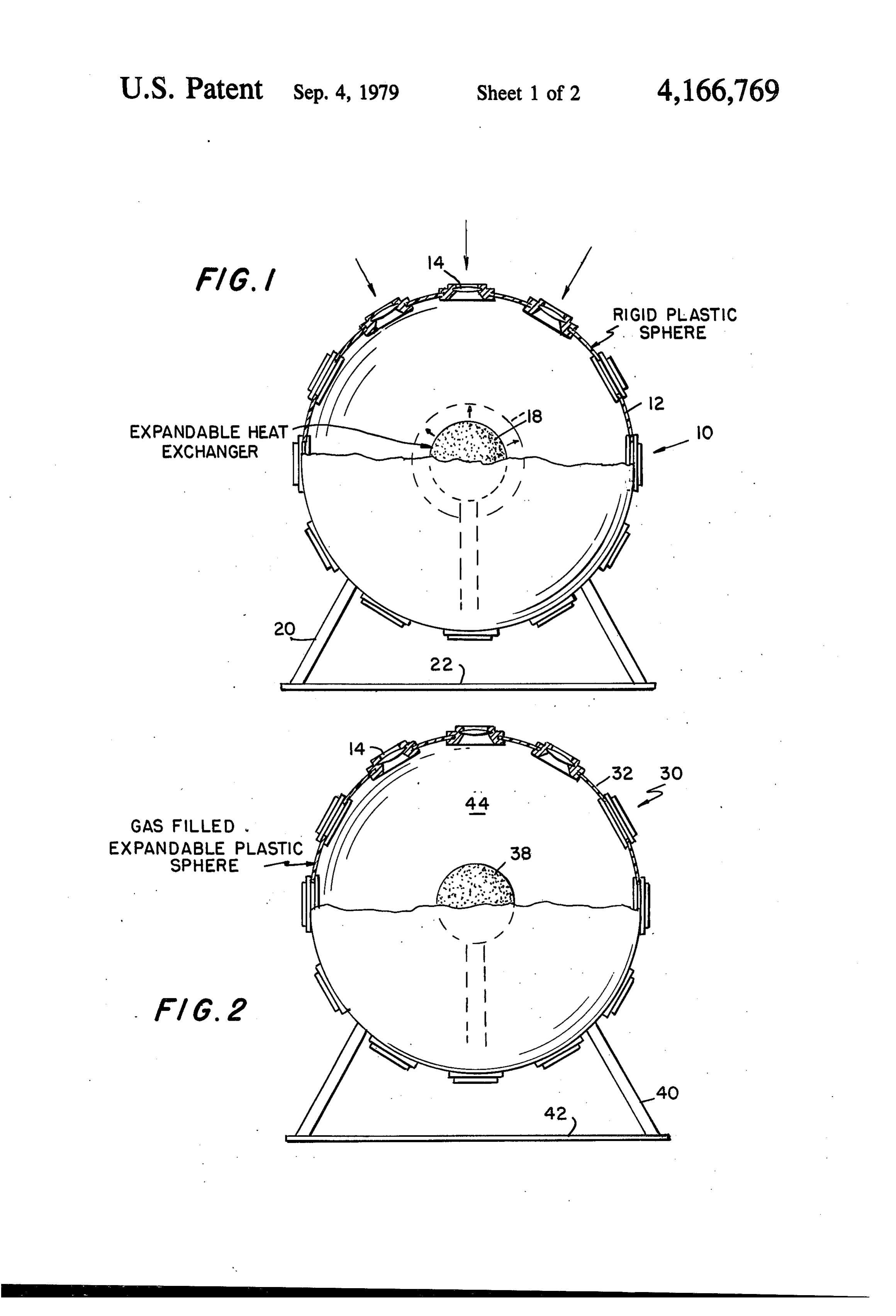
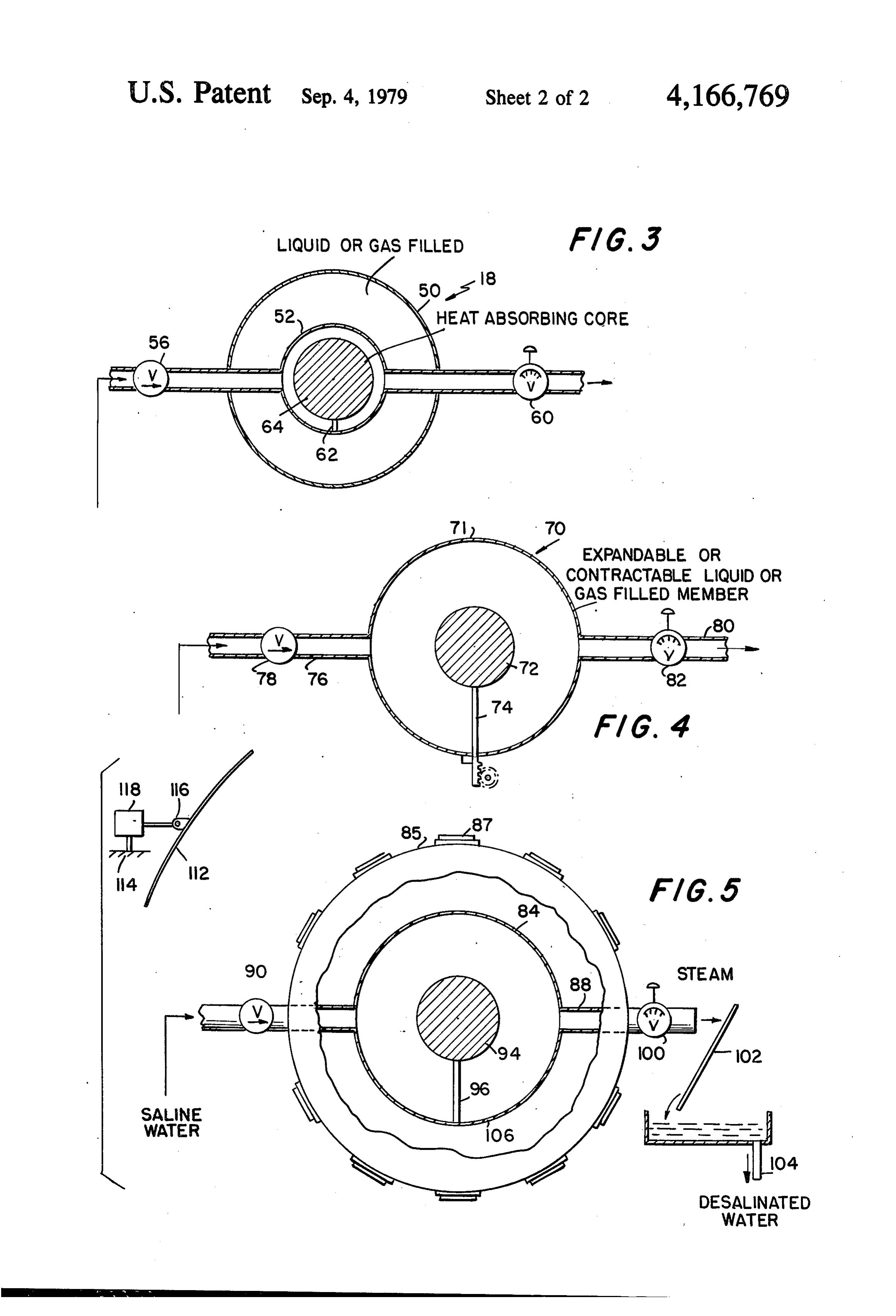
FIG. 2 is view similar to FIG. 1, illustrating another
Page 2drawing sheetscan →
Page 3drawing sheetscan →
Page 4scan →
FIG. 2 is view similar to FIG. 1, illustrating another
SOLAR HEAT APPARATUS embodiment of the invention wherein the body is flexi ble and the member is rigid;
BACKGROUND OF THE INVENTION FIG. 3 is a sectional schematic view illustrating de
1. field of the invention
5 tails of the invention;
The present invention relates to a solar energy de theFIG. 4 is a sectional detail veiw showing in particular structure of the heating member; and vice, and more particularly to an apparatus for collect FIG. 5 is a schematic illustration of a desalinization ing the radiant energy of the sun through direct and plant in accordance with the concepts of the invention.
2. DESCRIPTION OF THE PRIOR ART DETAILED DESCRIPTION OF THE In the past various arrangements of lenses have been INVENTION used to concentrate the rays of the sun for the purpose With continuing reference to the accompanying of extracting solar energy. drawings wherein like reference numerals designate In U.S. Pat. No. 3,934,573 there is disclosed the use of 5 similiar parts throughout the various views, reference a spherical system for directing suns rays through lenses numeral 10 designates an embodiment of the solar heat onto a boiler. However, the heat from such rigidly ing device as shown in FIG. 1. In this embodiment a concentrated lenses requires the use of expensive mate rigid sphere 12 of plastic or metal is provided with a rials for use in the boiler and eliminates the possiblity of plurality of lenses 14 for focusing both direct and re using low cost materials in the production of solar en 20 flected rays from the sun. The sphere 12 may be trans ergy. No means are provided for moving the boiler skin parent. The lenses 14 are disposed about the entire sur slightly out of focus upon application of much heat in face of the sphere 12. The lenses and/or the entire inner U.S. Pat. No. 3,934,573. surface of the sphere 12 may be coated with a reflecting The expansion of fluids through application of solar 25 film. Within the sphere 12 there is an expansible and radiation is old in the art as shown in U.S. Pat. No. contractible body 18, the details of the construction 3,436,908 but such patent does not conceive of an ex being 12 is shown in FIGS. 3 through 5. The spherical body supported by stanchions or suitable supports 20 pansible and contractible member for heating fluids. above a mirror reflecting surface 22. Likewise, U.S. Pat. No. 3,908,631 which is directed to FIG. 2, there is shown a form 30 of invention wherein apparatus for converting solar radiation to thermal en 30 the spherical body 32 is made of a flexible clear resilient ergy by heating a gaseous stream of air does not utilize material having lenses 34 mounted an expansible and contractible member for minimizing and having a fluid heating memberall38about its surface therein which cost and production difficulties for the solar energy may be rigid or similar to the member 18. The sphere is apparatus. This patent shows the use of an inflatable mounted on standards 40 above a reflecting surface 42. member, 35 The spherical body may be filed with fluid, or an inert
The heating member may be in the form shown in
It is the object of this invention to provide a low cost FIG. 3. Herein the member 18 includes an expansible solar energy device capable of being manufactured out and contractible sphere 50 having therein a boiler 52 of inexpensive materials, which can be used for individ 40 connected to intake conduct 54 provided with a one ual installations for homes, factories, offices to provide way valve 56 and a discharge conduit 58 provided with heat and energy, yet which may be made of materials of a pressure gage 60. The space between the member lower melting temperatures thereby facilitating manu sphere 50 and the boiler 52 is filled with a fluid, prefera facturing processes. bly a gas. Inside the boiler 52 there is supported at 62 a The concept of the invention is to provide a solar 45 black heat absorbing body 64.
energy device in the form of a body having a plurality In operation the rays of the sun are directed through of spaced focusing lenses thereon for concentrating lenses 14 onto the surface of the sphere 50. When the direct and reflected rays of the sun. A member is dis sphere 50 has been heated to the point of convergence posed in the body and contains a black heat absorbent 50 with the focal point of lenses 14 it will expand beyond core. Either the body or the member is expansible and the focal point unless additional cold fluid is introduced contractible so as to direct the lenses into focus on the into the boiler 52 or some fluid is allowed to escape. surface of the member until a predetermined tempera focal allows
This for expansion and contraction out of the ture is reached whereby the member will expand so its boilerpoint of the lenses to prevent spot burnout of the surface is out of the focal point to lessen concentrated 55 makingand permit cheaper materials to be used while sure of the most available heat.
heat thereon. Thereafter contraction will return the focal point to the surface of the member and heating ingInmember FIG. 4 there is shown a modified form of the heat 70 which may be used separately. The continues at optimum rate. The member is suspended on heating member the feed conduit and discharge conduit for delivering inlet conduit 76 70 is an expansible shell 71 having an fluid to be heated and for receiving heated fluid. The with a one way inlet valve. thereto connected
Discharge which is provided conduit 80 pro solar energy device is made of easily worked materials vided with a valved pressure gage to serve as a pressure including plastics and metals and is adapted for home regulator is connected to the shell 71. A black body 72 use for heating, power, and desalinization. supported at 74 is provided within the shell 7 to absorb BRIEF DESCRIPTION OF THE DRAWINGS heat and distribute heat to incoming fluid. Fixed to the 65 expansible shell 71 is a mounting plate carrying a
FIG. 1 is a schematic view of an embodiment of the toothed rod 75 which engages a gear 77 for driving a invention employing a rigid body and a flexible mem shaft 79. The gear 77 may have one direction of rota ber; tion. In this form of the invention the member 70 can be 5 placed in body or may derive its heat from a mirror, While the solar energy device has been described in parabolic reflector or receiver or the like and may be several embodiments herein, it is recognized that varia used to transport, for example, a parabolic mirror. The tions and changes may be made within the scope of the shaft 79 when rotated can carry the reflector along a appended claims.
solar track. As a cloud cover develops when the shell 71 5 We claim:
is contracting a ratchet arrangement could disengage 1. A solar energy device comprising body means, an the movement of the reflector. As solar heat redevelops expansible and contractable member means inside said the drive of the shaft 79 would keep the reflector mov body means, lens means including a plurality of spaced ing. Thus the arrangement could track mirrors and focusing lenses on said body means for concentrating other heat seeking devices. After a predetermined 10 direct and reflected rays from the sun onto said member length of time the various devices could be sent back, means to heat said member means to expand and con by spring device or the like, for the start of another tract said member means to direct said member means solar day. into exact convergence with the focal points of said As shown in FIG. 5, this solar energy device may be lenses in accordance with heat from sun rays focused on employed for desalinization of water. In this embodi 15 said member means, heat absorbing core means in said ment the body 85 is provided with lenses 87. The body member means, means for introducing fluid to be heated 85 may be transparent and the body and the lenses may into said member means and means for removing heated be provided with all inner "one way” coating. The fluid from said member means.
heating member 84 is mounted within the body 80 by 2. A solar energy device comprising body means inlet conduit 86 connected to a source of saline water 20 having len means including a plurality of spaced focus and by discharge conduit 88. Saline water entering ing lenses for concentrating direct and reflected rays through one way valve 90 will pass into the heating from the sun, heat-receiving member means inside said member 84 where the saline water will be in contact body means, fluid means in said body means for expand with black body 94 supported at 96 within the heating ing and contracting said body means said lens, means member 84. Heat from the focussed suns rays on the 25 directing sun's rays onto said member means for heating member 84 will turn the saline water to steam and salt. said member means and said fluid means and for posi The steam will be at a pressure regulated by pressure tioning said lenses with focal points of said lenses in gage and valve 100 and will flow into a condenser, alignment with said member means, means for introduc shown schematically by condenser plate 102 and thence ing said other fluid to be heated into said member at 104 to a reservoir for further consumption. The salt 30 means, and means for removing fluid from said member can be removed by flushing with salt water pericodi means. . . . . ? cally or through use of an access port 106. - 3. A solar energy device according to claim 2, In order to enhance heating capabilities a reflector, wherein said means for introducing said other fluid into such as a parabolic reflector, may be employed and said member means and said means for removing said mounted for more than one degree of movement about 35 other fluid from said member means support said mem a track on a universal joint controllable by a direct ber means within said body means. mechanical linkage as heretofore described with refer 4. A solar enery device according to claim 1 includ ence to FIG. 4, or by a sun following photoelectric ing a reflecting surface and means for supporting said device 118. Thus the reflector can move to assume an body means above saidk reflecting surface.
optimum position by following the sun.
Provenance
- Collection
- Patents citing this work
- Pages
- 5
- Method
- pdftotext (the PDF's own text layer) + pdftoppm 300dpi page scans
- Patent office record
- patents.google.com →
- Source
- Google Patents citing-documents table
- Assignee
- Joseph Dukess
- Published
- 1979-09-04
- Transcribed from
- patentimages.storage.googleapis.com →