

patent · US4334522A
Solar heat apparatus
15 June 1982
Text
Page 1bibliographic recordscan →
United States Patent (19)
Dukess
54). SOLAR HEAT APPARATUS
(76) Inventor: Joseph Dukess, 931 Greacen Point
Rd., Mamaroneck, N.Y. 10543 * Notice: The portion of the term of this patent subsequent to Sep. 4, 1996, has been disclaimed.
Related U.S. Application Data 63 Continuation-in-part of Ser. No. 794,448, May 6, 1977,
51 Int. Cl'................................................. F24J 3/02 52 U.S. C. .............. a sm as ess as a s a sa as a so 126/440; 126/418
3,351,536 11/1967 Fox ...................................... 202/234
4,043,315 8/1977 Cooper ................................ 126/440 4,056,093 11/1977 Barger ... ... 126/440 4,057,048 11/1977 Maine ..... ... 126/441 4,166,769 9/1979 Dukess ................................ 126/440 Primary Examiner-Samuel Scott
Assistant Examiner-G. Anderson
Attorney, Agent, or Firm-Alan H. Levine
A solar energy device comprising a member adapted to contain a liquid and a lens for concentrating rays from the sun on a surface of the member. Cold liquid enters the member and heated liquid is extracted from it. A device produces relative movement between the lens and member surface in response to variations in temper ature of the liquid in the member so as to move the member surface into and out of coincidence with the focal point of the lens. The device producing movement may include an element which expands and contracts in response to temperature variations.
10 Claims, 8 Drawing Figures
Drawings
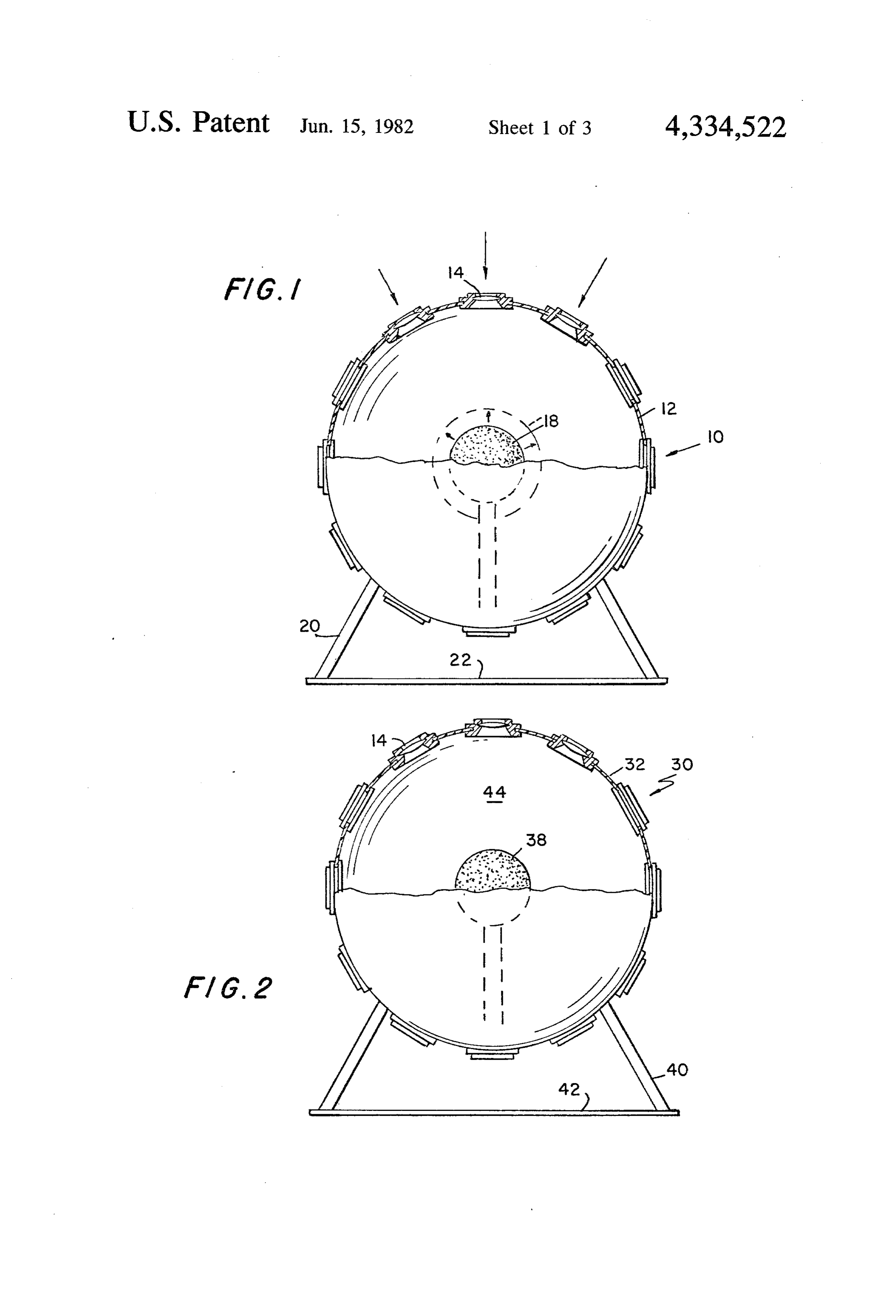
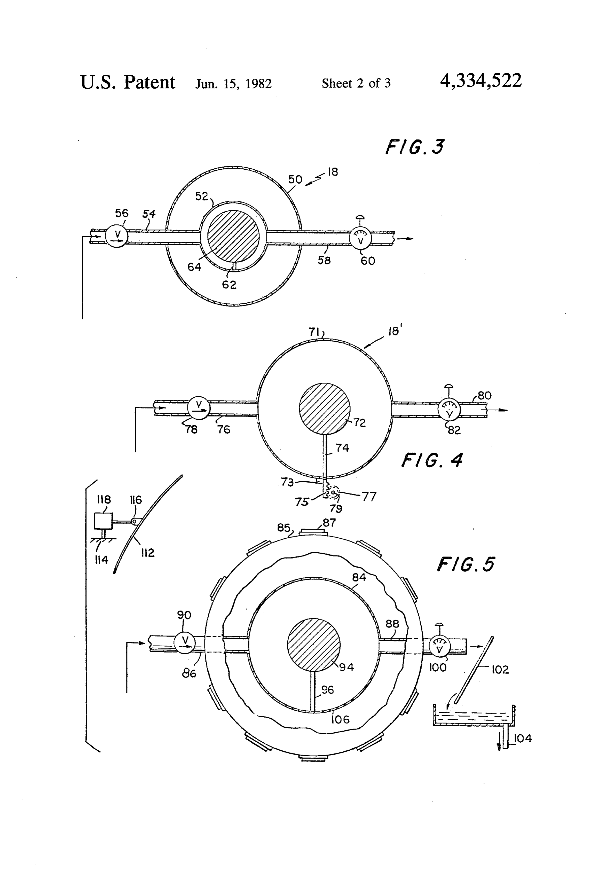
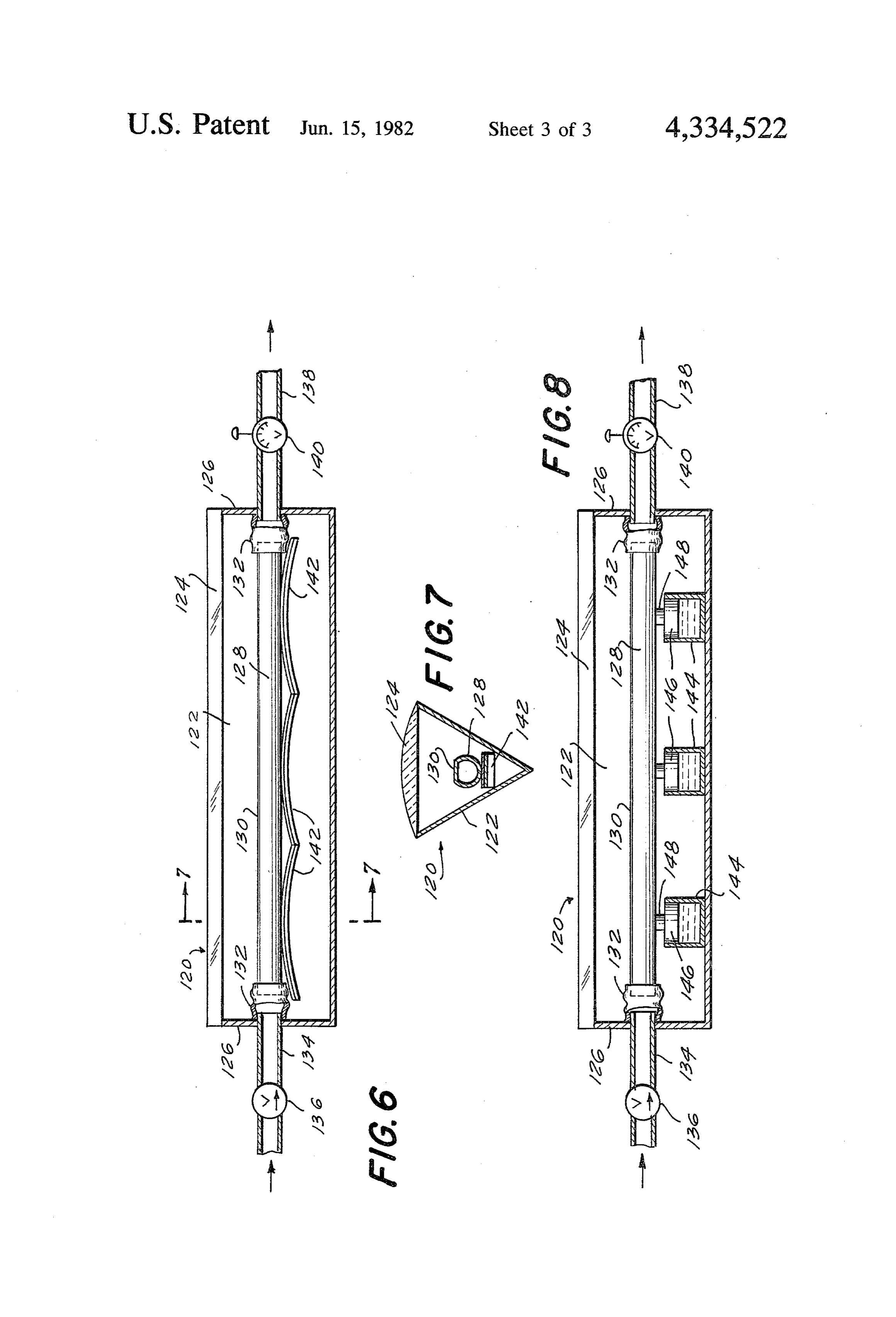
FIG. 1 is a schematic view of one embodiment of the
Page 2drawing sheetscan →
Page 3drawing sheetscan →
Page 4drawing sheetscan →
Page 5scan →
FIG. 1 is a schematic view of one embodiment of the
SOLAR HEAT APPARATUS invention employing a rigid outer body and a flexible inner member;
This application is a continuation-in-part of copend FIG. 2 is view similar to FIG. 1, illustrating another ing application Ser. No. 794,448, filed May 6, 1977, nowembodiment of the invention wherein the outer body is U.S. Pat. No. 4,166,769. flexible and the inner member is rigid; The present invention relates to a solar energy de FIG. 3 is a sectional schematic view illustrating in vice, and more particularly to an apparatus for collect greater detail the flexible inner member; ing the radiant energy of the sun through direct and 10 FIG. 4 is a sectional schematic view showing a modi reflected rays therefrom. fied form of the heating member;
In the past various arrangements of lenses have been FIG. 5 is a schematic illustration of a desalinization used to concentrate the rays of the sun for the purpose plant in accordance with the concepts of the invention; of extracting solar energy. FIG. 6 is a longitudinal cross-sectional view of a In U.S. Pat. No. 3,934,573 there is disciosed the use of 5 further embodiment of the invention, wherein a sepa a spherical system for directing the sun's rays through and rate device produces movement between the member lenses onto a boiler. However, the heat from such rig body;
FIG. 7 is transverse cross-sectional view taken on line idly mounted lenses focused on a rigid boiler requires 7-7 of FIG. 6; and the use of expensive materials for use in the boiler and FIG. 8 is a view similar to FIG. 6 of still another eliminates the possibility of using low cost materials in 20 embodiment of the invention. the production of solar energy. No means are provided With reference to the accompanying drawings, for moving the boiler skin slightly out of focus upon an wherein like reference numerals designate similar parts increase in temperature above a predetermined level.
The expansion of fluids through application of solar throughout ment of a the various views, FIG. 1 shows an embodi solar heating device 10 according to the pres radiation is old in the art as shown in U.S. Pat. No. 25 ent invention. In this embodiment, a rigid spherical 3,436,908 but such patent does not conceive a relatively body 12 of plastic or metal is provided with a plurality movable lens and container for heating fluids. Likewise, of lenses 14 for focusing both direct and reflected rays U.S. Pat. No. 3,908,631 which is directed to apparatus from the sun. The body 12 may be transparent. The for converting solar radiation to thermal energy by lenses 14 are disposed about the entire surface of body heating a gaseous stream of air does not utilize a rela 30 12. The lenses and/or the entire inner surface of body 12 tively movable lens and container for minimizing cost may be coated with a reflecting film. Within the spheri and production difficulties of the solar energy appara cal body 12 is an expansible and contractible member tlS. 18, the details of the construction of which are shown in It is the object of this invention to provide a low cost FIGS. 3 through 5. The spherical body 12 is supported Solar energy device capable of being manufactured out 35 by stanchions or suitable supports 20 above a mirror or of inexpensive materials, which can be used for individ other reflecting surface 22.
ual installations in homes, factories, and offices to pro The heating member 18 may be in the form shown in vide heat and energy, yet which may be made of materi FIG. 3. Herein the member 18 includes an expansible als of lower melting temperatures thereby facilitating and contractible sphere 50 having therein a rigid boiler manufacturing processes. 40 52 connected to intake conduit 54 provided with a one The concept of the invention is to provide a solar way valve 56 and a discharge conduit 58 with a pressure energy device in the form of a body having at least one gage 60. The space between the member sphere 50 and focusing lens thereon for concentrating direct and/or the boiler 52 is filled with a fluid, preferably a gas. In reflected rays of the sun on the surface of a liquid-con side the boiler 52 there is supported at 62 a black heat taining member disposed in the body and which may 45 absorbing body 64.
In operation, the rays of the sun are directed through contain a black heat absorbent core. Means are pro lenses 14 onto the surface of the sphere 50, which coin vided for relatively moving the member surface and cides with the focal points of lenses 14 or expands upon lens toward and away from each other in response to changes in temperature of the liquid in the member. For 50 heating to so coincide. As the sphere 50 continues to be example, either the body or the member is expansible additionalwill heated it expand beyond the lens focal points until cold fluid is introduced into the boiler 52 or and contractible so as to direct the lenses into focus on the surface of the member until a predetermined tem some fluid is allowed to escape at which point sphere 50 perature is reached whereby the member will expand so the surfaceThis contracts.
allows for expansion and contraction of sphere 50 out of the focal point of the its surface is out of the focal point to lessen concen 55 lenses to prevent spot burnout of the boiler and permit trated heat thereon. Thereafter contraction will return cheaper materials to be used while making use of the the focal point to the surface of the member and heating most available heat.
continues at the optimum rate. Alternatively, the body In FIG. 2 there is shown a form 30 of the invention and member may be rigid, and a device located within wherein the spherical body 32 is made of a flexible, the body which expands and contracts in response to 60 clear, resilient material having lenses 14 mounted all temperature variations and thereby produces relative about its surface and having a fluid heating member 38 movement between the lens and member. The solar therein which may be rigid or similar to the member 18. energy device is made of easily worked materials in The sphere is mounted on standards 40 above a reflect cluding plastics and metals and is adapted for home use ing surface 42. The spherical body may be filled with a for heating, power, and desalinization. 65 fluid, such as a suitable liquid or an inert gas 44. The alternating expansion and contraction of the As the interior of body 32 becomes heated, the focal member or body, or movement of the lens or member, points of lenses 14 move into coincidence with the sur can be harnessed to perform useful work. face of heating member 18. Further heating causes the 6 focal points to move radially outwardly beyond the In order to enhance heating capabilities a reflector, member 18. As heated water is extracted from member such as a parabolic reflector 112, may be employed and 18 and cold water introduced into it, the interior of mounted, for more than one degree of movement about body 32 cools bringing the lens focal points again into a track 114, on a universal joint 116 controllable by a coincidence with the surface of heating member 18. direct mechanical linkage as heretobefore described In FIG. 4 there is shown a modified form of the heat with reference to FIG. 4, or by a sun following photoe ing member, identified by the reference numeral 18, lectric device 118. Thus the reflector can move to as which may be used within body 12 or separately. The sume an optimum position by following the sun. heating member 70 includes an expansible spherical In the embodiment of the invention shown in FIGS. 10 6 and 7, outer body 120 includes an elongated rigid shell 71 having an inlet conduit 76 connected thereto which is provided with a one way inlet valve 78. Dis element 122, of a suitable metal or plastic, having a charge conduit 80, provided with a valved pressure V-shaped cross-section. Mounted on the upper edges of gage 82 to serve as a pressure regulator, is connected to element 122 is an elongated lens 124, such as a Fresnel the shell 71. A black body 72 supported at 74 is pro lens, preferably formed of transparent plastic. Body 120 vided within the shell 71 to absorb heat and distribute 15 is closed by two end walls 126. Within body 120 is a member 128, in the form of an heat to incoming fluid. Fixed to the expansible shell 71 elongated is a mounting plate 73 carrying a toothed rack 75 which tube, preferably having a flat surface 130 engages a gear 77 for driving a shaft 79. Although rack facing lens 124. The ends of member 128 are connected 75, and hence gear 77, move in two directions as shell 71 20 by flexible couplings 132, and through holes in end expands and contracts, a one-way clutch between gear walls 126, to an inlet conduit 134, provided with a one way valve 136, and to a discharge conduit 138 having a 77 and shaft 79 can be used to drive the shaft in one direction for performing useful work. In this form of the valved pressure gage 140.
invention the member 18" can be placed in body 12 or FIGS. Tubular member 128 is supported, in the example of may derive its heat from a mirror, parabolic reflector, 6 and 7, by a plurality of bimetallic strips 142 or receiver, or the like and may be used to transport, for 25 each having an arched configuration. Each strip is de signed so that it becomes more arched when heated, so example, a parabolic mirror. The shaft 79 when rotated as to move member 128 toward lens 124, and more can carry the reflector along a solar track. As a cloud flattened when cooled, so as to move member 128 away cover develops when the shell 71 is contracting a from lens 124.
ratchet arrangement could disengage the movement of 30 In use, rays of the sun are focused by lens 124 on to the reflector. As solar heat redevelops the drive of the surface 130 of member 128, which coincides with the shaft 79 would keep the reflector moving. Thus the arrangement could track mirrors and other heat seeking focal lic point of the lens or is moved upwardly by bimetal strips 142 to so coincide. As the water or other liquid devices. After a predetermined length of time the vari in member 128 is heated, the interior of body 120 be ous devices could be sent back, by spring device or the 35 comes heated, and strips 142 become more arched, like, for the start of another solar day. thereby moving member 128 closer to lens 124; hence The periodic movement of shaft 79 could be used to surface 130 moves upwardly out of the focus of the lens. lift a weight which thereafter can be allowed to fall to As heated water is removed from member 128, through perform some desired function. Alternatively, shell 71 conduit 138, and cold water introduced into it, through may be connected to a plunger within a fluid-filled 40 conduit 134, the temperature of the water in member chamber. Upon each expansion of shell 71, the plunger 128 decreases causing the temperature of the interior of pressurizes the chamber and pushes fluid out of the body 120 to decrease. As a result, bimetallic strips 142 chamber through a one-way valve. Upon each contrac become more flattened and member 128 moves down tion of shell 71, the plunger moves in the opposite direc wardly bringing surface 130 into coincidence with the tion and draws additional fluid, from a reservoir, into 45 focus of lens 124.
the chamber through a second one-way valve. The The embodiment of the invention shown in FIG. 8 is periodic pulses of fluid leaving the chamber can be used very similar to that of FIGS. 6 and 7, and therefore to perform some desired work. similar parts bear the same reference numerals in all As shown in FIG. 5, this solar energy device may be three figures. In FIG. 8, the means for providing rela employed for desalinization of water. In this embodi 50 tive movement between lens 124 and surface 130 are not ment, the outer body 85 is provided with lenses 87. The bimetallic strips. Instead, a plurality of cylindrical con body 85 may be transparent and the body and the lenses tainers 144 are provided, filled with a liquid, such as may be provided on their inner surfaces with a "one mercury, which expands with increased temperature way' coating. The resilient heating member 84 is and contracts as temperature decreases. A piston 146 mounted within the body 85 by inlet conduit 86 con 55 floates on the liquid surface in each container 144, the nected to a source of saline water and by discharge pistons supporting member 128 by means of piston rods conduit 88. Saline water entering through one way 148. As the temperature within member 128, and hence valve 90 will pass into the heating member 84 where the within body 120, rises, the liquid in containers 144 ex saline water will be in contact with black body 94 sup pand thereby lifting pistons 146 and hence member 128 ported at 96 within the heating member 84. Heat from 60 toward lens 124. When the temperature in body 120 the focused sun's rays on the member 84 will turn the decreases, the liquid in containers 144 contracts and saline water to steam and salt. The steam will be at a member 128 moves downwardly away from lens 124. In pressure regulated by pressure gage and valve 100 and this way, surface 130 is moved into and out of coinci will flow into a condenser, shown schematically by dence with the focus of lens 124. condenser plate 102 and thence at 104 to a reservoir for 65 In either of the embodiments of FIGS. 6-8, means further consumption. The salt can be removed by flush such as described above with respect to FIG. 4 can be ing with fresh water periodically or through use of an associated with the movement of member 128 to per access port 106. form useful work.
Page 7scan →
While the solar energy device has been described in member so as to move said surface of the member several embodiments herein, it is recognized that varia into and out of coincidence with the focal point of tions and changes may be made within the scope of the the lens.
appended claims. For example, although in FIGS. 1-5 2. A solar energy device as defined in claim 1 wherein body 12 and member 18 have been shown in spherical 5 said moving means includes an element which expands form, other shapes can be used. The body and member and contracts in response to temperature variations. could have relatively flat rectangular shapes similar to 3. A solar energy device as defined in claim 1 wherein that of a conventional solar water heater used on the said lens remains stationary and said moving means roof of a house, the lenses being arranged in a plane moves said member.
parallel to the flat surface of the heating member. Also, O 4. A solar energy device as defined in claim 1 wherein although in FIGS. 6-8 bimetallic strips 142 and piston said moving means includes a bimetallic strip. cylinder devices 144, 146 move member 128, they could 5. A solar energy device as defined in claim 1 wherein be mounted between element 122 and lens 124 so as to said moving means includes a container filled with a move the lens. liquid which expands and contracts in response to tem The invention has been shown and described in pre 15 perature variations.
ferred form only, and by way of example, and many 6. A solar energy device as defined in claim 1 includ variations may be made in the invention which will still ing a body within which said member is located, said be comprised within its spirit. It is understood, there moving means being located within said body between fore, that the invention is not limited to any specific said body and said member.
form or embodiment except insofar as such limitations 20 7. A solar energy device as defined in claim 6 wherein are included in the appended claims. said body carries said lens.
I claim: 8. A solar energy device as defined in claim 1 wherein 1. A solar energy device comprising: said moving means includes an expansible and contract a member adapted to contain a liquid, ible body within which said member is located, said at least one lens spaced from the member for concen 25 body carrying said lens.
trating rays from the sun on a surface of the mem 9. A solar energy device as defined in claim 1 wherein ber; at least a portion of said member is expansible and con means for introducing relatively cold liquid into the tractible, said portion serving as said moving means. member and withdrawing liquid at a higher tem 10. A solar energy device as defined in claim 1 includ perature from the member, and 30 ing means for transmitting the relative movement be means for relatively moving the member surface and tween said member and lens to a work-performing lens toward and away from each other in response mechanism.
to changes in temperature of the liquid within the 3k k k k k
Provenance
- Collection
- Patents citing this work
- Pages
- 7
- Method
- pdftotext (the PDF's own text layer) + pdftoppm 300dpi page scans
- Patent office record
- patents.google.com →
- Source
- Google Patents citing-documents table
- Assignee
- Joseph Dukess
- Published
- 1982-06-15
- Transcribed from
- patentimages.storage.googleapis.com →