

patent · US4043315A
Solar heat collector
23 August 1977
Text
Page 1scan →
United States Patent (19)
Cooper (54) soLAR HEAT COLLECTOR (76) Inventor: Nathan E. Cooper, Brookside Drive,
Woodbridge, Conn. 06525
51 Int. C.’................................................. F24J 3/02 52 U.S. C. ..................................... 126/270; 126/271
1,093,498 4/1914. Thring ............. see so to 126/271 1,658,455 2/1928 Metzech et al. ..................... 126/271 1,951,403 3/1934 Goddard .............................. 126/27 3,262,493 7/1966 Hervey ................................. 126/271.
3,466,119 9/1969 Francia ................................ 126/270 3,587,559 6/1971 - Nonaka ............................... 126/27 3,934,573 1/1976 Dandini................................ 126/270 Primary Examiner-Kenneth W.Sprague
An omni-directional solar heat collector having a trans parent, spherical outer shell, a spherical inner shell within the outer shell containing a plurality of light magnifying lenses spaced along the periphery thereof, and a plurality of heat collecting elements within said inner shell spaced from the magnifying lenses so that maximum light and heat intensity focuses upon said elements.
5 Claims, 7 Drawing Figures
Drawings
Page 2drawing sheetscan →
Page 3drawing sheetscan →
Page 4drawing sheetscan →
Page 5scan →
The solar heat collector of the present invention pro
SOLAR HEAT COLLECTOR vides a great many significant advantages. The device is inexpensive and extremely efficient. The spherical
BACKGROUND OF THE INVENTION shape is particularly desirable as it provides an omnidi The art has developed many devices to extract ther rectional device and enables exposure to light rays at mal energy from solar energy or light. These devices virtually any angle of the sun. The high efficiency of the are essentially collectors which are adapted to absorb device enables its use without the necessity of expensive the thermal component of the solar energy to heat an tracking mechanisms, although naturally these may be aqueous fluid. Without the use of some type of concen O provided if desired. The placement of light and heat trator, however, the temperature to which the aqueous intensification means around the periphery of the sphere fluid can be raised is generally quite low, so that effi provides an especially efficient unit which is capable of generating extremely high temperatures in the heat cient use of the collected energy is not possible.
Prior art devices may conventionally require the use transfer medium, e.g., 750 F. In addition, the device of of a tracking mechanism in order to track the movement 15 the present invention is versatile, esthetically pleasing of the sun with changes of the time of day and season. ings. readily adapted for installation on existing build and
These tracking mechanisms may be quite expensive, however, since they may require costly pivoting and BRIEF DESCRIPTION OF THE DRAWINGS rocking assemblies and also power for their operation, thereby further increasing overall cost. In addition, 20 structed 1inisaccordance
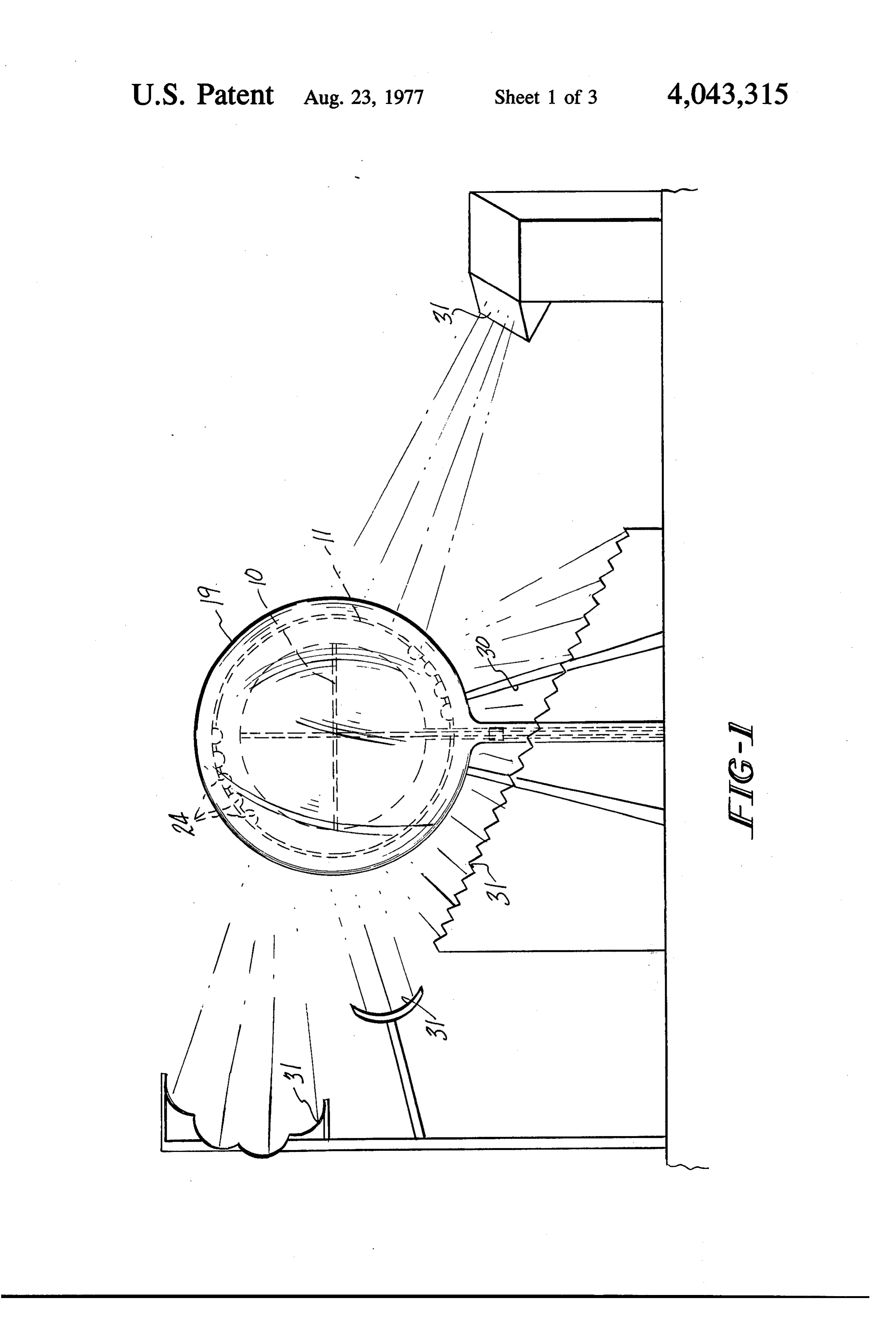
FIG. a side elevational view of a system con with the present invention;
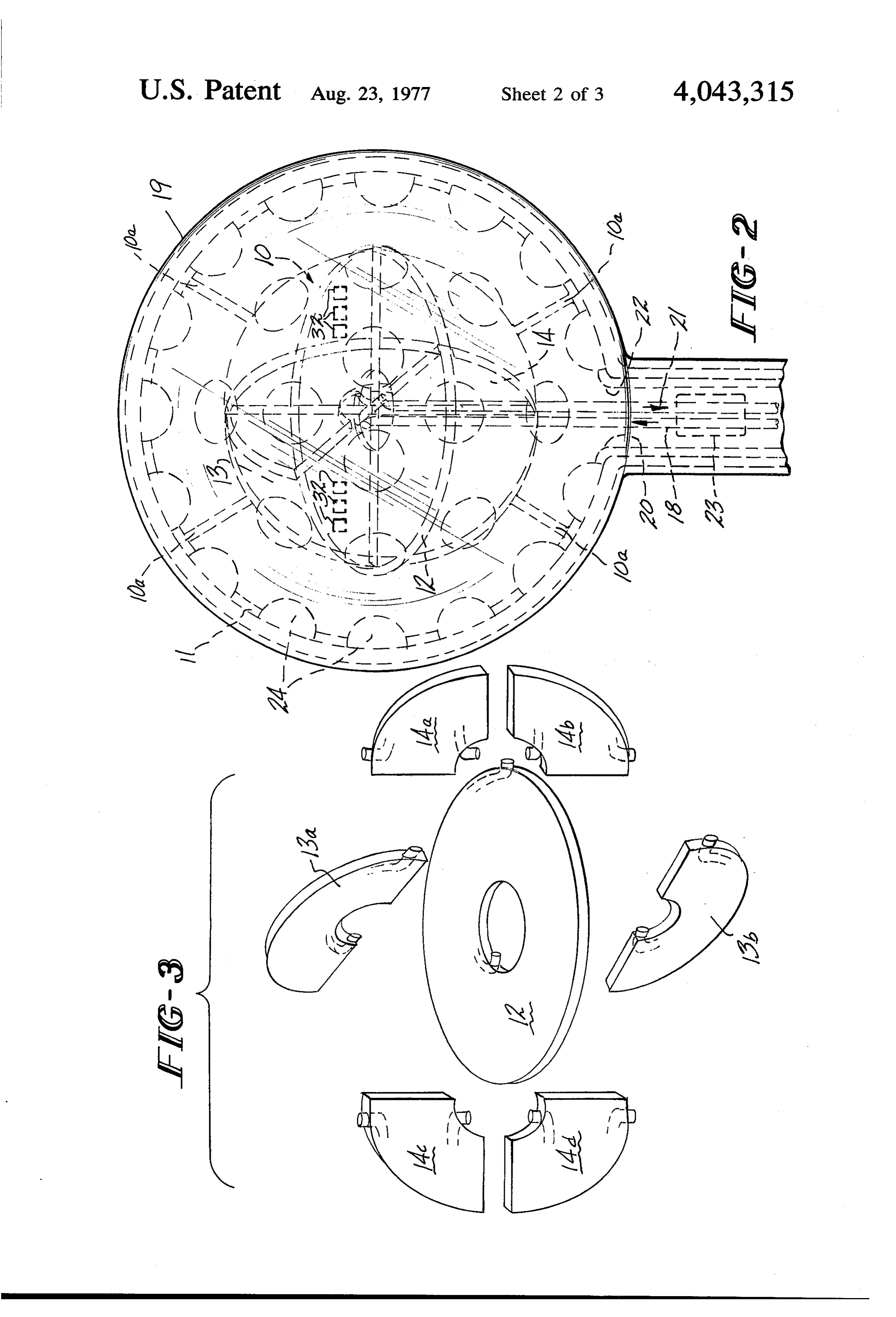
maintenance and repair costs are incurred particularly FIG. 2 is a partly schematic perspective view of the for moving parts. Still further, despite the foregoing, solar heat collector of the present invention showing these conventional devices may not achieve sufficient the inner shell, outer shell and heat collecting elements; efficiency to be commercially practicable, FIG. 3 is an exploded, perspective view showing the Accordingly, it is a principal object of the present 25 heat collecting elements of the present invention; invention to provide an inexpensive and efficient solar FIG. 4 is a sectional view of the solar heat collector of heat collector.
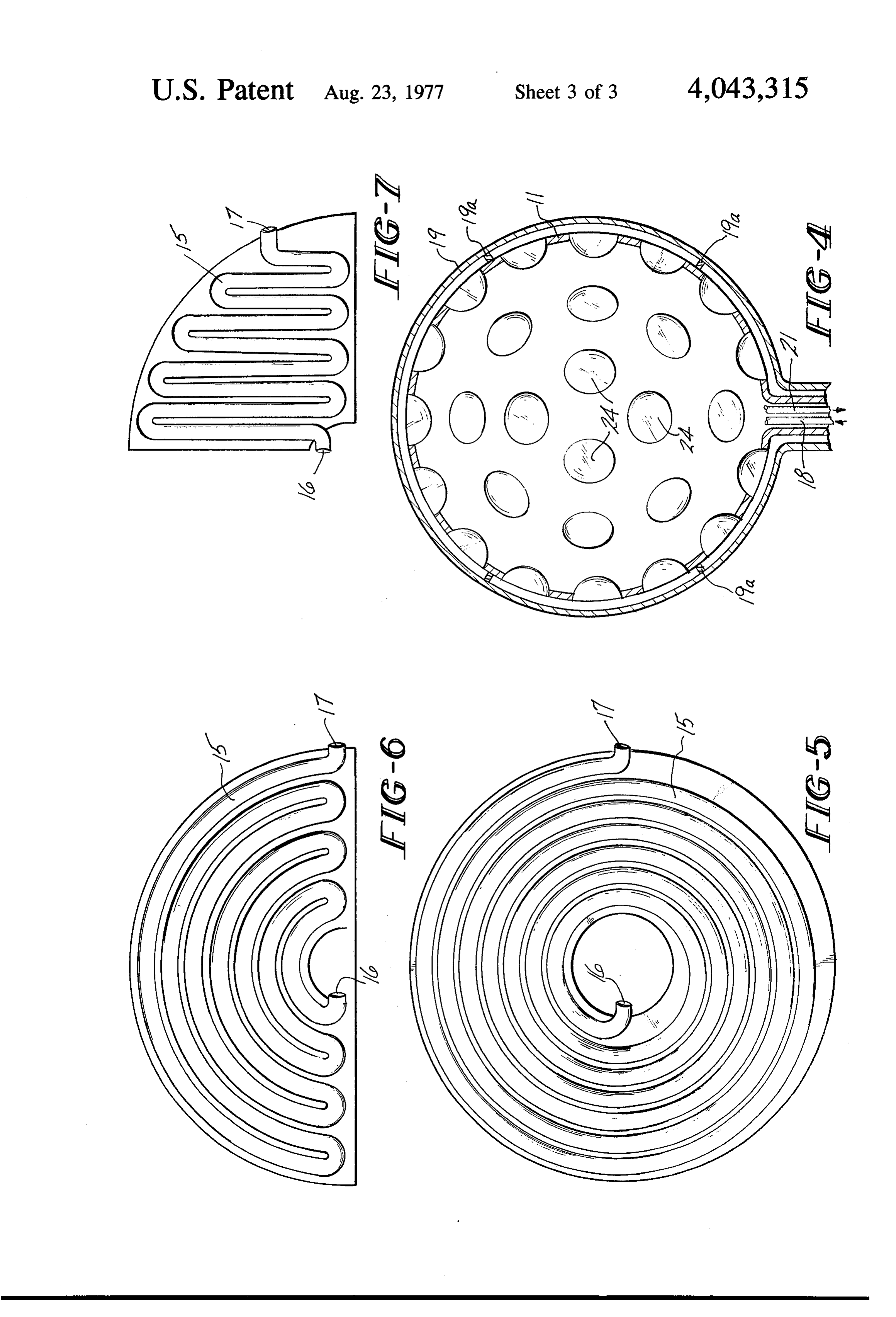
It is a further object of the present invention to pro the present invention showing the outer and inner shells;
vide an inexpensive solar heat collector as aforesaid FIGS. 5, 6 and 7 are plan views of the metal plates which does not require the use of expensive tracking which comprise the heat collecting elements. mechanisms in order to provide efficient operation.
It is a still further object of the present invention to DETAILED DESCRIPTION provide a solar heat collector as aforesaid which is Referring to FIGS. 1, 2 and 3, a plurality of heat omnidirectional, versatile and esthetically acceptable, collecting elements 10 are assembled within inner shell Further objects and advantages of the present inven 35 11 comprising a plurality of intersecting metal plates 12, tion will appear hereinbelow. 13 and 14 placed perpendicular to each other so that the SUMMARY OF THE INVENTION center of all plates, although they are on a separate plane, intersect at a common point. The heat collecting
In accordance with the present invention the forego elements 10 may be assembled from a plurality of metal ing objects and advantages may be readily obtained and plate segments, such as circular plate 12, semi-circular an inexpensive and efficient solar heat collector readily plate segments 13a and 13b, and quadrant segments 14a, provided. The solar heat collector of the present inven 14b, 14c and 14d assembled in any desired manner, as by tion comprises: a transparent, spherical outer shell; a welding or clamping, as shown in FIGS. 2 and 3, spaced spherical inner shell within said outer shell and spaced from inner shell 11 as by support and spacing struts 10a. therefrom containing a plurality of light intensification 45 Each metal plate 12, 13 and 14 contains an internal means, such as a magnifying lenses, spaced along the passageway 15 having a passageway inlet 16 and a pas periphery thereof; a plurality of heat collecting ele sageway outlet 17 for the circulation of a heat transfer ments within said inner shell spaced from the magnify medium as shown in FIGS. 5, 6 and 7. The passageways ing lenses so that maximum light and heat intensity 15 may be prepared by methods known in the art, as by focuses upon said elements; and inlet and outlet headers 50 embossing or stamping two metal plates so that each communicating with said heat collecting elements and plate contains half of the passageway, followed by passing through said inner and outer shells for circula clamping or welding the plates together to form the tion of a heat transfer medium through said heat collect final plate. Other methods may of course be employed, ing elements, In the preferred embodiment magnifica as, for example, welding or otherwise attaching metal tion lenses are employed which are particularly effec 55 tubes to metal plates to provide the desired passageway tive in intensifying that portion of the spectrum having configuration. The passageway outlets 17 are located the highest heat intensity. The heat collecting elements centrally of each plate so that the heat transfer fluid should comprise a circuitous array of passageways to follows a tortuous circuitous path. Passageway inlets 16 provide maximum surface for circulation of a heat communicate with common inlet header 18 passing transfer medium exposed to the magnified light rays, through inner shell 11 and outer shell 19 via inlet open with said passageways being connected to a common ing 20, and passageway outlets 17 communicate with inlet and outlet header communicating with inlet and common outlet header 21 passing through inner shell 11 outlet openings passing through the inner and outer and outer shell 19 via outlet opening 22 for introduction shells. Preferably, the passageways are contained within and circulation of a heat transfer medium through the a plurality of intersecting metal plates. In a preferred 65 heat collecting elements. If desired, the passageways embodiment, a plurality of reflective surfaces are pro may be connected in series so that the heat transfer vided spaced from said outer shell for reflecting light medium passes through all of the coils. Alternatively, rays upon said outer shell. the heat exchange medium may be divided, as by baffles
Page 6scan →
(not shown) so that a portion of the heat transfer me reflected sunlight would be utilized. Concentrated sta dium passes through each coil. tionary or sun-tracking mirrors could also be used. A temperature sensing device 23 is provided commu The device of the present invention may be readily nicating with inlet header 18 and outlet header 21 to employed on a building or along side a building, in regulate the flow of the thermal fluid by sensing the 5 larger or smaller units or in a plurality of interconnected. fluid outlet temperature and making the rate of fluid units. The device is capable of developing very high flow a function of the resultant outlet temperature. temperatures on the order of 750 F. - 900' F. even in Naturally, pump means (not shown) are provided and downstream of the inlet header.
northern climates. The device is versatile, light weight esthetically pleasing and thus offers significant ad
While a particular embodiment of heat collectin O vantages.
elements has been shown, it should be understood that a Naturally, an aqueous heat transfer fluid may be em variety of alternative embodiments may be used within ployed, or ethyleneglycol or pressurized water. Prefer the spirit of the present invention. It is, however, neces ably one employs organic materials capable of with sary to provide a circuitous array of passageways con standing the high temperatures developed. The heated nected to an inlet and outlet header to provide a large 15 fluid may be supplied to any system in which heated exposure surface for the circulatory fluid. The present fluid is utilized. For example, the heated fluid may be embodiment is particularly advantageous since between directed to heat exchangers to provide domestic or the curvature of the coils and the three planes em commercial heating or hot water, or for effecting refrig ployed, both direct beam or diffuse solar radiation from erative cooling or operating heat engines for electricity any angle will impinge upon some parts of the collector 20 generation. Alternatively, an array of solar cells may be. coils with a high degree of efficiency. provided on the plate surfaces, as cells 32 in FIG. 2, for The collector coils 10 are surrounded by a transpar the generation of electricity in a known manner. Also, ent, spherical inner shell 1 containing a plurality of light insulating means may be provided where appropriate, intensification means, such as magnifying lenses 24, as around the inlet and outlet headers. spaced along the periphery thereof for the purpose of 25 This invention may be embodied in other forms or concentrating solar radiation onto the heat collecting carried out in other ways without departing from the elements spaced therefrom. The heat collecting ele spirit or essential characteristics thereof. The present ments are spaced from the lenses so that maximum light embodiment is therefore to be considered as in all re and heat intensity focuses upon the elements, with exact spects illustrative and not restrictive, the scope of the distances depending of course upon the characteristics. 30 invention being indicated by the appended claims, and of the lenses, so that very high temperatures are devel all changes which come within the meaning and range oped in the heat transfer fluid, i.e. on the order of 750 of equivalency are intended to be embraced therein. F. - 900' F. The inner shell may be constructed of any What is claimed is:
suitable material, such as a rigid plastic. . 1. A solar heat collector comprising: a transparent, A transparent, spherical outer shell 19 surrounds the 35 spherical outer shell; a spherical inner shell within said inner shell 11, spaced therefrom as by optional spacers outer shell and spaced therefrom containing a plurality and support means 19a, to protect the lenses from dam of light intensification means spaced along the periph age. In addition, the inner and outer shells protect the ery thereof; a plurality of heat collecting elements collector coils and aid in prevention of loss of heat by within said inner shell spaced from the light intensifica re-radiation from the collector coils, thereby utilizing 40 tion means; and inlet and outlet headers communicating the maximum benefits of the "hot-house effect'. Also with said heat collecting elements and passing through the shells protect the collector coils from loss of heat by said inner and outer shells for circulation of a heat trans convection currents. The outer shell may be con fer medium through said heat collecting elements, structed of any suitable material, such as a rigid plastic. wherein said heat collecting elements comprise a circu If desired, a heated air stream may be utilized by the 45 itous array of passageways contained within a plurality introduction of a controlled airflow through the spaces of metal plates intersecting within said inner shell, said between the inner shell 11 and the heat collecting ele passageways being connected to a common inlet and ments 10 in order to assist the heating process or, alter outlet header.
natively, to cool the collector assembly itself when such 2. A collector according to claim 1 wherein said light cooling is required. 50 intensification means are magnifying lenses and wherein The heat collector of the present invention may be the heat collecting elements are spaced from the magni erected on a stand or tower, as stand 30 shown in FIG. fying lenses so that maximum light and heat intensity 1, to permit the collector to receive direct sunlight, focuses upon said elements.
diffuse sunlight or reflected sunlight from a plurality of 3. A collector according to claim 1 wherein said pas reflective surfaces 31 spaced from outer shell 19, such as 55 sageways are contained in three circular plates perpen mirrors or other reflective surfaces of mirror-like qual dicular to each other and intersecting at a common ity. Although these are not necessary for efficient oper point centrally of said inner shell, wherein each plate is ation, they would be helpful in developing maximum in a separate plane.
efficiency and insure a concentration of sufficient 4. A collector according to claim 1 including a plural square footage of energy impingement to provide a 60 ity of reflective surfaces spaced from said outer shell for particularly high BTU capacity. These reflective de reflecting light rays upon said outer shell. vices would include, but need not be limited to, highly 5. A collector according to claim 1 including a tem reflective foil surfaces on roofs, walls or other available perature sensing device communicating with the inlet surfaces, an array of fixed concentrated solar beam and outlet headers for regulating the flow of the heat reflective devices at an assorted mix of angles so that 65 transfer medium through the heat collecting elements. regardless of the sun's azimuth or direction sufficient is . . . . . .
Provenance
- Collection
- Patents citing this work
- Pages
- 6
- Method
- pdftotext (the PDF's own text layer) + pdftoppm 300dpi page scans
- Patent office record
- patents.google.com →
- Source
- Google Patents citing-documents table
- Assignee
- Cooper Nathan E
- Published
- 1977-08-23
- Transcribed from
- patentimages.storage.googleapis.com →