

patent · US4180055A
Solar-heat collector
25 December 1979
Text
Page 1scan →
United States Patent (19)
Hudnal
54). solar-heat collector
76 Inventor: Walter E. Hudnal, 2157 W. 236th
Pl, Torrance, Calif. 90501
51 Int. C.’................................................. F24, 3/02 52 U.S.C. ...................................... 126/446; 165/76;
3,227,153 1/1966 Godel et al. ......................... 126/271 3,672,446 6/1972 Tibbetts et al. ... ... 165/183 4,011,856 3/1977 Gallagher ... ... 126/27 4,026,267 5/1977 Coleman. ... 126/270 4,026,273 5/1977 Parker ... ... 126/271 4,036,209 7/1977 Press ..... ... 126/271 4,081,289 3/1978 Campbell ............................. 126/271 Primary Examiner-James C. Yeung
Attorney, Agent, or Firm-Francis X. LoJacono
Qaretzer
A solar-heat-collector apparatus providing a means for gathering and concentrating solar radiation at a maxi mum collecting rate, regardless of the incident angle of the solar radiation impinging on the apparatus. The apparatus comprises an outer housing and an inner housing arranged in spaced relation to each other-forming an insulating gap therebetween. Dis posed within the second housing is a continuously ar ranged solar-pipe system on which is affixed compati ble, molded, heat-absorbing, finned bodies wherein the fin members thereof extend radially outward in a longi tudinal array of panels arranged at various angular de grees about the pipe to increase the radiation impinging area, so as to receive the maximum solar energy as it enters through either side of the transparent housing at any given angular displacement. The apparatus can be positioned to receive solar radiation simultaneously from both sides when a parabolic reflector unit is so positioned to reflect the solar radiation to the side not directly exposed to solar radiation.
5 Claims, 8 Drawing Figures
Drawings
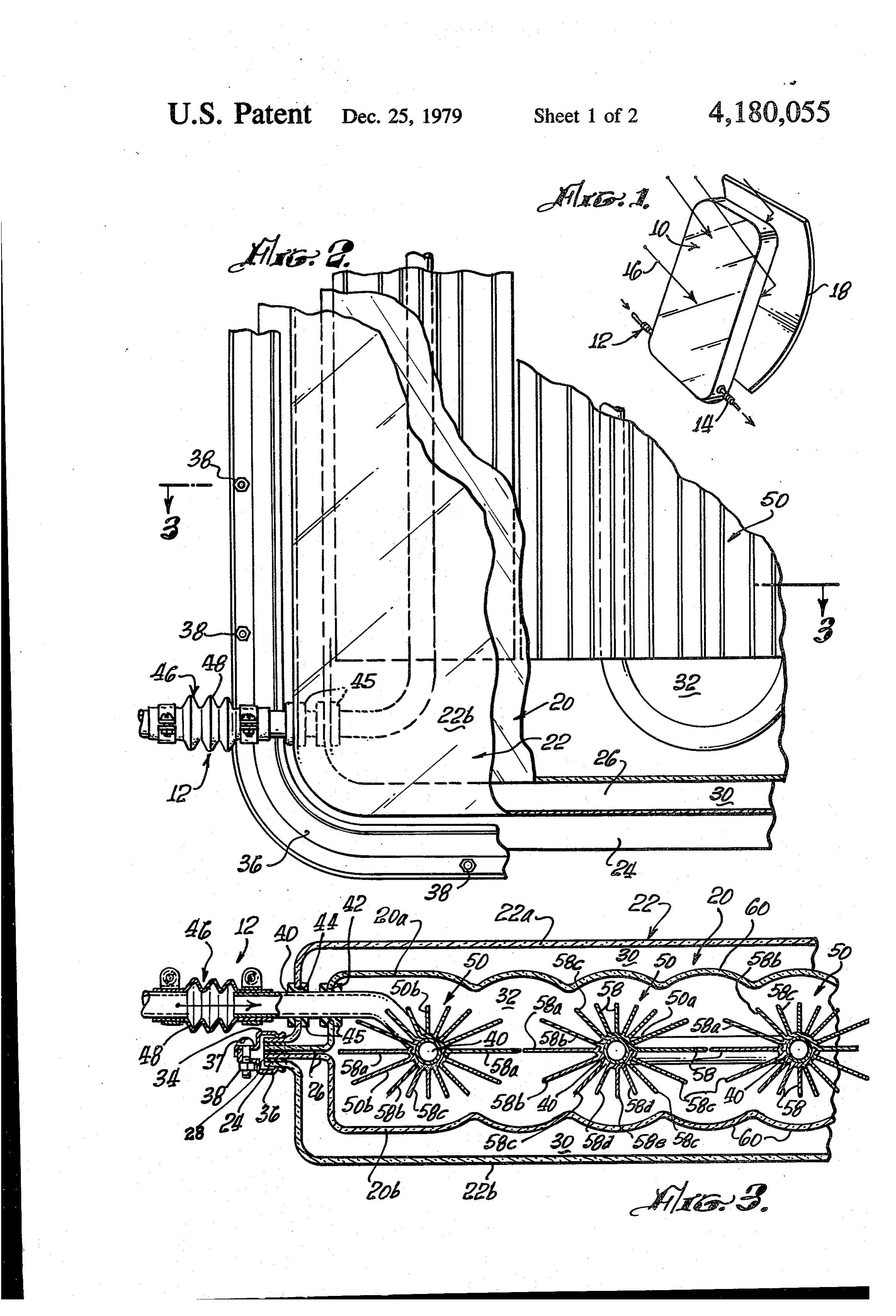
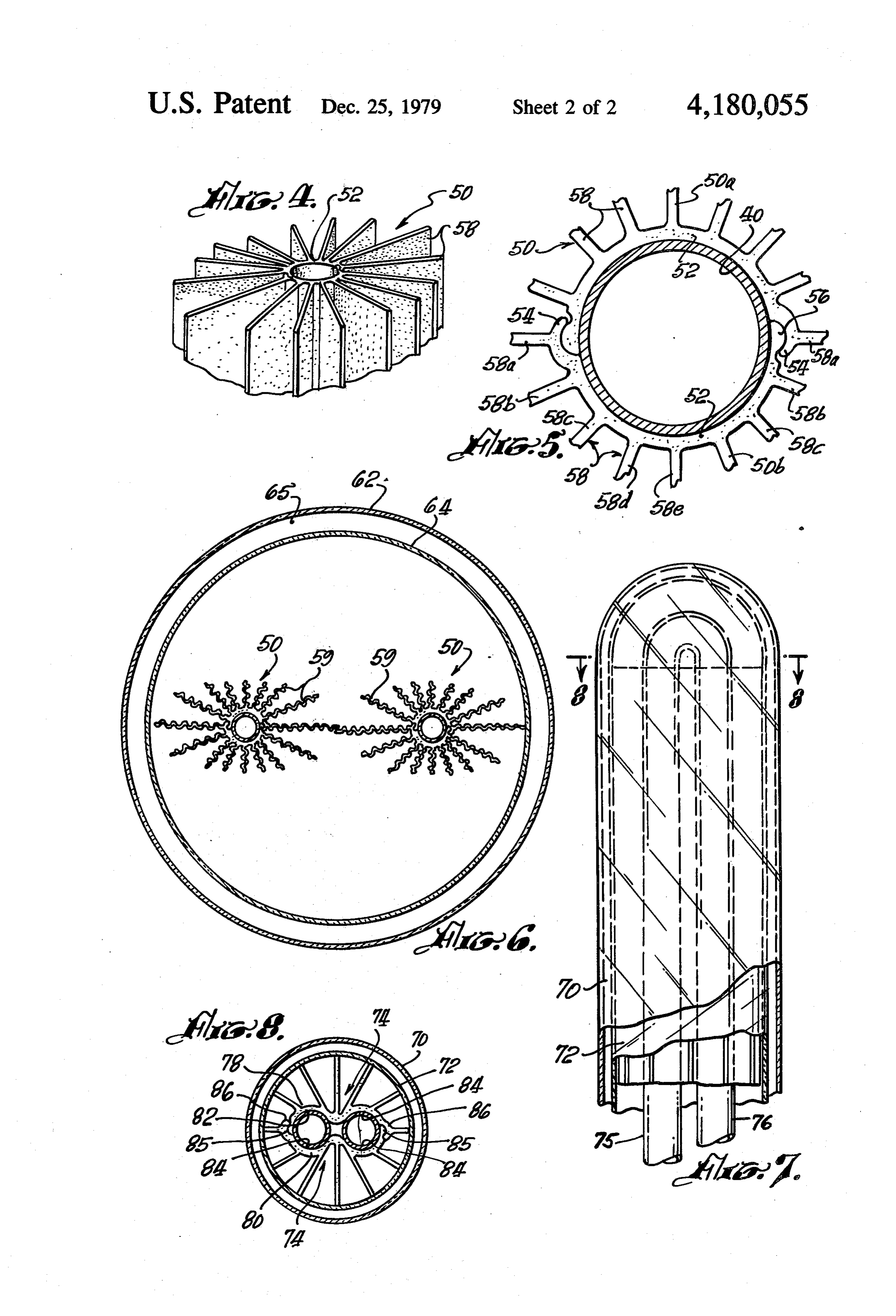
FIG. 4 is a perspective view of one end of a solar bers 34 and 36 fastened together by nuts and bolts 38 radiation-collector molding member wherein the two and 39, respectively.
Page 2drawing sheetscan →
Page 3drawing sheetscan →
Page 4scan →
having segmented domes, thus creating radiation-focus
SOLAR-HEAT COLLECTOR ing members to collect wide-angle incoming radiation. A second outer housing-also of a clear material-is
BACKGROUND OF THE INVENTION superposed over the inner housing; and it, too, is sub 1. Field of the Invention stantially sealed wherein an insulating "dead-air" space This invention relates generally to a solar-heater de areformed is between the two housings. The clear housings arranged so that radiation is allowed to pass through vice, and more particularly to a solar-heat collector having unique solar-energy-collector plates-providing at Hence, all angles, thus striking the radiating fin members, a substantially increased absorbing area which maxi 10 this device,reflection allowing devices are readily compatible with additional radiation from both the mizes the heat transfer to the flowing fluid within the front or back sides, when placed in operating condition. heater.
2. Description of the Prior Art OBJECTS AND ADVANTAGES OF THE As is well known in the art, various problems and INVENTION difficulties are encountered in providing suitable means 15 The present invention has for an important object a for total absorption of the rays of the sun to the flowing provision wherein a solar-heated-fluid-collecting device fluid within a solar-collection system. There is a need to is so designed wherein the maximum solar energy is provide a larger exposed area capable of utilizing solar absorbed under the most simple operating conditions. radiation without substantially increasing the size and It is another object of the present invention to pro cost of the device. 20 vide a solar heated-fluid collector having an improved Many types of solar heaters or collectors are pres construction of clear inner and outer housing units ar ently in use in the various geographical locations which ranged to define an insulated space disposed therebe have different requirements. However, these devices tween, wherein the inner housing includes a plurality of have features that restrict their use or location; and they are complicated to install and expensive to maintain, 25 dome-shaped, radiation concentrators wherein substan tially all of the solar radiation penetrating the housing is since they are generally exposed to the various weather converted to heat.
conditions. It is still another object of the invention to provide a Such examples of prior and known solar fluid heaters solar heated-fluid-collector device that includes a pair are disclosed in U.S. Pat. No. 3,974,824 to Ronald H. 30 of interlocking molds having a plurality of radially Smith. The Smith device utilizes a cylindrical reflector extending fin members that are disposed longitudinally with a spirally extending section for concentrating solar to the pipe, and have various angular displacements and energy on an axially disposed absorber. widths so as to provide a maximum overall exposure to Another type of solar fluid heater is disclosed in U.S. the incoming solar radiation.
Pat. No. 4,026,273 to Blaine F. Parker. This device It is a further object of the invention to provide a includes a radiation trap for concentrating solar radia 35 device of this character wherein both sides of the hous tion which has been focused on or near a line at the ing are adapted to receive solar radiation, and wherein center of a transparent pipe assembly. One of more sets a reflector device combined therewith allows for in of reflective fins are disposed in direct heat-exchanging creased radiation.
contact with the fluid to be heated. It is still a further object of the invention to provide a A further solar device is shown and described in U.S. device of this character that is easy to install, service Pat. No. 2,907,318 to A. E. Awot. and maintain.
However, there is still needed a solar fluid-heater Still another object of the invention is to provide a apparatus that is designed for a more universal applica solar heater that is relatively inexpensive to manufac tion with maximized capabilities of absorbing solar-radi 45 ture, and simple and rugged in construction. ant energy with the simplest components. The characteristics and advantages of the invention SUMMARY OF THE INVENTION are further sufficiently referred to in connection with the accompanying drawings, which represent one em
The present invention comprises a solar-heat collec bodiment. After considering this example, skilled per tor wherein a fluid, tubular, heat-receiving pipe is ar 50 sons will understand that variations may be made with ranged having positioned and engaged thereon a plural out departing from the principles disclosed; and Icon ity of longitudinal, fin-like plate members which radiate template the employment of any structures, arrange outwardly and are generally formed of an aluminum ments or modes of operation that are properly within extrusion. The longitudinal plates are integrally formed the scope of the appended claims. by two interlocking and continuous mold sections 55 BRIEF DESCRIPTION OF THE DRAWINGS which are coupled together about the outer periphery of the conducting pipe. The objects of the present invention and the atten In the preferred embodiment, each fin is provided dant advantages thereof may be better understood by with a predetermined width at various angular degrees, reference to the following drawings, which are for whereby the overall absorbing area is substantially in illustrative purposes only, wherein: creased in order to provide maximum solar-radiation FIG. 1 is a diagrammatic, perspective view of a solar impringement thereon, so as to transfer the solar energy heated-fluid collector having a reflector means posi directly into the wall of the fluid-carrying pipe enclosed tioned relative thereto;
within the elongated molds. FIG. 2 is an enlarged plan view of a portion of the Further, the finned molds and pipe are disposed in a 65 present device with sections broken away to illustrate dual-arranged housing-that is, an inner housing encap various elements therein;
sulates the fins and pipe in a substantially sealed envi FIG. 3 is a cross-sectional view taken substantially ronment wherein the walls of the housing are shaped along line 3-3 of FIG. 2;
Page 5scan →
FIG. 4 is a perspective view of one end of a solar bers 34 and 36 fastened together by nuts and bolts 38 radiation-collector molding member wherein the two and 39, respectively.
sections are coupled together; Disposed within the inner housing 20 is a continuous FIG. 5 is an enlarged, transverse, cross-sectional line of pipe 40 which enters through openings 42 and 44 view of a pipe having the solar-radiation-collector of the respective housings 20 and 22. Each opening is molding secured thereto; provided with a sealing grommet 45 with similar open FIG. 6 is a sectional view of an alternative arrange ings and seals located therein to allow the pipe or tubing ment of a solar housing having a pair of solar-radiation 40 to exit said housings at the opposite side, as seen in collection units disposed therein; FIG. 1.
FIG. 7 is a plan view of a portion of an alternative 10 Accordingly, the pipe or tubing 40 is bent back on embodiment of a solar-heated-fluid collector having a itself so as to provide juxtaposed parallel conduits differently arranged solar-radiation collector unit posi through which flows fluid-preferably water. Thus, tioned therein; and water enters through inlet 12, and travels through pipe FIG. 8 is a cross-sectional view taken along line 8-8 40 and discharges through outlet 14. Both outlets are of FIG. 7 thereof. 15 adapted to be coupled to a closed water system (not
Detaileed description of the
shown). As an example, a coupling means 46 is shown in
Preferred embodiment
FIGS. 2 and 3. This coupling means can be any known device that is flexible like a bellows-type hose 48.
Referring now to FIGS. 1 through 5, and more par Accordingly, the object is to collect as much incom ticularly to FIG. 1, there is shown a solar-heated-fluid 20 ing solar radiation with the housings and concentrate collection device, generally indicated at 10, having inlet that energy to impinge on the continuously arranged and outlet means designated at 12 and 14, respectively. pipe 40, wherein the water is efficiently heated as it As noted, the collection device is positioned angularly passes through. Thus, in order to provide and enhance relative to the incident impinging solar radiation, indi the heating of the water at a faster rate with more effi cated by arrows 16. Because of the specific construction 25 ciency, there is included a solar-heat-absorbing-collec of this device, which will be hereinafter described in tor member mounted to each elongated parallel length detail, a reflector means, such as the parabolic reflector of juxtaposed pipe. This solar-heat-absorbing-collector 18, can be readily positioned to provide a means to member is designated at 50 and comprises two identical reflect solar radiation to the rear-facing surface of the half sections of extruded-aluminum-molded jackets 50a collector device-adding to its ability to be highly effi 30 and 50b. Each half section includes a main, longitudinal, cient with a low rate of solar-energy loss. semicircular body 52, which-when coupled toge The solar-heated-fluid-collection device 10 comprises ther-encapsulates the longitudinal pipe sections. The an inner housing means indicated at 20, and an outer free longitudinal edges of body 52 are further provided housing means indicated at 22, the inner housing 20 with coupling means, wherein one edge is formed with being supported within the outer housing whereby a 35 a locking tongue member 54, and the other edge is "dead' air space or gap is defined-creating a clear formed as a longitudinal rib 56 arranged to be received insulation means which allows solar energy to freely in the locking tongue of a mating body 52, as seen in pass from the outer housing into the inner housing, each FIG. 5. That is, when the half sections of the solar-heat housing being formed from a clear glass or plastic mate absorbing collector are coupled together, the locking rial, or any suitable combination thereof. tongue 54 of the first half section 50a couples with the Outer-housing means 22 in this particular arrange mating rib member 56 of the second half section 50b. ment comprises two oppositely positioned half-wall Further, however, each body includes a plurality of sections 22a and 22b. These half-wall sections generally integrally formed heat-absorbing fin members defined take a rectangular form, as shown in FIG. 1, and are by elongated plates 58 wherein each plate or fin extends fastened together along the peripheral edges formed by 45 the full length of body 52.
a continuous flange member 24. The exposed surface of The fin members 58 are arranged so as to have their each section is preferably flat, as shown, but may be width extend radially outward from body 52 at various formed in various configurations that cause the imping angular degrees. This allows for greater exposed area ing rays to be concentrated within the housing itself. for impinging radiation-thus providing greater heat The inner-housing means 20 is also provided with 50 absorption. It should be further noted that additional oppositely arranged half-wall sections 20a and 20b, absorbing area is provided by varying the widths of the respectively, with each half-wall section 20a and 20b adjacent fin members, so that fin 58a has the largest having peripheral flange members 26. Thus, as shown in width for greater exposure-the adjacent fin 58b being FIG. 3, flange members 26 are positioned between slightly smaller in width, and fin members 58c, 58d and flange members 24, wherein annular gasket members 28 55 58e being even smaller in width. This arrangement al are interposed therebetween to seal the flanges in their lows for maximum area exposure as the direction of the respective positions-preventing, to some extent, ambi sun travels during the day.
ent air from reaching chambers 30 formed between the Accordingly, the sun's rays are absorbed in the radial inner and outer housings, and from reaching the solar fin members 58, thus transferring the heat directly into chamber 32 formed by the inner-housing wall sections. the wall of pipe or tubing 40.
Chambers 30, encapsulating inner housing 20, define It is further contemplated that each solar-absorbing a "dead'-air insulating space wherein the inner housing section will be anodized or coated with black heat is not affected by rapid, outer, ambient-temperature absorption material.
changes. In order to provide even greater concentration of the To provide a means for fastening housings 20 and 22 65 entering solar rays, inner housing sections 20a and 20b in their respective sealed relationship, there is included are formed with a plurality of contiguously disposed securing means mounted to the peripheral flange mem and elongated domes 60, defining radiation-concentrat bers, said means being shown as a pair of frame mem ing means. Each dome 60 causes the incoming rays to be 6 focused on a different area of the exposed fins, thus a solar-heat-absorbing-collector member removably providing the optimum of transmitted rays from the mounted to each elongated parallel length of pipe outer housing into the chamber 32. section, in order to transfer the solar heat into said Referring now to FIG. 6, there is shown an alterna pipe sections;
tive arrangement of the outer and inner housings, 5 wherein said solar-heat-absorbing-collector member wherein the outer and inner housings 62 and 64, respec comprises a first half section of an elongated tively, are formed as elongated tubular housings coaxi molder jacket, a second, matching, half section of ally aligned, one within the other, and having an insu an elongated molder jacket, wherein each jacket lated "dead-air' chamber or space 65 positioned there includes a plurality of longitudinally formed fin between. Here again, it is contemplated that each hous 10 members radially disposed about the pipe, in order ing will be constructed of known materials that allow to absorb and transfer said solar radiation passing the solar radiation to pass therethrough and strike the through said housings, wherein said molded jackets solar-heat-absorbing-collector members 50. The comprise a main, longitudinal, semicircular body molded jackets are as previously described heretofore. having said elongated fin members integrally In addition, it is further contemplated that a vacuum 15 formed as part thereof, said fin members extending could be provided in chamber 65 as well as chamber 66 radially outward at different angular degrees, and of the inner housing 64. In this illustration, each solar wherein the width of each fin member varies ac heat-absorbing collector member 50 is designed cording to the angular displacement thereof, and wherein the longitudinal fin members are corrugated, as coupling means formed on said jackets and ar indicated at 59. Thus, the fin area is still further in 20 ranged to couple the half sections together, thus creased to receive a maximum amount of solar radiation enclosing said elongated pipe sections therein; so as to be readily transferred to the respective pipe. an inlet and an outlet means connected to said contin In FIG. 7-which is another modified form of the uous conduit to allow said fluid flow to enter and invention-there is shown outer and inner housings 70 discharge therefrom; and and 72, respectively. In this modified arrangement, the 25 sealing means disposed between said inner and outer molded jackets 74 are designed to receive two longitu housings, and between said housings and said con dinally disposed pipes 75 and 76. That is, each half-sec duit;
tioned body member 78 and 80 comprises dual, adja an insulation chamber interposed between said inner cent, semicircular channels 82 and 84 wherein the free and outer housings;
edge of channel 82 includes a longitudinal rib member 30 said outer housing comprising a pair of oppositely 85, and the outer free edge of channel 84 is provided positioned half-wall sections; with locking tongue 86. Thus, the sections snap to wherein said inner housing comprises a pair of oppo gether in a clamping arrangement, as seen in FIG. 8. Fin sitely positioned half-wall sections, said sealing members are also included, as previously described. means being interposed between each of said half The invention and its attendant advantages will be 35 wall sections of both housings; understood from the foregoing description, and it will said half-wall sections of said inner housing including be apparent that various changes may be made in the radiation-concentrating means to concentrate and form, construction and arrangement of the parts of the focus radiation impinging on said fin members; and invention without departing from the spirit and scope securing means arranged to secure said wall sections thereof or sacrificing its material advantages, the ar and said sealing means together. rangement hereinbefore described being merely by way 2. A solar-heat-collector device as recited in claim 1, of example; and I do not wish to be restricted to the wherein said radiation-concentrating means comprises a specific form shown or uses mentioned, except as de plurality of contiguously disposed, elongated, dome fined in the accompanying claims. members arranged above and below said solar-heat I claim: 45 absorbing-collector members.
1. A solar-heat-collector device having a continuous 3. A solar-heat-collector device as recited in claim 2, conduit of a plurality of parallel, juxtaposed, longitudi wherein there is included a reflector means to be posi nal pipe sections for passage of fluid therethrough, said tioned adjacent the side of said device not positioned to device comprising: receive direct solar radiation. an inner, substantially sealed housing having said 50 4. A solar-heat-collector device as recited in claim 3, conduits positioned therein, said housing being wherein said housings are formed from glass. formed to allow passage of solar radiation there 5. a solar-heat-collector device as recited in claim 3, through; wherein said housings are formed from plastic materials an outer, substantially sealed housing arranged to capable of allowing solar radiation to pass there encapsulate said inner housing, and formed to 55 through.
allow passage of solar radiation therethrough;
Provenance
- Collection
- Patents citing this work
- Pages
- 6
- Method
- pdftotext (the PDF's own text layer) + pdftoppm 300dpi page scans
- Patent office record
- patents.google.com →
- Source
- Google Patents citing-documents table
- Assignee
- Hudnall Walter E
- Published
- 1979-12-25
- Transcribed from
- patentimages.storage.googleapis.com →