

patent · US4056093A
Solar heater
1 November 1977
Text
Page 1bibliographic recordscan →
United States Patent (19)
Barger
54 SOLAR HEATER
Inventor: Harold E. Barger, Paxton, Nebr.,
51 Int. Cl. ................................................. F24, 3A02
1,093,498 4/1914 Thring ................................. 126/271 1,672,750 6/1928 Christiansen......................... 126/271 1969,839 8/1934 Goddard .............................. 126/271 3,321,012 5/1967 Hervey ................................. 126/271 3,587,559 6/1971 Nonaka ................................ 126/271
FOREIGN PATENT DOCUMENTS
30,994 8/1966 Japan .................................... 126/271 Primary Examiner-John J. Vrablik
Attorney, Agent, or Firm-Clarence A. O’Brien; Harvey B. Jacobson
A solar heating unit is provided including an upwardly
opening generally hemispherical double wall boiler including spaced inner and outer hemispherical walls defining a closed chamber therebetween in which to receive a liquid to be heated. An upwardly convex spherical lens structure is supported over the boiler and comprises a closure for the area enclosed within the boundaries of the inner hemispherical wall of the boiler and the lens assembly or structure functions to direct light rays incident thereon onto the inner wall of the boiler. The solar heater additionally includes a hollow downwardly opening transparent hemispherical cover of generally the same radius of curvature as the boiler and which is secured over the lens assembly in out wardly spaced position relative thereto with the center of curvature of the cover substantially coinciding with the center of curvature of the lens assembly. Water or other liquid inlet and outlet structure is provided on a second form of the invention for admitting liquid to be heated into the interior of the boiler between the inner and outer plates thereof and for withdrawing heated liquid from within the boiler.
4 Claims, 2 Drawing Figures
Drawings
Page 2drawing sheetscan →
Page 3scan →
Detaled description of the
Solar heater invention
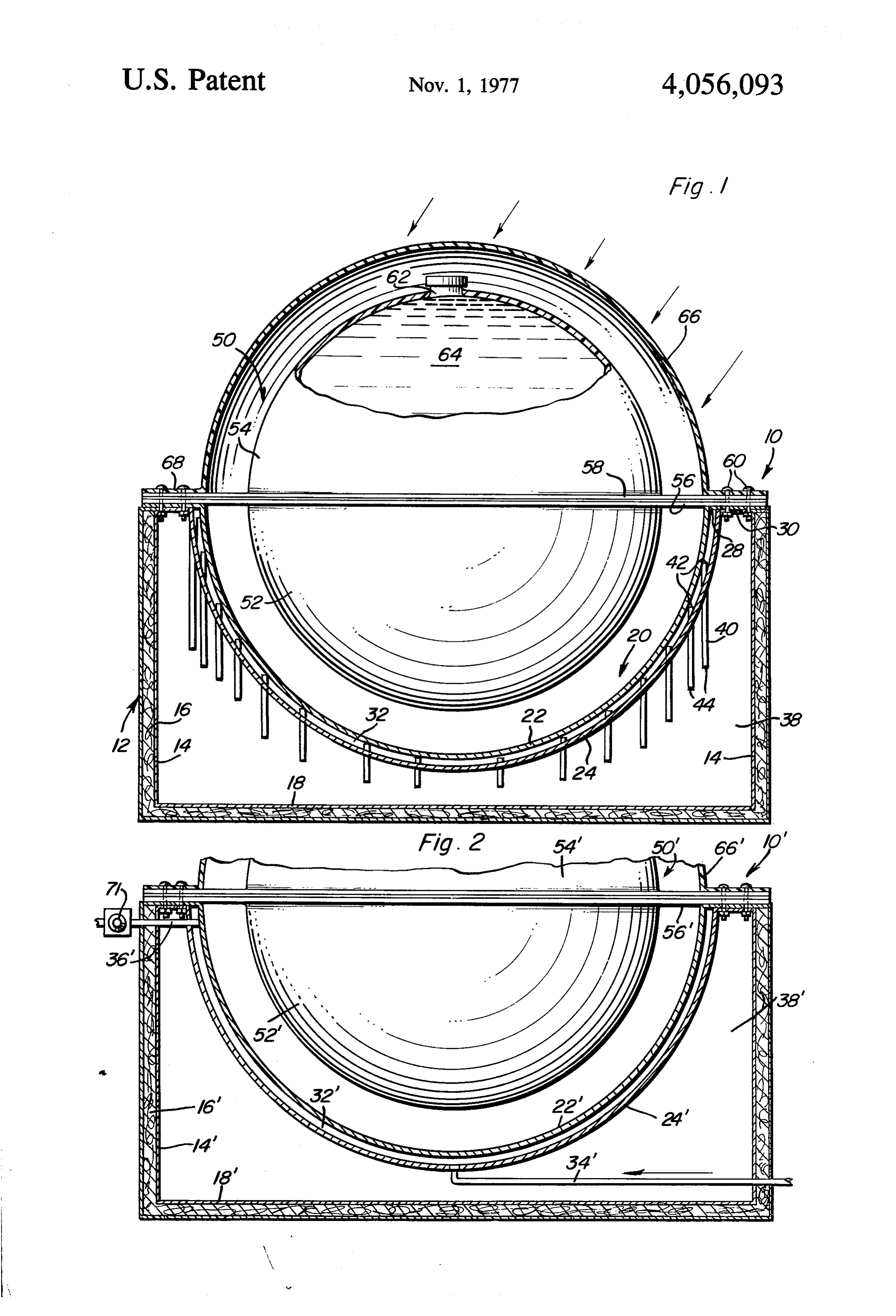
BACKGROUND OF THE INVENTION Referring now more specifically to the drawings the Many different forms of solar heaters have been here- 5 numeral 10 generally designates a first form of solar tofore provided for the purpose of heating a working heater constructed in accordance with the present in liquid. However, most stationarily supported solar heat vention. The solar heater 10 includes an upwardly ers operate at extremely low efficiency during the first opening generally rectangular housing referred to in three or four hours after sunrise and the three or four general by the reference numeral 12 including intercon hours preceding the setting of the sun and enjoy reason 10 nected upstanding peripheral walls 14 provided with able efficiency only during the several hours bridging insulation 16 and having an insulated bottom wall 18 the time at which the sun is at its highest point. Exam extending between and interconnecting the lower ends ples of various forms of solar heaters designed to enjoy of the peripheral walls 14.
greater efficiency throughout the entire period between An upwardly opening hemispherical boiler assembly sunrise and sunset are disclosed in U.S. Pat. Nos. 15 referred to in general by the reference numeral 20 is 2,455,834, 2,636,129, 2,872,915, 2,918,023 2,993,125, provided and includes closely radially spaced inner and 3,125,091 and 3,391,688. s outer hemispherical plates 22 and 24 joined at corre However, these previously patented solar heaters do sponding marginal edge portions thereof as at 28 and not provide maximum efficiency with relatively simple supported from a mounting plate structure 30 secured structure which may be produced at a low cost. 20 over and supported from the upper ends of the periph BRIEF DESCRIPTION OF THE INVENTION eral walls 14 and having a central opening formed therein in which to receive the marginal portions of the
The solar heater of the instant invention utilizes a outer plate 24.
simple convex hemispherical boiler assembly in which The space 32 defined between the plates 22 and 24 liquid is disposed for absorbing heat energy from the 25 defines a water chamber in which water, or other fluid sun. In a first form of the invention the boiler is sealed to be heated, is disposed and the fluid is admitted into and in a second form liquid to be heated may be pumped the space through any suitable inlet, not shown. through the boiler. A sunlight concentrating lens struc The interior 38 of the housing 12 inwardly of the ture of hemispherical design is provided over the boiler walls 14 and 18, below the mounting plate structure 30 to concentrate the sun's rays on the boiler assembly 30 and outwardly of the boiler assembly 20, defines a throughout the period from sunrise to sunset. Also, chamber which may be filled with any suitable fluid downwardly opening hollow hemispherical cover is such as a eutectic solution and a plurality of "heat provided over the lens assembly to reduce heat losses. pipes' 40 include upper portions 42 thereof disposed in The main object of this invention is to provide a solar the chamber 32 and lower portions 44 thereof disposed heater which will be capable of efficient operation 35 within the interior 38 of the housing 12. The "heat throughout substantially the entire time between sunrise pipes' 40 are sealingly secured through the outer plate and sunset on a cloudless day. 24.
Another object of this invention, in accordance with Aspherical lens assembly referred to in general by the the immediately preceding object, is to provide a solar reference numeral 50 and including a pair of hollow heater which may be utilized in conjunction with a heat 40 hemispherical bodies 52 and 54 opening toward each absorptive and retaining material for the purpose of other is provided. The bodies 52 and 54 include diamet storing appreciable quantities of heat for use between ric mounting plate portions 56 and 58 at the open sides the hours of sunset and sunrise. thereof and the mounting plate portions 56 and 58 are Still another important object of this invention is to secured together in juxtaposition in fluid-tight sealed provide a solar heater which may be usable in numerous 45 engagement and the mounting plate portions 56 and 58 environments where the generation and storage of heat are secured to the mounting plate structure 30 by means is desired. of suitable fasteners 60. The center of curvature of the A final object of this invention to be specifically enu spherical lens assembly 50 coincides with the center of merated herein is to provide a solar heater in accor curvature of the inner and outer walls of the boiler dance with the preceding objects and which will con 50 assembly 20 and the upper hemispherical body 54 in form to conventional forms of manufacture, be of sim cludes a removably capped inlet neck 62 through which ple construction and easy to use so as to provide a de a transparent liquid 64 may be introduced into the lens vice that will be economically feasible, longiasting and assembly 50.
relatively trouble free in operation. In addition, a downwardly opening hollow hemi These together with other objects and advantages 55 spherical and transparent cover 66 including a mount which will become subsequently apparent reside in the ing plate portion 68 extending about its open side is details of construction and operation as more fully here secured over the lens assembly 50 in spaced relation inafter described and claimed, reference being had to relative thereto with the mounting plate portion 68 also the accompanying drawings forming a part hereof, secured to the mounting plate structure 30 by means of wherein like numerals refer to like parts throughout. 60 the fasteners 60. The cover 66 is transparent and may also act as a first lens element in addition to a means to
BRIEF DESCRIPTION OF THE DRAWINGS insulate the lens assembly 50 against a heat dissipation FIG. 1 is a vertical sectional view substantially upon therefrom.
a plane passing through the center of a first form of In operation, the sun's rays incident upon the cover 66 solar heater constructed in accordance with the present 65 and the lens assembly 50 are concentrated onto the invention; and inner plate 22 of the boiler assembly 20 thereby heating FIG. 2 is a fragmentary vertical sectional view similar the inner plate 22 and the water or other liquid within to FIG. 1 but of a modified form of solar heater. the chamber 32. The "heat pipes' 40 rapidly conduct 4 heat from the liquid in the chamber 32 to whatever heat and equivalents may be resorted to, falling within the absorbing and storing medium is disposed within the scope of the invention.
interior 38 of the housing 12 and any suitable means, What is claimed as new is as follows: such as additional "heat pipes' may be used to with 1. In combination, an upwardly opening generally draw heat from the heat storing medium disposed hemispherical double wall boiler including closely radi within chamber 38. ally spaced inner and outer hemispherical walls defining With reference now more specifically to FIG. 2 of the a closed chamber therebetween in which to receive a drawings, there will be seen a modified form of solar liquid to be heated, a hollow transparent spherical lens heater referred to in general by the reference 10' and body of smaller outside diameter than the inside diame which includes many of the structural features of the 10 ter of said boiler, supported concentrically from the solar heater 10. Those features of the heater 10' which upper peripheral portion of said boiler and closing the are identical to corresponding elements of the heater 10 latter from above and filled with a transparent liquid, a are designed by similar prime reference numerals. downwardly opening hemispherical and transparent The basic difference between the heaters 10 and 10' is hollow cover secured over said transparent spherical that the heater 10' does not include the equivalent of the 15 lens in spaced relation thereto and with the centers of "heat pipes' 40. Further, an upper outlet pipe 36' is provided and includes a manually adjustable thermostat curvature spherical of said spherical lens, inner and outer hemi walls and said cover substantially coinciding.
valve 71 for controlling the flow of liquid from the 2. The combination of claim 1 including an upwardly chamber 32, and a lower inlet pipe 34' is provided and opens into the lower portion of chamber 32". A suitable 20 opening housing across whose open top said boiler is secured with the exterior of said boiler spaced from the heat transfer liquid may be pumped through the cham inner surfaces of said housing and thereby defining a . ber 32 in order to convey the heat absorbed within heat storage area in which a heat absorbing and storing chamber 32' to be used at a remote point with which the material may be housed, and heat exchange means in ends of the lines 34 and 36' remote from the chamber 32' are communicated. The thermostat 71 insures that 25 cluding first and second portions thereof disposed liquid will not be discharged from the chamber 32" within said area and chamber and operative to convey through the pipe 36 until such time as the liquid has heat from the former to the latter.
been heated to a predetermined minimum temperature. 3. The combination of claim 1 including means for Otherwise, the operation of the solar heater 10' is simi admitting fluids to be heated into a lower portion of said lar to the operation of the solar 10. 30 closed chamber and withdrawing heated fluids from an The foregoing is considered as illustrative only of the upper portion of said chamber.
principles of the invention. Further, since numerous 4. The combination of claim 3 including a thermostat modifications and changes will readily occur to those ically actuated valve controlling the flow of fluids skilled in the art, it is not desired to limit the invention through said means for withdrawing heated fluids from to the exact construction and operation shown and 35 said chamber. k s described, and accordingly all suitable modifications
Provenance
- Collection
- Patents citing this work
- Pages
- 4
- Method
- pdftotext (the PDF's own text layer) + pdftoppm 300dpi page scans
- Patent office record
- patents.google.com →
- Source
- Google Patents citing-documents table
- Assignee
- Barger Harold E
- Published
- 1977-11-01
- Transcribed from
- patentimages.storage.googleapis.com →