

patent · US4279241A
Solar heat absorbing and radiating wall
21 July 1981
Text
Page 1bibliographic recordscan →
United States Patent (19)
Himes
54). SOLAR HEAT ABSORBING AND
RADATING WALL
Inventor: John W. Himes, P.O. Box 1617, Taos,
Int. Cl............................. F24J 3/02; F28F 7/00 52 U.S. Cl. .................................... 126/431; 126/447;
842,658 1/1907 Haskell ................................. 126/449 3,314,414 4/1967 Rowekamp. . . 126/450 3,893,506 7/1975 Laing ...... . 126/450 3,972,317 8/1976 Gallagher ............................ 126/450 3,987,784 10/1976 Godrick .............................. 126/450 3,996,919 12/1976 Hepp .................................... 126/429 4,015,585 4/1977 Fattor ................................... 126/438 4,016,861 4/1977 Taylor .................................. 126/449 4,026,267 5/1977 Coleman .............................. 126/449 4,058,109 11/1977 Gramm ................................ 126/422 4,083,360 4/1978 Courvoisier et al. . . 126/447 4,084,574 4/1978 Golay .............. . . 126/449 4,108,155 8/1978 Koizumi et al. ..................... 126/429
4,114,593 9/1978 Guertin ................................ 126/450 4,149,903 4/1979 Lindmayer ........................... 126/417 4,184,476 l/1980 McArthur ............................ 126/429 4,188,941 2/1980 Hopkins ............................... 126/449
OTHER PUBLICATIONS
Miller, Solar Heat Pipe, Mechanix Illustrated, Dec.,
Primary Examiner-Daniel J. O'Connor
Attorney, Agent, or Firm-James A. Wong
Building construction having at least one, wall with an inner surface and an outer surface comprising in combi nation therewith a heat energy absorbing member dis posed outwardly of the outer surface for absorbing solar heat energy, heat radiating members disposed inwardly of the inner surface, and heat transfer elements extend ing through the wall, the heat transfer elements being in contact with both the heat energy absorbing member and the heat radiating members whereby solar heat energy absorbed by the heat energy absorbing member may be transferred therefrom by the heat transfer ele ments to the heat radiating members to heat the interior of the building construction.
5 Claims, 4 Drawing Figures
is V w . . . . . . . .
ps--- - M -- -
Y r
Drawings
Page 2drawing sheetscan →
Page 3scan →
Solar heat absorbing and radating
to usable heat for interior spaces suitable for habitation or other purposes.
WALL It is also an object of the present invention to provide BACKGROUND OF THE INVENTION a new and improved building structure whereby solar 5 energy may be absorbed, transferred into the building 1. Field of the Invention by heat conducting elements, and given off inside the The present invention relates to a building construc building by heat radiating members.
tion or portion thereof which is of such character that It is another object of the present invention to pro solar energy falling thereon may be readily and effi O vide a new and improved building structure of rather ciently converted to interior heating purposes. More simple but functional character.
particularly, building constructions of the type with It is still another object of the present invention to which the present invention is most likely to be associ provide a new and improved building structure ated are believed to be found in Class 126, Subclasses whereby solar energy may be used for heating water.
2. Description of the Prior Art 15 It is yet another object of the present invention to The convertibility of the heat energy of the sun to whereby aheat provide new and improved solar heating system immediate use is well recognized not only by any sun stored for use atabsorbed a later from the sun may be readily time.
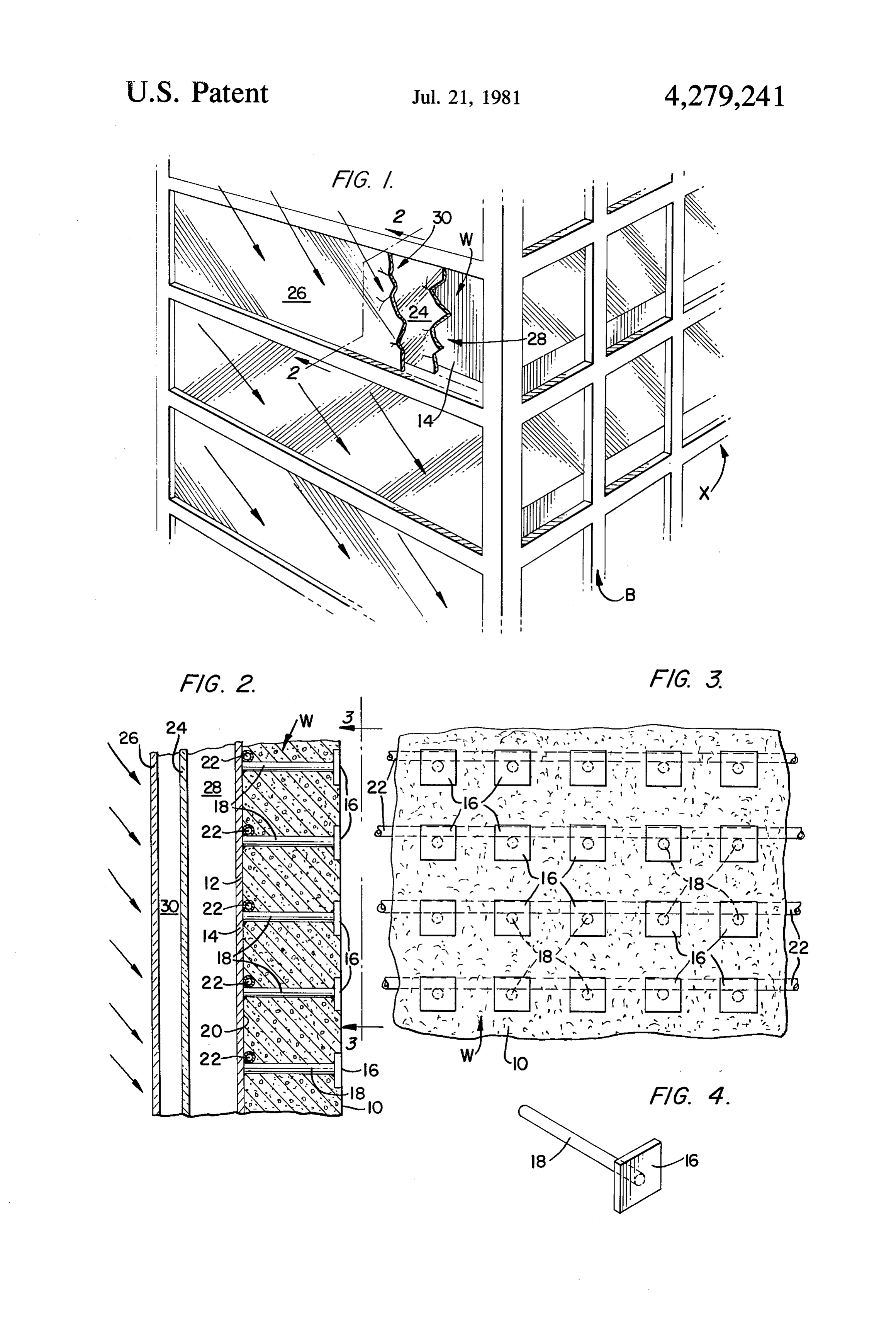
bather or most any school boy with a magnifying glass but also by scientists, engineers, and would-be inventors BRIEF DESCRIPTION OF THE DRAWINGS the world over, particularly in this age of high cost of 20 FIG. 1 represents a view in perspective of a corner of fossil fuels and recognition of our diminishing re a building one side of which incorporates the inventive sources. Efforts of the inventive community are docu concept disclosed herein; mented by the increased number of patents presently granted, yet to date few, if any, of such patents are 25 along FIG. 2 is a sectional view of my invention taken known to be successfully commercialized due to ex the plane 2-2 and looking in the direction of the pected low economic returns attributable to such pa arrows in FIG. 1;
tented devices. FIG. 3 is a view of my invention taken along the Examples of prior art efforts of harnessing solar heat plane 3-3 and looking in the direction of the arrows in energy and converting same to domestic and/or com FIG. 2; and mercial use include, for example, U.S. Pat. Nos. 30 FIG. 4 is a view in perspective of a subassembly of 3,314,414 (Rowekamp); 3,893,506 (Laing); 3,972,317 two essential elements which form part of my invention. (Gallagher); 3,996,919 (Hepp); and 4,015,585 (Fattor). DETAILED DESCRIPTION OF THE Of the prior art listed above, Rowekamp relates to a INVENTION solar collector including an element 31 with an exterior member connected to an interior member by an inter 35 Referring now in detail to the drawings, the reader mediate member extending from the former to the lat should understand that building B includes a plurality of ter. walls W, X, and others not shown. Wall W is repre Laing relates to a device for absorption and emission sented to be located on the side of building B receiving of heat comprising outer sheet metal surface 4 and inner the greatest exposure to the sun and is to be understood sheet metal surface 5 with the latter being disposed to constitute the subject matter for which a patent is against an insulating layer 3 located between the sheet desired. Consideration of FIGS. 2 and 3 along with metal plates and concrete base plate 1. FIG. 1 will readily show that wall W, which has an Gallagher relates to a solar heater for heating fluid inner surface 10 and an outer surface 12, is assembled in passing through a plurality of solar panels disposed in combination with a heat energy absorbing member 14
Hepp relates to a system for collecting and storing disposed outwardly of outer surface 12 for absorbing solar energy comprising panels installed between the solar heatofenergy, heat radiating members 16 disposed joists of a roof whereby the collector surface of each inwardly inner surface 10, and heat transfer elements 18 extending through wall W. Heat transfer elements 18 panel functions as part of the roof of each panel and also are in contact with both heat energy absorbing member includes a heat storage system connected to the back 50 14 and radiating members 16 so that solar heat energy side of each panel.
Fattor relates to a solar heating apparatus comprising absorbed by heat energy absorbing member 14 may be a concrete block 100 having a plurality of water tubes transferred therefrom by heat transfer elements 18 to 102 passing therethrough whereby heat may be trans heat radiating members 16 to heat the interior of build ferred to or from the water and the concrete block 55 ing B. For convenience, heat absorbing member 14 is which functions as a heat storage member. embodied as one continuous relatively large metal plate, although it may take the form of a plurality of smaller
SUMMARY OF THE INVENTION metal plates. Heat radiating members 16, on the other The present invention relates to a new and improved hand, comprise an array of relatively smaller metal structure for converting solar heat energy to usable heat plates, but may be in the form of a single large plate. in domestic, commercial, industrial or like buildings or Heat transfer elements 18 are embodied as a plurality of enclosures. metal rods, bars, or like members. Wall Wis of concrete OBJECTS OF THE INVENTION or like material which will inherently function to store a substantial amount of the heat absorbed by absorbing
Consistent with the summary of the invention set 65 member 14. The heat stored by wall W when the sun is forth above, it is an object of the present invention to shining on heat absorbing member 14 will be given off provide a new and efficient wall structure of such char and returned to the system after the sun sets or other acter as to readily and efficiently convert solar energy wise ceases to shine.
Page 4scan →
As may be clearly seen in FIG. 2, large metal plate 14, acterized in that said heat transfer means is in contact which constitutes the heat absorbing or collector mem with both said heat energy absorbing means and said ber, includes an inner surface 20 disposed in actual or heat radiating means whereby solar heat energy ab substantial abutment against outer surface 12 of wall W. sorbed by said heat absorbing means may be transferred One or more pipes 22 through which water may flow or therefrom by said heat transfer means to said heat radi in which water may be stored are embedded in wall W ating means to heat the interior of said building con adjacent to the inner surface 20 of relatively large metal struction, and said wall is in actual or substantial abut plate 14 and adjacent at least one of the plurality of ment with both said heat energy absorbing means and metal rods, bars, or like members 18 whereby the water said heat radiating means.
in pipes 22 may be heated. Depending upon the amount 10 2. Building construction as defined in claim 1, of water contained in pipes 22 or flowing through pipes wherein one or more pipes through which water may 22, the amount of heat stored or taken out of the system flow are embedded in said wall adjacent to the inner may be controlled. Also, the heated water in pipes 22 surface of said relatively large metal plate and at least may be used for whatever purpose such heated water one of said plurality of metal rods, bars, or like members may be needed. 15 whereby water flowing in said pipes may be heated. Wall W, for example, may be the exterior wall for a 3. Building construction as defined in claim 2, utility room of a home in which one of the pipes 22 may wherein said continuous relatively large metal plate is be tapped so that water heated therein by solar heat may steel and is painted black.
be put to general use. Consistent with conventional 4. Building construction as defined in claim 1, com plumbing practice, pipes 22 may be of copper. With 20 prising in further combination therewith at least two pipes 22 located closely adjacent to inner surface 20 of glass panes extending generally parallel to said continu large metal plate 14, water in pipes 22 can be heated to ous relatively large metal plate and enclosing a first air about 110' F. as pipes 22 themselves or other metal space between one of said glass panes and the outer parts may be heated up to about 130 F. when exposed surface of said continuous relatively large metal plate to direct sunlight for a period of three hours. 25 and enclosing a second air space between said glass As may be seen in FIG. 4, each heat transfer element panes themselves.
18 may be in the form of a solid metal rod assembled, for 5. Building construction having at least one wall with example by being welded, on a metal heat radiating an inner surface and an outer surface comprising in member 16 prior to being installed in combination with combination therewith heat energy absorbing means wall W. When heat transfer elements 18 and heat radiat 30 disposed outwardly of said outer surface for absorbing ing members 16 are installed in wall W, each heat radi solar heat energy, heat radiating means in the form of an ating member 16 is partially embedded in wall W with array of relatively small metal plates disposed inwardly an inner surface being flushed with the inner surface 10 of and abutting said inner surface in flat fashion, and of wall W so as to be exposed to the interior space heat transfer means in the form of a plurality of solid enclosed by wall W to thereby heat such interior space. 35 metal rods, bars, or like rod members without openings The continuously relatively large metal plate 14, for therein extending through said wall, said heat transfer example, may be of steel and is painted black to ensure means being in contact with both said heat energy ab maximum absorptivity and is further combined with sorbing means and said heat radiating means whereby glass panes 24, 26 disposed externally thereof, extending solar heat energy absorbed by said heat energy absorb generally parallel therewith, and enclosing a first air 40 ing means may be transferred therefrom by said heat space 28 between one of the glass panes 24 and the outer transfer means to said heat radiating means to heat the surface of the continuous relatively large metal plate 14 interior of said building construction; wherein said heat and enclosing a second air space 30 between the glass absorbing means comprises at least one continuous rela panes 24, 26 themselves. tively large metal plate; said wall is of concrete or like It will be obvious to those skilled in the art that vari 45 material; said relatively large metal plate includes an ous changes may be made without departing from the inner surface disposed in substantial abutment against scope of the invention and the invention is not to be said outer surface of said wall, and one or more pipes considered limited to what is shown in the drawings and through which water may flow are embedded in said described in the specification. wall adjacent to the inner surface of said relatively large What is claimed is: 50 metal plate and at least one of said plurality of metal 1. Building construction having at least one wall of rods, bars, or like members whereby water flowing in concrete or like material with an inner surface and an said pipes may be heated; said continuous relatively outer surface comprising in combination therewith heat large metal plate is steel and is painted black; said build energy absorbing means in the form of at least one con ing construction having in further combination there tinuous relatively large metal plate disposed outwardly 55 with at least two glass panes extending generally paral of said outer surface for absorbing solar heat energy; lel to said continuous relatively large metal plate and heat radiating means in the form of an array of rela enclosing a first air space between one of said glass tively smaller metal plates disposed inwardly of said panes and the outer surface of said continuous relatively inner surface; and heat transfer means in the form of a large metal plate and enclosing a second air space be plurality of solid metal rods, bars, or like members with tween said glass panes themselves. out openings therein extending through said wall; char k it is sk
Provenance
- Collection
- Patents citing this work
- Pages
- 4
- Method
- pdftotext (the PDF's own text layer) + pdftoppm 300dpi page scans
- Patent office record
- patents.google.com →
- Source
- Google Patents citing-documents table
- Assignee
- Himes John W
- Published
- 1981-07-21
- Transcribed from
- patentimages.storage.googleapis.com →