

patent · US3358732A
Apparatus for valve checking
19 December 1967
Text
Page 1scan →
Filed April 30, 1965
Timing
(no heat req'd)
Demand "d" closed
(heat req'd)
Fre conro fc
Responds
(heat req'd)
Demand "d" o pen
(NO HEAT acao)
(fuel off)
Fre control. fc
Ready for resar
(walwe checker
Restricts fire
CONTRO FC HS E.g.
Wave check comple
Demand "d" closed n. y
Fre control. fc
Responds
Demand "d' open
Fire CONTROL. FC
Ready for restart
v ALVE CHECK COMPLETE
Apparatus for valve checking
Of valve checking means related
To combust on timing
Cam tme unit o to oo represents 2 mn,
Lght off - prepurge
Post
Purge lockout alarm
Opens
Walwe check
Burning
CAM CM OPENS h
Walwe check
Richard w. stuart
Drawings
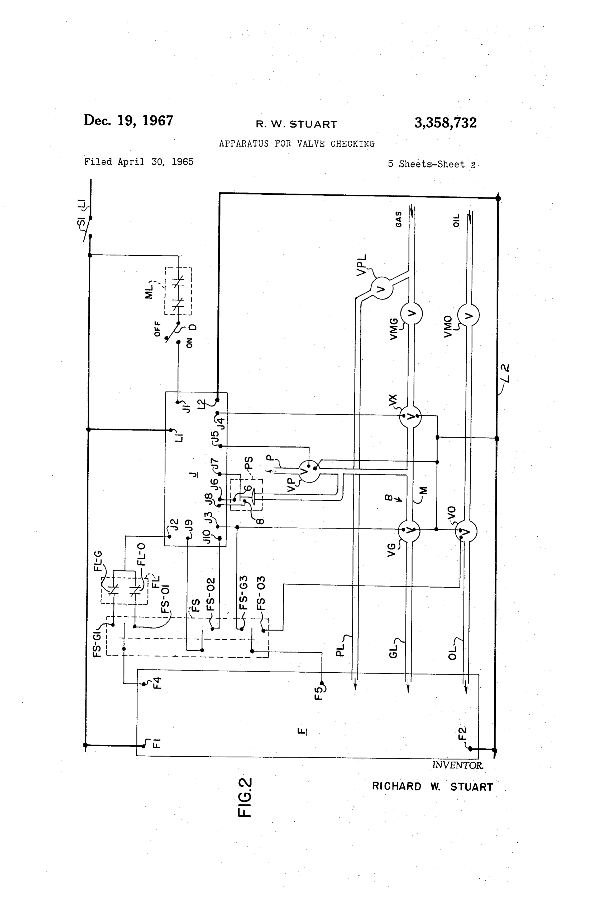
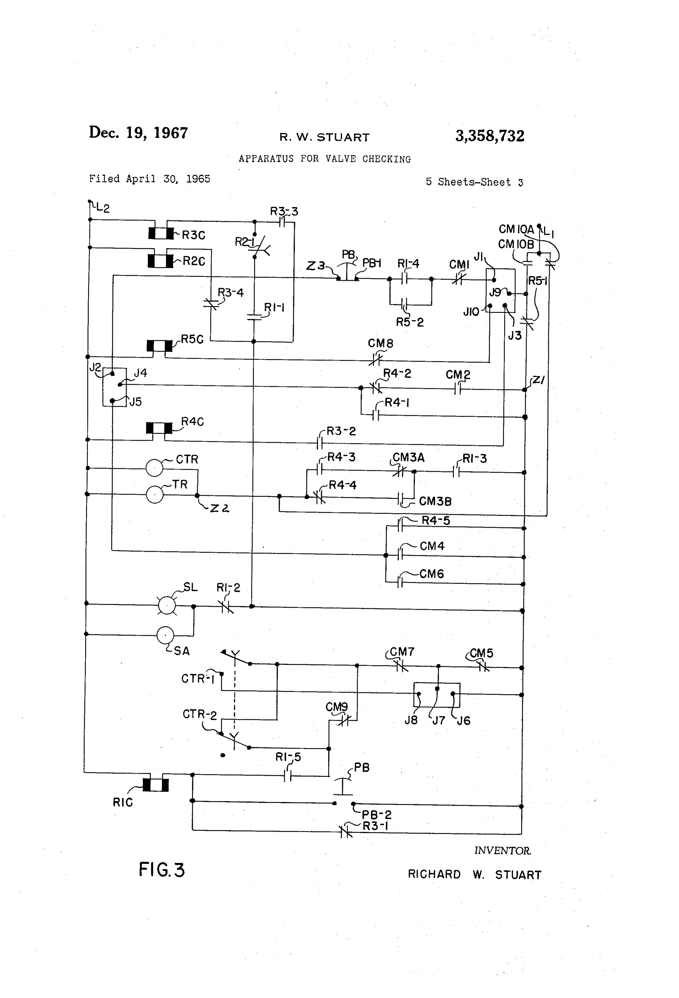
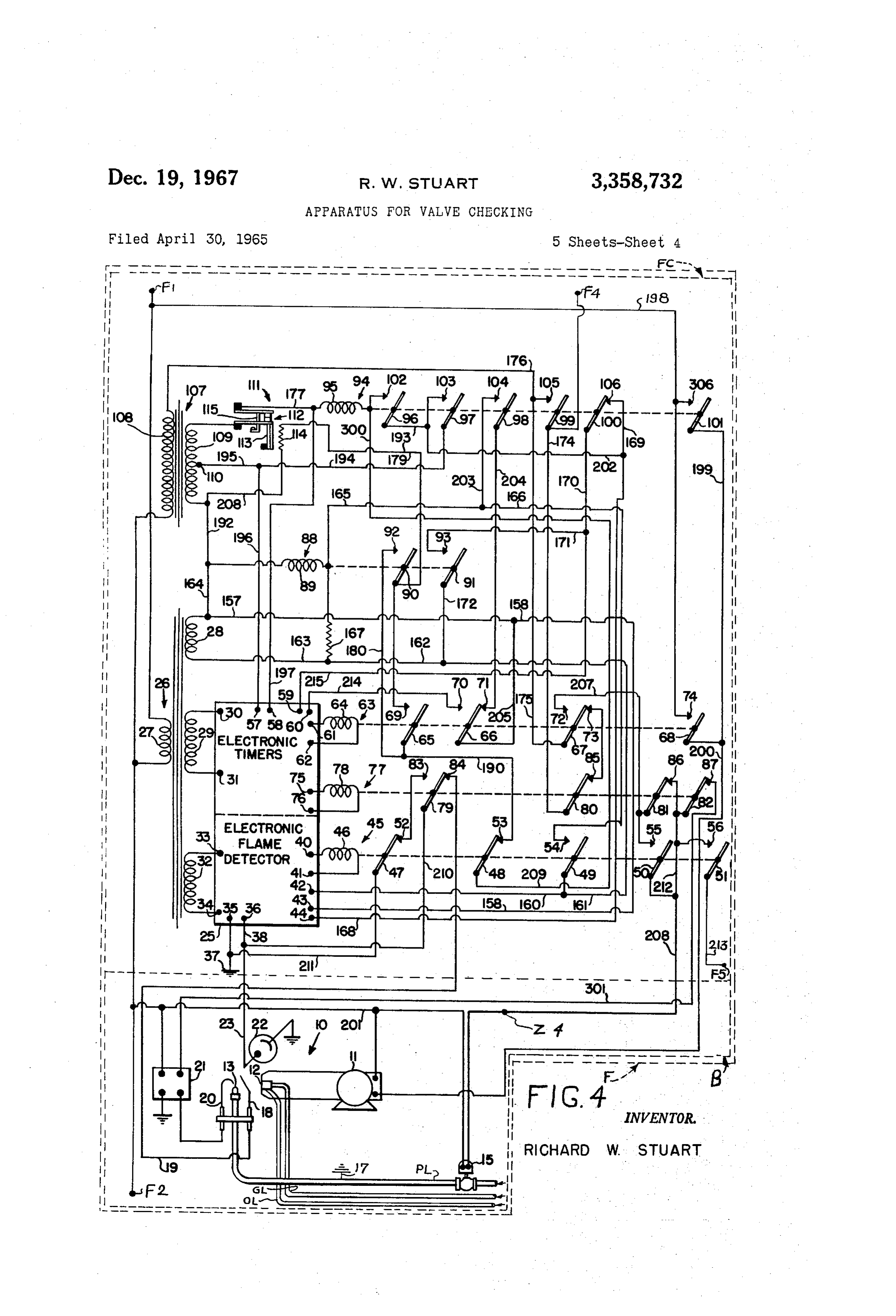
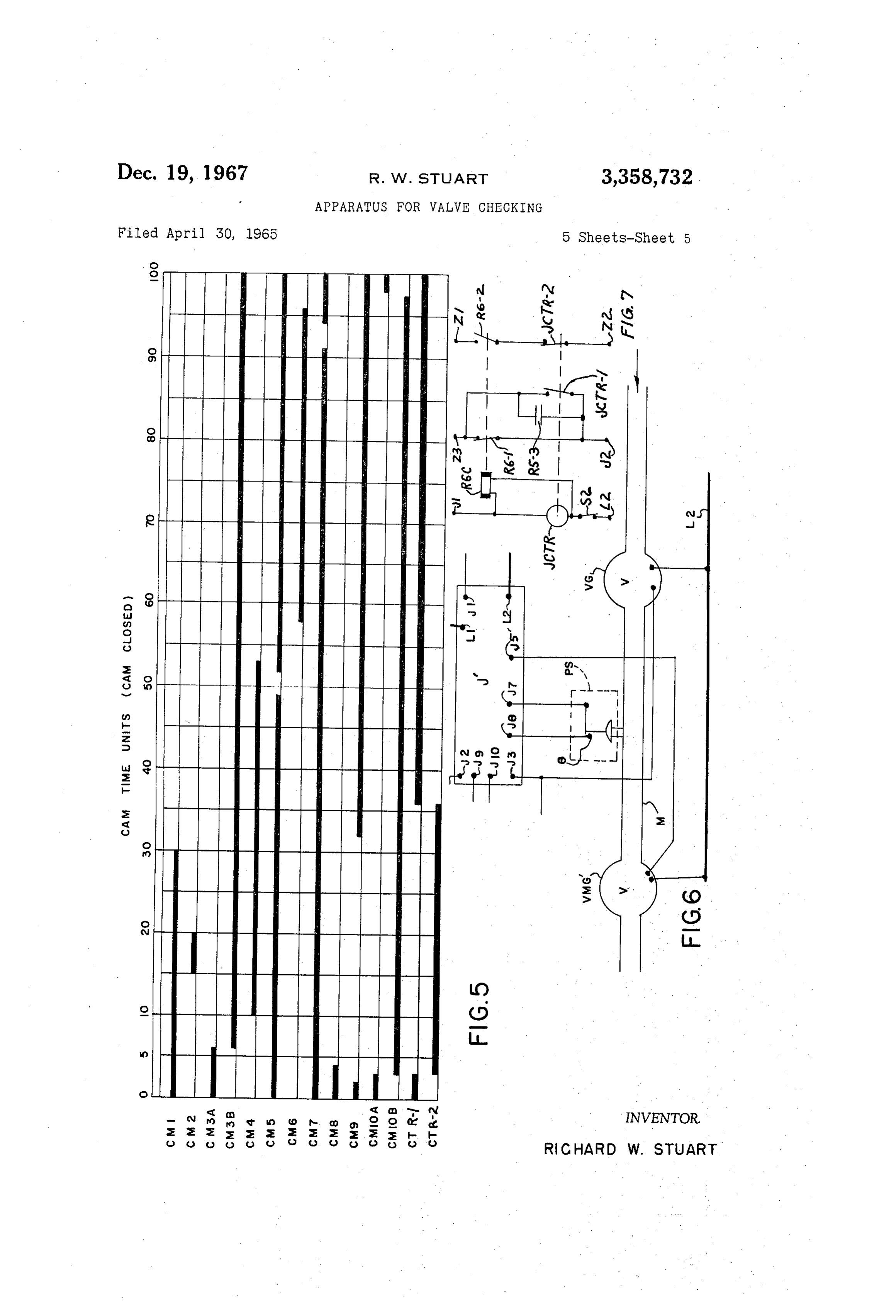
FIG. 6 is a modification adapted to be substituted in of the burner 4 illustrates fire control means FC and a portion FIG. 2 for a portion of the structure therein; and unit B in fire unit F. This FIG. 4 is a slightly modified copy of FIG. 1 from U.S. Patent No.
Page 2drawing sheetscan →
Page 3drawing sheetscan →
Page 4drawing sheetscan →
Page 5drawing sheetscan →
Page 6scan →
United States Patent Office 3,358,732 Patented Dec. 19, 1967
3,358,732 Valve checking means J is usable to check for defects APPARATUS FOR WALWE CHECKING in operation in any fluid controlling valve, such as a Richard W. Stuart, Cleveland, Ohio, assignor to The valve in a water line, brewery flow line, processing flow North American Manufacturing Company, Cleve line, fuel line, etc. The defect detected is generally a land, Ohio, a corporation of Ohio 5 leak in the closed valve but this means J will detect Filed Apr. 30, 1965, Ser. No. 452,100 failures to open and/or close some of the valves. Leak 36 Claims. (CI. 158-11) detection is especially important in fuel lines, where a This invention relates to improvement in an apparatus lines, leak might cause an explosion; and in processing flow for valve checking, and more particularly to means for 0 measurements where a leak would adversely affect accurate batch detecting defective operation or leakage in a valve or required.
valves. Valve checking means J can broadly function in any One of the objects of the present invention is to pro suitable manner by any suitable mechanism, such as hydraulic, mechanical, electrical, and/or electro-mechani vide apparatus for valve checking for detecting, as a cal. Only one form is shown for purposes of illustration defect, a leak in a valve, improper closing and/or open 15 herein.
ing of the valve or valves, leakage, etc.
A further object of the present invention is to provide ly The structure shown in the drawings herein is especial intended for use as part of an apparatus for a boiler a valve checker for checking the operation of any fluid using any conventional fire control means FC in FIG. 4, controlling valve, such as in a water line, brewery line, any conventional burner or combustion unit B in FIGS. processing flow line, fuel line, etc.
A further object of the present invention is to provide 20 2 and 4, and valve checking means J in FIGS. 2 and 3. an apparatus including valve checking means and fire now to structure
This will be broadly explained by reference
FIGS. 2 and 4. The apparatus is capable of op control means combined so that the valve checking means erating checks the operation of the fuel valve controlled by the from theonright fire control means.
either gas or oil as a fuel flowing inwardly toward the left through respectively gas 25 line GL and oil line OL from FIG. 2 to FIG. 4. Flow
A further object of the present invention is to provide is controlled by a valve means including a plurality of Such apparatus wherein all components "fail safe' and valves comprising, gas upstream valve VX in FIG. 2; gas will also "fail safe' upon an electric power failure there downstream valve VG connected to the opposite end of a conduit or manifold M from valve VX to control in
A further object of the present invention is to provide 30 series flow therethrough; gas vent valve VP connected in such apparatus wherein the fire control means is capable fluid communication with conduit or manifold M between of operating on either gas or oil as a fuel and the valve upstream and downstream checking means checks only the gas fuel valve but not tively sealing or venting thisvalves VX and VG for selec conduit for exhaust through the oil fuel valve.
A further object of the present invention is to provide 35 vent port P of vent valve VP; oil valve VO; manually operated main gas line, oil line and pilot line shut off such apparatus wherein the mode of operation of the fire valves VMG, VMO and VPL; and pilot valve 15 in FIG. control means (including any safety cut off device, pre 4. Valve VG is an automatic, safety shut-off valve, and purging means and/or postpurging means therein) and valve of the valve checking means are compatible in operation. safety VX is an automatic, motor-driven, reset valve' or shut-off valve. Valve VP in FIG. 2 is open when
A further object of the present invention is to provide 40 deemergized a valve checking means easily connectible to the exist and VX in and closed when energized; valves VG, VO ing fire control means and readily adaptable to presently when deemergized 2and FIG. and valve 15 in FIG. 4 are closed open when energized; and each designed fire control means.
of these valves is an electrically actuated, solenoid or
A further object of the present invention is to provide motor-driven an apparatus, including a valve checking means, char valve of a conventional type. Vent valve acterized by its inexpensive manufacturing cost, ease of 45 VP is a normally open, fully ported, electrically operated vent valve. Oil valve VO either may be a valve con assembly of its component parts, low operating cost, struc tural simplicity, compactness, strong and sturdy nature, trolling oil flow from a storage head through oil line OL to burner 12 or may be an electrically driven pump, operating efficiency, ease of operation or use, multi plicity of functional advantages for many component 50 since this valve is not checked by valve checking means J. Electrical components are shown in the upper portion parts, operating economy, etc.
These and other objects of the present invention will of FIG. 2. These include miscellaneous limits (boiler become more fully apparent by reference to the appended sure limits) ML; demand switch. D taking the form of a pres claims as the following detailed description proceeds in switch, manually actuatable switch or thermostat reference to the accompanying drawings wherein: actuated switch; and fuel selector switch FS adapted to FIG. 1 is a time diagram showing the timing of the 55 either close simultaneously all selection contacts for one fuel, valve checking means related to combustion timing; oil contacts designated by O or gas contacts desig FIG. 2 is a schematic electrical, fluid flow, etc. layout the nated by G. Contacts FS-G3 and O3, by signal from of the valve checking means J, fire unit F, a portion of fire control unit F, open and close main gas valve burner unit B, and the electrical and other connections 60 at VG or main oil valve VO and provide suitable signal therebetween; terminal J3 to valve checking means J; contacts FS FIG. 3 is an electrical diagram of valve checking has been O2, when closed, tells valve checking means J that oil means J; selected; and contacts FS-O1 and FS-G1 selec FIG. 4 is a diagram of fire unit F, including fire con tively bring into the circuit the fuel sensitive limits FL O for oil or limits FL-G for gas in fuel sensitive limit trol means FC and the remainder of burner unit B; switch FL. This fuel selector switch FS is a three pole, FIG. 5 is a time diagram of the cam closed positions in 65 double throw, center-off switch.
FIG. 6 is a modification adapted to be substituted in of the burner 4 illustrates fire control means FC and a portion FIG. 2 for a portion of the structure therein; and unit B in fire unit F. This FIG. 4 is a slightly modified copy of FIG. 1 from U.S. Patent No.
FIG. 7 is a modification of FIG. 3 permitting change 70 2,751,972, in the phase relationship of the valve checking and com titled "Burner granted June 26, 1956, to J. A. Loeber, and en bustion cycles. Safety Control Apparatus,' suitably modi fied to fit into the present application. A brief compari 7 son of FIG. 4 of the present application with FIG. 1 of D is opened at time “6” to indicate that no more heat is said Loeber patent will reveal that the modification of required, fire control means FC turns off burner 12 to this FIG. 1 has taken place at the bottom, top, upper left discontinue heat, fire control means FC starts a postpurge and lower right of FIG. 1 of said Loeber patent. Elec action, and valve checking begins; (4) from time "6' to trical lines and reference numerals 173 and 213 have been '98,' valve checking occurs by valve checking means J, respectively completely and partially deleted from FIG. 1. and fire control means FC is restricted from restarting Ground 17 has been relocated for convenience. The pres during this period but gets ready for a restart; and (5) ent application has the following component parts corre then the valve checking means J rapidly travels from sponding with those in FIG. 1: terminal F2 and line L2 time "98" back to time '3” to await the next closing in present FIGS. 4 and 2 with line 155 in FIG. 1 of said O of demand switch D at time “3." The rest of this descrip patent; terminal F1 and line L1 in FIGS. 4 and 2 with of tion will be directed to a detailed explanation of this mode line 156; miscellaneous limits ML in F.G. 2 with limit operation.
control. 116; demand switch D in FIG. 2 of the present ap FIGS. 2, 3 and 4 show the system at rest with all com plication with switch 117; master switch S1 in FIG. 2 ponents shown as being deenergized with power off. All with the master switch in Loeber; gas valve VG with gas 5 circuits are depowered and no demand for heat is occur valve 14. Since the mode of operation of FIG. 4 is sub ring. Cam contacts CM1, CM2, CM3A, CM3B, CM4, stantially the same as that in the Loeber patent, the Loeber CM5, CM6, CM7, CM8, CM9, CM10A and CM10B are actuated by synchronously driven cams driven by an patent is being incorporated herein by reference thereto, electric motor in cam timer TR and are shown at their and there will be frequent references hereafter to por tions in the Loeber patent whenever they apply. 20 time “0” or normal position; and check timer contacts However, it will be readily apparent hereinafter that CTR- and CTR-2 are actuated by check timer CTR and are shown in their unactuated position occupied from valve checking means J may be used with any suitable fire control means or burner unit and is not restricted time '3' to "36." Relay coils R1C, R2C, R3C, R4C and to the disclosure in the Loeber patent. Loeber has been R5C in FIG. 2 respectively control and actuate the relay used only for purposes of illustration since it illustrates 25 contacts having the same first two reference numeras. a fairly complete, typical, more complex fire control and For example, relay coil R1C actuates relay contacts burner unit. It should be understood that it is possible to R1-1, R1-2, etc. Also, push buttons PB in FIG. 2 are use only one or only some of the illustrated features of a single push button PB rigidly connecting and carrying the Loeber patent, if you want to do so. It is not neces push button contacts PB-1 and PB-2. sary to use all of the features therein. Valve checking 30 eralBefore starting the description, these additional gen comments can be made. Cams CM10A and CM10B means J is usable with the simplest as well as the most simulate a power failure to reestablish the original cir complex fire control means because the complete mode of operation of valve checking means J is controlled by cuits and to reset them to their original condition in valve the signals from the fire control means FC opening and checking means J. Also, relay coil R1C is not latched closing main gas valve VG. 35 in but is electrically connected to provide a true failure Miscellaneous limits ML and fuel sensitive limits FL system. It is a cocked trigger ready to shut down the ap in FIG. 2 are conventional burner controls. Miscellaneous paratus and to give a suitable alarm, either audible or limits ML are limits required to safely burn both fuels, visual.
oil and gas; and may include boiler or furnace pressure, with The description will start with the apparatus at rest, temperature and water level to actuate the limits. Fuel 40 no heat demand, but with the set up of the starting Sensitive limits FL has limits peculiar to the different fuels circuits to provide power to not only valve checking burned-gas pressure and ambient temperature may actu means J but also fire control means FC. ate the gas limits; oil pressure, oil temperature and atomiz Power is supplied to valve checking means J in FIGS. 2 ing air pressure may actuate the oil limits. and 3 at time "0." Closing main switch S1 energizes cam FIGS. 2 and 4 include some components that will be 45 timer TR and check timer CTR by forming CIRCUIT frequently mentioned hereinafter. They have a fuel burner tact NO. C1 from line L1 in FIGS. 2 and 3 through cam con 12, fuel supply conduits GL and OL supplying gas fuel checkCM10A in FIG. 3 now closed, cam timer TR and timer CTR in parallel, and line T2 in FIGS 3 and oil fuel to burner 12, gas control valve VG and oil and 2.
control valve VO as burner valves controlling fuel flow At time "3," numerous circuits are formed and broken. through these conduits to the burner for operating the At time "3," opening cam contact CM10A then breaks burner through a burning cycle, fire control means FC for controlling the operation of burner 12 by valves VG CIRCUIT NO. C1 to deenergize cam time TR and check and VO, and blower 11 causing a prepurge and a post timer CTR. This deemergizing action causes check timer CTR contacts CTR-1 and CTR-2 to reset and to assume purge in the burning zone of burner 12. Valve checking means J is shown in more detail in FIGS. 3, 5 and 6. 55 the position shown in FIGS. 3 and 5 if they had been in the opposite position (see FIG. 5) from the preceding
This valve checking means is operable to detect the de fect in the operation of gas valves VG, VX, and VP valve checking cycle. However, this is a 30 unit check while the valves are in their flow controlling position timer-from time "3" to “6,' it will make a false start, and at time "6,” it will begin to properly time out its 30 shown in FIG. 2. It is not necessary to disassemble any valve from the flow line to check its mode of operation. 60 time units, as will be brought out in more detail herein FIG. 1 shows the time relationship between valve after. At time "3," closing cam contact CM10B performs checking and combustion through two cycles of each to present a good introduction to the operation of the dis Several operations, including: (1) momentarily energizing closed apparatus. The description is made with respect to failure signal light SL to cause it to flick on now to show "100' cam timer time units (the time for valve checking 85 that it is operating properly by forming CIRCUIT NO. C3 means J) representing two minutes of time, as an exam from line L1 in FIG. 3 through cam contact CM10B ple, but it should be readily apparent that any suitable normally open but now closed at time “3, normally time can be used. This sequence occurs: (1) From time closed relay contact R5-1 of relay coil R5C, normally "0'-'3” (timer time units of valve checking means J), closed relay contact R1-2 of oil relay coil RIC, failure both valve checking means J and fire control means FC 70 visual signal lamp SL and audible signal alarm SA, and are at rest; (2) after demand switch. D is closed at time line L2; (2) energizing system failure relay coil R1C by "3' to indicate that heat is required, fire control means forming CIRCUIT NO. C5 from line L1 in FIG. 3 through FC responds, fuel is burnt at burner 12 in FIG. 4 to pro normally open cam contact CM10B closed at time “3, wide the requested heat, and valve checking means J normally closed relay contact R5-1 of relay coil R5C, moves from time "3' to “6”; (3) when demand switch 75 normally closed relay contact R3-1 of relay coil R3C, 8 system failure relay coil R1C, and line L2; and (3) occurs. Now, fire control means FC in FIG. 4 gives an energizing delay coil R2C by forming CIRCUIT NO. electrical signal at terminal F5 in FIGS. 4 and 2 to gas C7 from L1 in FIG. 3 through cam contact CM10B valve VG and at terminal J3 of valve checking means J normally open but now closed at time "3," normally in FIG. 2 when fuel selecter switch FS is in the gas selec closed relay contact R5-1 of relay coil R5C, normally tion position with contact FS-G3 closed. Fire control closed relay contact R3-4 of relay coil R3C, delay relay means FC in FIG. 4 provides this signal after flame is coil R2C and line L2. Energizing system failure relay proven at flame electrode 18 in FIG. 4. Then, upstream coil R1C: (1) opens normally closed relay contact R1-2 and downstream gas valves VX and VG are opened and of relay coil RC to break Circuit No. C3 to deenergize vent valve VP is closed. The following paragraphs will and turn off failure signal lamp SL and signal alarm SA; O describe this mode of operation in more detail. and (2) closes normally open relay contact R1-5 of Now, Circuit No. C19 is formed to tell the fire control relay coil R1C to hold energized system failure relay coil means FC that it may operate. Closing demand switch R1C by forming HOLDING CIRCUIT C11 from Line D in FIG. 2 energizes primary transformer coil 108 in L1 in FIG. 3 through cam contact CM10B normally open but now closed at time "3," normally closed relay contact 5 FIG. 4 by forming CIRCUIT NO. C19 from line L1 in FIG. 2 through miscellaneous limits ML; normally open
R5-1 of relay coil R5C, cam contacts CM5 and CM7 demand Switch. D now closed; terminal J1 in FIGS. 2 and now closed, check timer contact CTR-2 closed at time 3; closed cam contact CM1, normally open relay contact '3” after Circuit No. C was broken, normally open relay R1-4 of relay coil R1C now closed by energized relay contact R1-5 of relay coil R1C now closed by energized coil RiC; normally closed push button PB contact PB-1; relay coil R1C, system failure relay coil R1C, and line L2. 20 terminal J2 in FIGS. 3 and 2; gas fuel sensitive limit After two seconds time delay, delay relay coil R2C closed contact FL-G in fuel sensitive limit switch FL in closes the time delay relay contact R2-1 of relay coil FIG. 2; closed contact FS-G1 in fuel selector switch FS; R2C and energizes system rest relay coil R3C by forming terminal F4 in FIGS. 2 and 4; line 174 in FIG. 4; nor CIRCUIT NO. C13 from line L1 in FIG. 3 through nor mally closed relay contact 80, 85 of relay coil 78; nor mally open cam contact CM10B now closed after time 25 mally closed relay contact 73, 67 of relay coil 64; line "3," normally closed relay contact R5-1 of relay coil 175; line i76; transformer primary coil 108; terminal F2 R5C, normally open relay contact R1-1 of relay coil R1C in FIGS. 4 and 2; and line L2 in FIG. 2. This Circuit No. now closed by energized relay coil R1C, normally open C19 is formed in place of the circuit formed by closing time delay relay contact R2-1 of relay coil R2C now switch 117 in said Loeber patent and so described in lines closed by energized relay coil R2C, system reset relay 30 20-32, column 7, of said Loeber patent. coil R3C, and line L2. This time delay gives relay contact Fire control means FC operates substantially as de R1-5 of relay coil R1C enough time to stop bouncing Scribed in line 39, column 7, to line 11, column 10, of said and stay closed to firmly form Circuit Nos. C5 and C1 Loeber patent with the difference that now, because of before relay coil R3C is energized. If this time delay were the alteration made in present drawing FIG. 4 to FIG. 1 not provided, it might sometimes be necessary, if relay 35 of that patent: (1) the circuits described in line 7-12, contact R1-5 of relay coil RiC were not closed, to push column 8; lines 25-27, column 9; lines 39-49, column 9; button PB to close its contact PB-2 to maintain system and line 73, column 9, to line 11, column 10, of said failure relay coil RiC energized after Circuit No. C5 is Loeber patent go through line 198 in FIG. 4, terminal broken hereafter. Energizing system reset relay coil R3C:
(1) opens normally closed relay contact R3-1 to break 40 linesin198,
F1 FIGS. 4 and 2, and line L1 in FIG. 2 instead of 173 and 156 in FIG. 1 of said Loeber patent;
Circuit No. C5 but system failure relay coil R1C is still held energized by Circuit No. C11; (2) closes normally go through terminal F2 in FIGS. 4 and 2 and line L2 in FIG. 2 instead of through line 155 in FIG. 1 of said open relay contact R3-3 to hold energized system reset relay coil R3C by forming HOLDING CIRCUIT NO. 4 and 2patent; Loeber and the and/or go through terminal F4 in FIGS.
reverse direction along Circuit No. C19.
C15 along the same path as Circuit No. C13 but through 45 to line L1 in FIG. 2 instead of through parts 117, 116, normally open relay contact R3-3 of relay coil R3C now 173 and 156 in FIG. 1 of said Loeber patent; and (2) the closed by energized relay coil R3C instead of through circuit described in lines relay contacts R1-1 and R2-1 of relay coils RC and 36, column 9, follow the68-71, column 7, and lines 34 path of Circuit No. C19 but
R2C; and (3) opens normally open relay contact R3-4 goes through closed contact of relay coil R3C to break Circuit No. C7 and deemergize 50 contacts 67, 73 and 80, 85. 99, 105 instead of closed delay relay coil R2C. Deenergized delay relay coil R2C Now, fire control means FC gives a signal at its ter opens its relay contact R2-1 to break Circuit No. C13 but system reset relay coil R3C is held energized by Cir and to F5terminal minal in FIGS. 2 and 4 to gas valve VG in FIG. 2
J3 in FIG. 2 after the flame has been cuit No. C15.
Closing main switch S1 in FIG. 2 also energizes fire 55 68-70, column 9; andelectrode proven at pilot flame 18 in FIG. 4. See lines control means FC in FIG. 4 to standby condition. The op Loeber patent explaining how flame atcolumn electrode 18 ener erations now occurring are described in said Loeber pat gizes relay coil 46. It will be apparent hereafter ent from line 5, column 6, to line 19, column 7. The only valve checking means J includes means responsive tothat the difference is in lines 5-8, column 6, of said Loeber patent. demand for fuel by the signal from fire control means FC Instead of this description, closing main switch S1 in the for readying valve checking means J for its valve check present application FIG. 2 energizes primary coil 27 in 60 ing cycle and for opening upstream valve VX and for FIG. 4 by forming CIRCUIT NO. C17 from line L1 in closing vent valve VP with the demand for fuel by fire FIG. 2 through fire unit terminal F1 in FIGS. 2 and 4, primary transformer winding 27 in FIG. 4, fire unit ter control means FC opening downstream valve VG. Fire control means FC gives this signal at terminal F5 minal F2 in FIGS. 4 and 2, and line L2 in FIG. 2. 65 by forming CIRCUIT NO. C21 (instead of the circuit It should be understood that FIG. 2 of said Loeber pat described ent is incorporated in this disclosure by a reference when line L1 ininFIG. lines 12-23, column 10, of said patent) from 2 along the same path as Circuit No.
ever the electronic timers or electronic flame detector in C19 to terminal F4 in FIG. 4 and then through normally present FIG. 4 is described therein. open relay contact 99, 105 of relay coil 95 now closed Now, GAS CAMBUSTION CYCLE GCC occurs, and 70 by is described hereafter. energized relay coil 95; line 175; normally open relay When demand switch. D in FIG. 2 is closed (such as relay coil67,64;72 line contact of relay coil 64 now closed by energized by a Suitable thermostat, manually or by a pressure de 50 and contact 56, 207; normally open relay contact 55, 51 of relay coil 46 via line 212 now vice responsive to the heat needs of the boiler), burner 12 closed by energized relay coil 46; line 213; terminal F5 in FIG. 4 provides the heat demanded and gas combustion 75 in FIGS. 4 and 2; closed fuel selector switch contact
Page 9scan →
7 will be apparent that valve checking means J includes
FS-G3 in FIG. 2; through parallel circuits to line L2: means responsive to shut-off of fuel to burner 12, by the (1) through gas fuel valve VG and (2) through ter stopping of this signal to close downstream valve VG, by minal J3 in FIGS. 2 and 3, normally open relay contact
R3-2 of relay coil R3C now closed by energized relay fire control means FC for starting the valve checking coil R3C, and fuel slave relay coil R4C. This action of cycle by valve checking means J and for closing upstream forming Circuit No. C21 thus energizes fuel slave relay valve VX and opening vent valve VP at the terminal end coil R4C and energizes and opens gas valve VG by this of the burning cycle and at the start of the valve check signal transmitted from terminal F5. ing cycle. Combustion may be stopped by any of various Energizing fuel slave relay coil R4C: (1) closes its events, such as: (1) the heat need is satisfied and de relay contact R4-3 to energize cam timer TR and check 0 47-49,mand switch. D in FIG. 2 is opened, as described in lines timer CTR by forming CIRCUIT NO. C23 from line L1 column 11, of said Loeber patent by opening de in FIG. 3 through normally open cam contact CM10B mand switch 117 and deemergizing main relay control now closed at time “3,' normally closed relay contact coil 95; (2) the flame at burner 12 in FIG. 4 goes out, as R5-1 of relay coil R5C, normally open relay contact described in lines 15-18, column 11, of said patent by de R1-3 of relay coi R1C now closed by energized relay 5 energizing coil 46 of relay 45; or (3) the gas pressure is coil R1C, closed cam contact CM3A, normally open too low.
relay contact R4-3 of relay coii R4C now closed by The safest procedure requires that the system be re energized coil R4C, cam timer TR and check timer CTR turned to its “off” position at the end of the combustion in parallel, and line L2; (2) closes its relay contact R4-1 period by closing both main gas valves VX and VG and to energize and open upstream valve VX by forming 20 opening vent valve VP before starting the valve check by CIRCUIT NO. C25 from line L1 in FIG. 3 through closing the vent valve VP, and this procedure automati normally open cam contact CM10B closed at time “3,” cally occurs here. While postpurging of the burning zone normally closed relay contact R5-1 of relay coil R5C, of burner 12 occurs, as described in lines 51-60, column normally open relay contact R4-1 of relay coil R4C 11, of said Loeber patent, the beginning portion of check now closed by energized relay coil R4C, terminal J4 in 25 ing cycle is also occurring during this postpurging opera FIGS. 3 and 2, upstream valve VX in FIG. 2, and line tion. Circuit No. C21 is broken to deemergize fuel slave L2; and (3) closes its relay contact R4-5 to energize and relay coil R4C and to deenergize and close downstream close vent valve VP by forming CIRCUIT NO. C27 from gas valve VG when fire control means FC no longer emits line L1 in FIG. 3 through normally open cam contact its signal from terminal F5 because: (1) demand switch CM10B now closed at time "3," normally closed relay 30 D in FIG. 2 is opened to deemergize relay coil 95 in FIG. contact R5-1 of relay coil R5C, normally open relay con 4 to open its normally open relay contact 99, 105, as de tact R4-5 of relay coil R4C now closed by energized relay scribed in line 49, column 11, of said Loeber patent; or coil R4C, terminal J5 in FIGS. 3 and 2, vent valve VP (2) the flame has gone out to deemergize relay 45 coil 46 in FIG. 2, and line L2. Forming Circuit No. C23 causes 35 in FIG. 4 and open its normally open relay contacts 51, check timer CTR to begin to time but this is a false start, 56 and 50, 55 as described in line 18, column 11, of said and the true timing action will begin at time "6,' as Loeber patent. This ends GAS COMBUSTION CYCLE will be brought out in more detail hereinafter. GCC.
Now, an indefinite period of burning or combustion Deenergizing fuel slave relay coil R4C: (1) opens its occurs, as shown by the dotted line in FIG. 1. The time 40 normally open relay contact R4-1 to break Circuit No. length is solely determined by the length of time that C25 to deemergize and close upstream valve VX; and (2) demand switch D is closed. The action now occurring is opens its normally open relay contact R4-5 to break Cir described in line 25, column 10, to line 10, column 11, cuit No. C27 to deemergize and open went valve VP. of said Loeber patent. This combustion occurs for an At time "6,” cam contact CM3B is closed and normally indefinite time period until heat demand is satisfied. closed contact R4-4 is now closed by deemergized relay The cam timer TR and check timer CTR remain at 45 coil R4C to energize cam timer TR and check timer CTR time “6” during this combustion operation, as shown by by forming CIRCUIT NO. C29 from line L1 in F.G. 3 FIG. 1. This is true because cam contact CM3A opens through cam contact CM10B now closed, normally closed at time “6” to break Circuit No. C23 to deemergize cam relay contact R5-1 of relay coil RSC, normally open timer TR and check timer CTR and thus reset the check Telay contact R1-3 of relay coil R1C closed by energized timer to start it timing again when it is subsequently 50 relay coil R1C, cam contact CM3B closed at time “6, energized. normally closed relay contact R4-4 of relay coil R4C, If combustion had gone off between time '3' and cam timer TR and check timer CTR in parallel, and line time "6,' only a valve checking cycle is missed. Then, L2. Now, check timer CTR makes a "true" start and starts cam contact CM3A is closed and fuel slave relay coil to time its 30 time units before flipping over to its other R4C is energized by Circuit No. C21, while flame occurs, 55 position at time “36.” to energize cam timer TR by Circuit No. C23. Cam con At time “10,” cam contact CM4 closes to energize and tact CM3A is closed to indicate the rest (time "O' to "3') close vent valve VP by forming CIRCUIT NO. C31 from and burning position, and cam contact CM3B is other line L2 in FIG. 3 through cam contact CM10B now wise closed to indicate the remaining or non-burning closed, normally closed relay contact R5-1 of relay coil position. If combustion goes out, fire control means FC 60 R5C, relay coil R5C, cam contact CM4 closed at time stops emitting a signal at terminal F5 for any of the "10,' terminal J5 in FIGS. 3 and 2, vent valve VP in reasons given in the next paragraph and fuel slave relay FIG. 2, and Line L2.
coil R4C is deemergized to open its normally open relay The first valve check starts and control is transferred contact R4-3 in the cam contact CM3A closed position from fire control means FC to valve checking means J. so valve checking means J can not get to the cam con 65 Now it will be apparent that valve checking means J. tact CM3B closed position at time “6,' and valve check includes means for sequentially opening upstream valve ing means J stays in this position until the next valve WX to admit fluid under pressure to conduit or manifold checking cycle is reached. However, fire control means M while downstream valve VG and vent valve VP are FC can restart because Circuit No. C1 energizes System closed to pressurize conduit M, closing upstream valve failure relay coil RiC to close its normally open con 70 VX, and taking pressure readings on conduit M over a tact R.1-4 to form Circuit No. C19 so that an intervening time interval to detect any leak in said downstream valve burning cycle can occur. VG and/or vent valve VP by drop in this pressure. If combustion stops, the signal provided by fire con At time “15,' cam contact CM2 closes to energize and trol means FC at terminal F5 is stopped so that no signal open upstream valve VX to fill manifold M with line gas is provided to terminal J3 and to valve WG in FIG. 2. It 75 pressure by forming CIRCUIT NO. C33 from line L1 in
Page 10scan →
FIG. 3 through cam contact CM10B now closed, normally forming CIRCUIT NO. C37 from line L1 in FIG. 3 closed relay contact R5-1 of relay coil R5C, cam contact through cam contact CM10B now closed, normally closed CM2 closed at time "15,' normally closed relay contact relay contact R5-1 of relay coil R5C, normally open but R4-2 of relay coil R4C, terminal J4 in FIGS. 3 and 2, now closed push button contact PB-2, system failure re upstream valve VX in FIG 2, and line L2. lay coil R1C, and line L2. Simultaneously opening push At time "20,' cam contact CM2 opens to deemergize button contact PB-1 breaks Circuit No. C19 to deemer and close upstream valve VX by breaking Circuit No. gize fire control means FC in the same manner as open C33. Now, line gas pressure is trapped in manifold M. ing demand switch. D. Push button PB must be pushed Control is transferred from fire control means FC to valve checking means J at time "30.' Then, cam contact 10 is heretheshown until appropriate open cam contact recloses, which as open cam contact CM5. Hence, valve
CM1 opens to break Circuit No. C19 to deemergize fire checking means J includes a manually actuatable, by control means FC by deemergizing transformer 108. Then, pass means in push button PB for selectively by-passing even if demand switch. D in FIG. 2 closes, fire control this safety means or alarm to continue operation of means FC cannot relight burner 12. valve checking means J at the will of the operator if a Check timer CTR is actuated at time “36' since it is 5 defect in any of the valves is detected. constructed to flip its contacts (open contact CTR-2 and This is merely one form of alarm, lock out and by close contact CTR-1) after timing 30 time units and the pass system. The specific one designed for any specific timing thereof began at time "6.” However, before that job will be determined by the factors involved by balanc happens, cam contact CM9 closes at time “32” to hold system failure relay coil R1C energized by forming 20 ing sure safety against utility. Some operators want to be that maximum safety is obtained. Then, complete
HOLDING CIRCUIT NO. C34 from line L1 in FIG. 3 lock out with no means to by-pass might be desired; through cam contact CM10B now closed; normally closed this can be obtained by eliminating push button contact relay contact R5-1 of relay coil R5C; cam contacts CM5, PB-2. For example, this might be true in a public utility, CM7 and CM9 now closed; normally open relay contact such as a telephone company, wanting to be sure that no R1-5 of relay coil R1C closed by relay coil R1C; system 25 explosion would occur, if it had adequate standby boiler failure relay coil R1C; and line L2. Now, when check facilities to take over the heat needs until this boiler timer CTR flips to its actuated position at time "36' to was repaired. In other installations, utility might be more open its contact CTR-2 to break Circuit No. C11, Circuit important than maximum safety. Then, the operator No. C34 holds system failure relay coil R1C energized. may want only a warning that he could readily by-pass After manifold M has been pressurized from time “15” 30 because it was absolutely essential that his sole boiler to time "49,” pressure readings are taken of the pressure remain in operation. An example of such installation in manifold M from time “49” to time “52” If the pres would be a greenhouse. Hence, the type of alarm, lock Sure holds, contact 6 of pressure switch PS in FIG. 2 stays closed. Then, closed contact 6 holds energized sys out, and by-pass has an infinite number of combinations depending upon the desires of the operator. The alarm tem failure relay coil R1C by forming HOLDING CIR 35 may only warn him and do nothing to the system; may CUIT NO. C35 along the same path as Circuit No. C34 lock him out with by-pass contact PB-2 available; may except through terminal J6 in FIGS. 3 and 2, closed con lock him out immediately with no possibility of by tact 6 of pressure switch PS and terminal J7 in FIGS. 2 passing the lock out; or may lock him out after the first and 3 instead of cam contact CM5. At time “49, cam warning, any suitable combination of warnings, the end contact CMS opens to break Circuit No. C34. If the pres 40 of the valve checking cycle, the beginning of the combus Sure holds at the proper value to keep pressure switch PS tion cycle, etc.
contact 6 closed, this first valve check is successful. This is the end of the description of ALARM SE If pressure does not hold and failure occurs, pressure QUENCE AS.
Switch PS contact 6 does not stay closed and system failure At time “52,' the pressure reading of the first valve relay coil R1C is deenergized as opening pressure switch 45 check on manifold M ends. Then, cam contact CM5 re PS contact 6 breaks Circuit No. C35. closes to reform Circuit No. C34 to form a holding cir Deenergizing system failure relay coil R1C starts cuit energizing system failure relay coil R1C. ALARM SEQUENCE AS described hereafter. Then, the first valve check ends. This Alarm Sequence AS is a safety means prevent The second valve check now starts. Now, it will be ing continued operation of valve checking means J if a 50 apparent that valve checking means J includes means defect in operation of one or more of these valves is for sequentially opening vent valve VP while upstream thus detected. Now, deenergized safety failure relay coil valve VX and downstream valve VG are closed so as RiC: (1) closes its normally closed relay contact R1-2 to get "0" pressure in conduit M, closing vent valve VP, to reform Circuit No. C3 to reenergize failure visual and checking if the pressure in conduit M rises over a signal lamp SL and audible signal alarm SA; (2) opens 55 its normally open relay contact R1-3 to break Circuit time interval to detect any leak in upstream valve VX. Vent valve VP is deenergized and opened to get “0”
No. C29 to deenergize, lock out, and stop cam timer pressure in manifold M. At time '53,’ cam contact TR and check timer CTR; and (3) opensits normally CM4 opens to break Circuit No. C31 to deemergize and open relay contact R1-4 to break Circuit No. C19 to open vent valve VP. The pressure drop in manifold M deenergize and lock out fire control means FC (which 60 opens pressure switch PS contact 6 to break Circuit No. does not need to be deenergized here, but will be de energized, if necessary). This action shuts down the whole C35 but system failure relay coil R1C is held energized by Circuit No. C34.
apparatus by stopping valve checking means J and fire At time "58,” vent valve VP is energized and closed. control means FC.
Then, cam contact CM6 closes to energize and close
If one desires to continue this valve checking cycle, 65 vent valve this alarm can be by-passed by pressing push button same path VP as by forming CIRCUIT NO. C39 along the
Circuit No. C31 but through cam contact
PB. This single push button PB has two interlocked and CM6 now closed at time "58" instead of through cam rigidly connected contacts PB-1 and PB-2 even though contact CM4.
two push buttons PB are shown in FIG. 3. Thus pushing Now, the valve check is made with "0" pressure in push button PB also keeps fire control means FC de- 70 manifold energized, if necessary. These interlocked contacts on contact 8 M. If “0” pressure holds, pressure switch PS remains closed. This low pressure closing pres push button PB prevent the operator from jamming push Sure switch PS contact 8 holds energized system failure button PB in an unsafe position with some instrument, relay coil R1C by forming HOLDING CIRCUIT NO. such as a toothpick. Closing contact PB-2 reenergizes C41 from line L1 in FIG. 3 through cam contact CM10B system failure relay coil R1C to override the alarm by 75 now closed, normally closed relay contact R5-1 of re 11 lay coil R5C, closed cam contact CM5, terminal J7 in ent as being within the scope of the present invention by FIGS. 3 and 2, pressure switch PS contact 8 closed by consideration of the examples in the next two paragraphs. the “0” pressure, terminal J8 in FIGS. 2 and 3, check First, two of the FIG. 6 structures may be used. Then, timer contact CTR-1 closed after check timer CTR was each valve VPL and VO may be separately checked by actuated or flipped after time "36,” closed cam contact adding thereto from FIG. 6 the wiring to valve VG, modi CM9, normally open relay contact R1-5 of relay coil fied valve checking means J, manually or automatically R1C now closed by energized relay coil R1C, system closeable valve VMG' downstream therefrom respec failure relay coil R1C, and line L2. At time "91,” cam tively in each fuel line PL and OL, pressure switch PS and contact CM7 opens to break Circuit No. C34 but if the its contact 8, and the wiring therebetween. Then, each low pressure holds to keep pressure switch PS contact O valve VPL and VO can be checked by a duplicate of the 8 closed, system failure relay coil R1C is held closed by construction shown in FIG. 6. However, valve checking Circuit No. C41. means J and valve VPL is connected to fire control means If the pressure does not hold and failure occurs, pres FC at terminal Z4 in FIG. 4 instead of terminal F5 in sure switch PS contact 8 does not stay closed. Opening FIGS. 2 and 4, so valve checking means J is responsive pressure switch PS contact 8 breaks Circuit No. C41 15 to closing of pilot valve 15 (controlled by the circuits to deemergize system failure relay coil R1C to start described in lines 39-49, column 9 and line 73, column 9, Alarm Sequence AS to occur to energize failure signal to line 11, column 10, of said Loeber patent) instead of lamp SL and to lock out and stop the valve checking can main gas valve VG. Also, cam contact CM1 in FIG. 2 means J and fire control means FC from further oper be shorted out since its action is not needed now. ation in the manner earlier described unless the by-pass 20 Also, the checking system for valve VPL need not have therein fuel selector switch FS and fuel limit FL in FIG.
is actuated by pushing push button PB to close con 2, and the checking system for valve VO goes through tact PB-2.
If the low pressure holds, the pressure reading interval the closed oil contacts FS-O, FS-O3 and FL-O with on manifold M ends soon thereafter. At time "94,' can no connection provided through contact FS-O2 between contact CM7 recloses to reform Circuit No. C34 to 25 terminals J9 and J.0 in FIG. 2 so as to eliminate the valve hold energized system failure relay coil R1C. At time check by-passing effect of relay coil R5C in FIG. 3. “96,” cam contact CM6 opens to break Circuit No. C39 Second, duplicates of the three valve structures from to deenergize and open vent valve VP. Any Subsequent FIG. 2 may be used. Valve VPL and VO may be each pressure rise opens pressure switch PS contact 8 to connected to its own valve VX and VP, pressure switch PS contacts 6 and 8, and valve checking means J struc break Circuit No. C41 but system failure relay coil R1C 30 ture remains held by Circuit No. C34. from FIG. 2 with the alterations in construction Now, the apparatus returns to the same status as described for Z4, CM1, FS and FL in the preceding originally described at "0" time. At time "98," cam con paragraph. Then, valves VPL and VO will be checked in generally the same manner as earlier described, with each tact CM10A closes and can contact CM10B opens to simulate a power failure and thus reset the components 35 checked by its own valves VX and V.P. of this system back to their original position. Opening Also, it may be desirable to check some but not all cam contact CM10B breaks Circuit No. C15 to de of the fuel valves for leakage and improper operation. energize system reset relay coil R3C and breaks Cir Thisvalve mode of operation will next be illustrated wherein cuit No. C34 to deemergize system failure relay coil 40 gas VG is checked for leakage and proper opera tion but oil valve WO is not so checked. Both oil fuel
RC. At time "0," can contact CM3B opens to break
Circuit No. C29 but cam timer TR and check timer valve VO and gas fuel valve VG supply fuel to burner CTR are held energized by Circuit No. C reformed 12 in FIG. 4 and are controlled by fire control means FC. when cam contact CM10A closed at time '98.” However, means are provided activating valve checking Also, proper Circuit No. C19 is set up so that it will means J during operation of gas valve VG and deactivat be reformed at the appropriate time to reenergize fire ing valve checking means J during operation of oil valve control means FC upon closing demand switch D at VO. This mode of operation will be described by explain the appropriate time. At time "0,” can contact CM1 ing two modes of operation: (1) switching from gas to oil as a fuel, and (2) switching from oil to gas as a fuel.
closes to set up Circuit No. C19 so that after either sys Switching from gas to oil as a fuel may take place at tem failure relay coil R1C or oil relay coil R5C are energized, fire control means FC will be energized upon 50 any of three different times.
closing of demand switch D. This serves as a means for First, fuel selector switch FS in FIG. 2 may be flipped returning the control of downstream gas burner valve from gas to oil while the apparatus is at rest at time “3.” Closing fuel selector switch contact FS-O2 energizes oil
VG to fire control means FC if the valve checking cycle is successfully completed, so the Gas Combustion Cycle relay coil R5C by forming CIRCUIT NO. C43 from line GCC may be initiated when desired. 55 Li in FIG. 3 through cam contact CM10B closed at time That completes the description of the valve checking "3, terminal 9 in FIGS. 3 and 2, closed fuel selector cycle and now it goes through the same sequence again switch contact FS-O2 in FIG. 2, terminal J10 in FIGS. beginning with the description beginning with time '0' 2 and 3, cam contact CM8 closed at time "3," oil relay described heretofore. coil R5C, and line L2. Energizing oil relay coil R5C opens its normally closed contact R5-1 to deemergize
In any particular burner installation, it is possible to 60 valve supply a fuel to the burner through a plurality of fuel checking means J by preventing forming there lines, such as pilot gas line PL, main gas line GL and through Circuit Nos. C3, C5, C11, C13, C15, C23, C25, oil line OL in FIGS. 2 and 4; and to control these respec C27, C29, C31, C33, C34, C35, C37, C39 and C41. tive fuel lines by valves, such as manually operated pilot Now, OIL COMBUSTION CYCLE OCC occurs, as fuel cock VPL, main gas valves VMG, VX and VG, and 65 described now.
When demand switch D in FIG. 2 is closed (such as by oil valves VMO and VO. Although valve checking means
J checks only the operation of gas valves VG and VX a suitable thermostat, manually or by a pressure device and vent valve VP, it should be readily apparent that valve responsive to the heat needs of the boiler), burner 12 in checking means J may either be suitably modified or FIG. 4 provides the heat demanded and oil combustion occurs. Now, fire control means FC in FIG. 4 gives an duplicated to check any one or all of the other valves. 70 electrical
For example, it may be desirable to check oil valve VO signal at terminal F5 in FIGS. 4 and 2 to oil to prevent oil leakage onto the floor and to check pilot the valve VO in FIG. 2 when fuel selector switch FS is in gas valve VPL to prevent gas fuel leakage there if each oil selection position with contact FS-O3 closed. Fire is electrically actuated. To make such modifications in control means FC in FIG. 4 provides this signal after the present apparatus, if desired, should be readily appar- 75 flame is proven at flame electrode 18 in FIG. 4. Then, oil 12 valve VO is opened. The following paragraphs will de opening action breaks Circuit No. C19 to deemergize fire scribe this mode of operation in more detail. control means FC in the manner earlier described. Open Now, Circuit No. C45 is formed to tell the fire control ing fuel selector switch contact FS-G3 breaks Circuit means FC that it may operate. Closing demand switch D in FIG. 2 energizes primary transformer coil 108 in FIG. This C21 No.
to deenergize and close main gas valve VG.
similar to the combustion stopping action de 4 by forming CIRCUIT NO. C45 along the same path as scribed at the end of Gas Combustion Cycle GCC. Since Circuit No. C19 but through closed oil fuel limit contact cam contact CM8 is open at time “6,' Circuit No. C43 FL-O and oil fuel selector switch contact FS-O1 in FIG. does not form to energize oil relay coil R5C, and the 2 instead of through closed gas fuel limit contact FL-G apparatus completes the gas check till cam contact and gas selector switch contact FS-G1 and through CM10B closes at time '3' in the next valve checking cycle closed relay contact R5-2 in FIG. 3 instead of relay con 10 to form Circuit No. C43. Then, the mode of operation tact R1-4. This Circuit No. 45 is formed in place of the takes circuit formed by closing switch 117 in said Loeber beled place as described in the preceding paragraph (la "first' and describing gas to oil change occurring patent and so described in lines 20-32, column 7, of said at time “3') after forming Circuit No. C43 with the ap Loeber patent. 5 paratus at rest at time "3.”
Fire control means FC operates substantially as de Third, fuel selector switch FS can be flipped from gas scribed in line 39, column 7, to line 11, column 10, of said to oil after time “6” and before time “3.” Then, valve Loeber patent with the same differences existing in some checking means J will complete the valve checking cycle of the circuits, as described at this point during the de to time “3.” Then, Circuit No. C43 will form and the scription of Gas Combustion Cycle GCC. 20 events described in the earlier preceding paragraph Now, fire control means FC gives a signal at its ter (labeled "first") as occurring when fuel selector switch minal F5 in FIGS. 2 and 4 to oil valve VO in FIG. 2 FS is flipped with the system at rest at time '3' will occur. after the flame has been proven at pilot flame electrode 18 in FIG. 4. See lines 68-70, column 9; and lines 30 ingThe apparatus can be switched from oil to gas burn 36, column 2, of said Loeber patent explaining how flame 25 FIG. 2any at time by flipping fuel selector switch FS in at electrode 18 energizes relay coil 46. Fire control means practical matter, the to close gas contacts "G.” However, as a the timing action of valve checking
FC gives this signal at terminal F5 by forming CIRCUIT means J will always be at time "3” while on oil because NO. C47 (instead of the circuit described in lines 12-23, each of the three modes of operation above described, column 10, of said Loeber patent) as circuit from line occurring after switching from gas to oil, end on time L1 to terminal F5 along the same path as Circuit No. 30 "3.” If oil burner 12 in FIG. 4 is lit, opening fuel selec C21 but: (1) through closed oil fuel limit contact FL-O tor switch contact FS-O1 is like opening demand switch and oil fuel selector switch contact FS-O1 in FIG. 2 D to stop Oil Combustion Cycle OCC because it breaks instead of through closed gas fuel limit contact FL-G Circuit No. C45 to deenergize fire control means FC. and gas selector switch contact FS-G1; and (2) through Opening fuel selector switch FS-O3 breaks Circuit No. closed relay contact R5-2 in FIG. 3 instead of relay con 35 C47 to deenergize and close oil fuel valve VO. Opening tact R1-4 to terminal F5 and then through closed fuel se fuel selector switch contact FS-O2 breaks Circuit No. lector switch contact FS-O3 in FIG. 2; oil valve VO; and C43 to deemergize oil relay coil RSC. Then, fire control line L2. This action of forming Circuit No. C47 thus energizes and opens oil valve VO by this signal trans on gas FC means will either then relight on gas or will relight when demand again occurs by closing of demand mitted from terminal F5. 40
Now, an indefinite period of burning or combustion switch. FS-G1
D in FIG. 2. Closing fuel supply switch contact will reform Circuit No. C19 to energize fire con occurs, as shown by the dotted line in FIG. 1. The time length is solely determined by the length of time that trol means FC. Closing fuel selector switch contact FS-G3 will, if demand is occurring, form Circuit No.
demand switch. D is closed. The action now occurring is C21 to energize and open gas valve VG. Now, burner described in line 25, column 10, to line 10, column 11, 45 12 is in Gas Combustion Cycle GCC burning gas and of said Loeber patent. This combustion occurs for an valve checking means J is advancing from time '3' to indefinite time period until heat demand is satisfied. “6” in the same manner as earlier described. If combustion stops, the signal provided by fire con The opening of cam contack CM1 at time “30” in FIG. trol means FC at terminal F5 is stopped so that no signal 5 has been carefully chosen. Cam contact CM1 deener is provided to valve VO in FIG. 2. Combustion may be 50 gizes fire control means FC and energizes (or maintains stopped by any of various events, such as: (1) the heat energized) valve checking means J at the appropriate need is satisfied and demand switch. D in FIG. 2 is time. This must occur: (1) after the time elapse required opened, as described in lines 47-49, column 11, of said for proper operation of safety cut-off means 111 in FIG. Loeber patent by opening demand switch 117 and de energizing main relay control coil 95; (2) the flame at 55 4sequentially after flame failure, and (2) before the time elapse required for postpurging by motor 11 in burner 12 in FIG. 4 goes out, as described in lines 15 FIG. 4 and prepurging by motor 11 before call for heat 18, column 11, of said Loeber patent by deemergizing from burner 12 with relight of burner 12. This relation coil 46 of relay 45; or (3) the oil pressure is too low. ship assures that there will be adequate time to actuate Circuit No. C47 is broken to deenergize and close oil safety cut-off means 111 but fire control means FC will valve VO when fire control means FC no longer emits its 60 not be relit while valve checking means J is checking signal from terminal F5 because: (1) demand switch D valves. This relationship is shown in the upper valve in FIG. 2 is opened to deenergize relay coil 95 in FIG. 4 checking cycle in the right hand column of FIG. 1 to to open its normally open relay contact 99, 105, as show the time wise relationship of these different fac described in line 49, column 11, of said Loeber patent; tors, even though this specific action of prepurge may not or (2) the flame has gone out to deemergize relay 45 65 necessarily thus occur. It should be readily apparent that coil 46 in FIG. 4 and open its normally open relay con the timing of cam contact CM1 must be designed to tie tacts 51, 56 and 50, 55 as described in line 18, column in with the particular fire control means FC and burner 11, of said Loeber patent. unit B used in FIG. 4. Although the timing of cam con This ends OIL COMBUSTION CYCLE OCC. tact CM1 can be varied considerably to adapt it to a Second, fuel selector switch FS can be flipped from gas 70 wide variety of fire units F in FIG. 4, a time “30' for to oil while burner 12 is burning at time "6.” Then, com closing cam contact CM1 has been selected here for bustion at burner 12 is Gas Combustion Cycle GCC is purposes of illustration. Note that time “30' is really 36 stopped in FIG. 4. Opening fuel selector switch contact seconds because 100 time units in FIG. 1 represent two FS-G1 is like opening demand switch D because fuel se minutes.
lector switch FS is a "center-off' switch. This switch 75 It is necessary that safety cut-off means 111 in FIG. 4 13 be permitted to trip, if flame failure occurs and demand The apparatus includes means assuring that each com for heat still exists by closed demand switch D, before ponent in valve checking means J will "fail safe." So that cam contact CM1 deenergizes fire control means FC So if any failure thereof occurs, it will not be indicated as a that this unsafe condition will be detected. When this safe valve check. Now, each of the components PS in occurs, fire control means FC acts in this manner. As 5 FIG. 2; and TR, CTR, R1C, R3C, R2C, SL, R4C and R5C in FIG. 3 will be individually considered in that described in lines 11-20, column 11, of Said Loeber order. Generally, failure of any of these components, patent, flame failure deenergizes relay 45 coil 46 and except shuts gas valves VG and 15. Deenergizing flame relay 45 portant relay coil R5C, during oil operation is not im because each is in valve checking means not coil 46 also closes its contact 48, 53 to energize its heater 114 in FIG. 4 by forming Circuit No. C49 (also described 10 used during oil operation.
in lines 51-62, column 9, of said Loeber patent) from Any failure of pressure switch PS "fails safe." Pressure the lower terminal of transformer secondary 109 through switch PS may fail and not be responsive to variations conductor 208; heater 114; conductor 179; normally open in pressure by having its mechanism freeze, its diaphragm relay contact 69, 65 of relay coil 64 now closed by ener break, its pressure line became plugged, etc. However, gized relay coil 64; conductor 190; normally closed con since pressure switch PS must cycle from high pressure tact 53, 48 of relay coil 46; conductor 209; normally once at time “49”- “52” to zero pressure at time "91'-'94" open relay contact 102, 96 and contact 103, 97 of relay switcheach valve checking cycle, any failure of pressure PS will start Alarm Sequence AS, as aforede coil 95 via conductor 193 now closed by energized relay coil 95; conductors 194 and 195; tap 110; and transformer scribed if it does not so cycle.
secondary 109. After Circuit No. C49 remains formed 20 ureAny failure of cam timer TR "fails safe." First, if fail occurs between time “98” and time "3," a complete from 20 to 30 seconds, for example, heater 14 in FIG.
4 warps bimetal 113 and opens switch 112 in Safety cut shut down occurs. Since cam timer TR is dead, We get off means 111 to deactivate fire control means FC and no valve check. Fire control means FC is inactivated. may sound a suitable alarm. Opening Switch 112 deener Since relay contact R1-4 of relay coil R1C is open after gizes main control relay coil 96 (by breaking the circuit 25 Circuit No. C34 broke at time "98,' Circuit No. C19 described in lines 59-67, column 7, of said Loeber patent) cannot form to actuate fire control means FC. Also can to then break Circuit No. C49 by opening relay contacts contact CM is open from time "98" to time "0." Sec 96, 102 and 97, 103. Since cam contact CM does not ond, if failure occurs between time '3” and time “30," open until 36 seconds, power was maintained on fire con either Circuit No. C23 or Circuit No. C29 is formed to trol means FC to get this alarm and suitable action by 30 energize check timer CTR. At the end of time "36, check safety cut-off means 111 before 36 seconds occurred. timer CTR flips and opens its check timer contact CTR-2 Now, valve checking means J can continue to operate and closes its contact CTR-1. Opening contact CTR-2 through its valve checking cycle but the fire control means breaks Circuit No. C1. Open cam contact CM9, open FC cannot relight until safety cut-off means 111 has been when cam timer TR stops before time "30,' prevents manually reset. 35 formation of Circuits Nos. C34 and C41. Hence, System To avoid having burner 12 relit and in the combustion failure relay coil R1C is deemergized and Alarm Sequence cycle and having valve checking means J operating simuli AS occurs after Circuit No. C11 breaks. Third, if failure taneously, it is necessary that cam contact CM Open occurs after time “30,” cam contact CM1 opens and Cir before the total time elapse of post and prepurge occurs cuit No. C9 cannot form to actuate fire control means before relight. As examples of typical times, the post 40 FC.
purge (described in lines 51-60, column 11, of said Any failure of check timer CTR "fails safe.” If check Loeber patent) may take about 20 seconds and the pre timer contact CTR-1 does not transfer over and close at purge (described in lines 6-12, column 5, and in lines time “36,' failure occurs at time '91' when cam contact 15-20, column 9, of said Loeber patent) may take about CM7 and Circuit No. C41 will not form because check 30 seconds. These times run consecutively, instead of timer contact CTR-1 is not closed. When Circuit No. concurrently, and the operator cannot reactivate burner C41 does not then form, system failure relay coil R1C is 12 until after these times have so run consecutively and deenergized and Alarm Sequence AS occurs. prepurging is finished. Reactivating burner 12 in the Any failure of system failure relay coil R1C “fails burning cycle calls for reforming Circuit No. C19 on gas, safe.” Then, Alarm Sequence AS occurs and failure sig as described in lines 25-32, column 7, of said Loeber 50 nal lamp SL comes on. Fire control means FC is inacti patent. This cannot occur until after relay coil 64 has wated because deemergized system failure relay coil RiC deenergized to open its closed contact 68, 74 at the end opens its normally open relay contact R-4 to prevent of the postpurge period (see lines 57-60, column 11, of Circuit No. C9 from forming.
said Loeber patent) and to close its contact 67, 73, as de Any failure of system reset relay coil R3C "fails safe." scribed in lines 30-31, column 7, of said Loeber patent. 55 If relay coil R3C fails, its normally open relay contact Since cam contact CM1 opens at 36 seconds, it opens R3–3 doesn't close so that relay coil R3C cannot latch before the consecutive elapse of 20 plus 30 seconds, or itself in by forming Circuit No. C15. Also, its normally 50 seconds, required for the consecutive action of post open relay contact R3-2 does not close so that Circuit purge and prepurge before burner relight caused by form No. C21 does not form to energize fuel slave relay coil ing Circuit No. C21 or C47 and described in lines 23-24, 60 R4C. Failure to energize relay coil R4C prevents forming column 10, of said Loeber patent. Circuit No. C25 to energize and open upstream valve It should be readily apparent that the time of 36 sec VX. This action either stops or prevents any combustion onds for opening of cam contact CMI, the time of 20 to by fire control means FC. Since its normally open relay 30 seconds for opening switch 112 of safety cut-off contact R4–3 does not close, timer TR and check timer means 11, the time of 20 seconds for postpurge, and 65 CTR never make the travel from time '3' to time "6.' the time of 30 seconds for prepurge may vary consider This stops valve checking means J. ably for different types of fire control means FC used, but Any failure of delay relay coil R2C “fails safe.” The in each case, the opening time of cam contact CM1, and next Circuit required, Circuit No. C13, will not form of any other component in valve checking means J, can because its relay contact R2-1 will not close. be suitably designed or adjusted to adapt valve checking 70 Any failure of signal lamp SL "fails safe.' Valve means J to the particular fire control means FC used. checking means J and fire control means FC is inactivated The "fail safe' features of this apparatus will be de since Alarm Sequence AS is occurring but failure of fail scribed primarily for gas operation but it should be readily ure signal lamp SL only gives no vision of failure. Au apparent that similar action occurs for oil operation, dible signal alarm SA may still sound. whenever appropriate. 75 Any failure of fuel slave relay coil R4C "fails safe.”
Page 14scan →
Failure to energize relay coil R4C prevents forming Cir manually closing valve VMG' (if valve VMG' is not con cuit No. C25 to energize and open upstream valve VX. nected to terminal 5', as hereinafter described) since This action either stops or prevents any combustion by valve VG is already closed. However, it is preferred to fire control means FC. Since its normally open relay con automatically close valve VMG' at time "58' by elimi tact R4-3 does not close, timer TR and check timer CTR nating in FIG. 3 relay contact R4-5 and cam contact never makes the travel from time '3' to time “6.' This CM4 but connecting terminal J5 in FIG. 2 as terminal stops valve checking means J. J5' in FIG. 6 to valve VMG so as to close valve VMG' Any failure of oil relay coil R5C "fails safe.” Any fail at time “58” by forming CIRCUIT NO. C51 along the ure of relay coil R5C only causes repeated checking of same path as Circuit No. C39 but through terminal J5' gas valves at end of each combustion cycle even though 10 and valve VMG' instead of through terminal J5 and vent combustion is oil fired. First, if the gas line is pressurized, valve VP. Then, from time '91' to '94,” check of valve no problem occurs. Second, if the gas line is not pres VG occurs as contact CM7 opens to form Circuit No. Surized, the operator will get a failure in each valve check C41 through pressure switch PS contact 8 in FIG. 6 to cycle at time "49” when Circuit No. C35 will not form operate in the manner afore-described. Then, Circuit No. because pressure switch contact PS-6 will not close. If 5 C5 breaks at time '96" to hold valve VMG’ open at all the operator pushes push button PB, he will override this times except during this valve check. Valve checking problem. Emeans J’ in FIG. 6 is identical to valve checking means If any power failure occurs, the electrically operated J in FIGS. 2 and 3 except as explained in this paragraph valve checking means J will “fail safe' upon an electrical heretofore.
power failure thereto. First, if power failure occurs while 20 The FIG. 6 construction is not as desirable as the FIG. fire control means FC is in operation, combustion is 2 construction for some valve checking for several rea stopped because this is the same as opening demand sons. First, pressure switch PS in FIG. 6 will not “fail Switch. D to turn off the heat and break Circuit No. C19 safe” because it does not cycle through high and low in gas operation or Circuit No. C45 in oil operation. pressure. Second, valve VMG' is never checked for leaks; Then, combustion is stopped, the end of the burning 25 if it leaks, you will get a poor leak check on valve VG. cycle occurs, and the valve checking cycle commences. Since both valves VMG' and VG are operated with the Power failure deenergizes and closes either: (1) valves same frequency, valve VMG' may prematurely develop a 15, VG and VX as described at the end of Gas Combus leak. However, FIG. 6 may be more desirable in some tion Cycle GCC and the valve check occurs after power installations for economic reasons that the FIG. 2 con resumes; or (2) valve VO as described at the end of Oil 30 struction.
Combustion Cycle OCC. Second, if power failure occurs It should be noted that valve checking means J and J’ during the valve checking cycle, when manifold M is in FGS. 2, 3 and 6 are easily adapted to any existing fire pressurized at time "49' to time “52,' then deemergiza unit F, etc. Terminals J1, J2, J3, J4, J5, J6, J7, J8, J9, tion vent valve VP by breaking Circuit No. C31. Since J0, L1 and L2 are easily put into a disconnectable plug this drops pressure in manifold M, we get a simulated 35 in socket to thus be connected with the corresponding valve failure. However, pushing push button PB will con tinue the valve checking cycle after power is restored. leads in a mating socket in any conventional fire unit F because substantially all fire units F work basically the
Third, if power failure occurs during the valve checking same. This construction of a disconnectable plug-in cycle at any other time, cam timer TR restarts when ener. Socket arrangement also permits this apparatus to be gized and the valve checking cycle continues. Hence, this 40 readily serviced by permitting valve checking unit J to mode of operation assures that either a valve checking be disconnected as a unit for servicing and suitable cir cycle is completed or fail safe occurs after any power cuit testing if a defect occurs. failure following a combustion cycle. It should be noted that if a defect is observed in the This ends the description of the mode of operation, and valve checking cycle, if Alarm Sequence AS occurs, and general comments will be given hereafter. 45 if push button PB is pushed to by-pass this alarm, the Although the layout in FIG. 2 is the preferred form, it safety lock out action of the Alarm Sequence AS will con should be readily apparent that other modifications in tinually and consistently stop the apparatus each cycle at Structure come within the scope of the present invention. the same point if the defect is not corrected. For example, it is possible to use only some of the fea Note also that main fuel burner valve VG or WO is tures of the automatic valve checking means J by sub 50 controlled by the fire control means FC, and not by valve stituting the construction of FIG. 6 in FIG. 2 and elimi checking means J, so as to operate independently of valve nating Some of the circuitry in valve checking means J checking means J.
as described hereafter in next paragraph. Then, main gas Valve checking means J detects numerous defects in valve VG is the upstream valve and manually or auto the operation of the valve means, including a defect in matically closeable valve VMG' is downstream thereof 55 the (1) opening of upstream valve VX because no pres with gas valve VX eliminated. Then, automatically clos sure then enters manifold M, (2) opening of vent valve ing upstream gas valve VG first, and then subsequently VP because no "0" pressure occurs in manifold M if closing downstream gas valve VMG', will automatically vent valve VP does not open, (3) and the closing of vent test gas valve VG for leakage. If the “0” pressure does valve VP because no pressure will build up in manifold not hold and pressure then builds up in manifold M be 60 M if vent valve VP cannot close. It is not economically tween valves VG and VMG', as detected by opening pres desirable to keep vent valve VP open and not enable it Sure Switch PS contact 8, automatic gas valve VG leaks to close because this would exhaust gas wastefully to the and Alarm Sequence AS occurs. atmosphere. Hence, this valve check checks on the oper This is the structure in FIG. 6. Now, since valves VX ating economy of the apparatus and assures that it will and VP are not being actuated, valves VX and VP and 65 operate at minimum cost. Valve checking means J is terminal J4 are eliminated in FIG. 6 and Circuit Nos. operable to detect defects in the operation of each of the C25, C27, C31, C33, C35 and C39 are not used. Since valves VX, VG and VP and is operable to detect the de the first pressure valve check is not used, an electrical fect in the operation of valve VG without operating valve jumper or short can be put in parallel with cam contact VG and while valve VG remains fully closed. CM5 in FIG. 3 to eliminate Circuit No. C35, the effect 70 Valve checking means J is capable of checking the of opening contact CM5, and this valve check. This is operation of any fluid flow controlling valve means and the first modification of valve checking means J in FIGS. of detecting any of numerous defects in the operation 2 and 3 to make valve checking means J’ in FIG. 6. Also, thereof, including a leak in a closed valve, improper no connections need be made to terminal J6 in FIG. 6. At closing of the valve, and/or improper opening of the time "58,' check of valve VG in FIG. 6 can begin by then 75 valve.
Page 15scan →
In this specific installation, pressurized manifold M mediately energized. Closing demand switch D forms CIR checks valves VG and VP for leaks and improper opera CUIT NO. C55 or CIRCUIT NO. C57 respectively along tion. The "0" pressure in manifold M checks valve VX the same paths as Circuit Nos. Ci3 and C45 but through for leaks and improper operation. Of course, it should be normally closed relay contact R6-1 of relay coil R6C readily apparent that if valve VG or VP leads, it will re in FIG. 7 between terminals Z3 and J2. Closing demand duce the sensitivity of the '0' pressure test for leakage switch. D in FIG. 2 also: (1) energizes valve check selec of valve VX, but in any event, valve checking means J tion check timer JCTR in FEG, 7 by forming CIRCUIT will give adequate warning by Alarm Sequence AS of NO. C59 from line L1 in FIG. 2 along the same path as unsafe, dangerously explosive, or uneconomical opera Circuit No. C19 or C45 to terminal J1 in FIG. 3 and then tion. IO through valve check selection check timer JCTR and Valve checking means J checks fuel burner valves VG switch S2 in FIG. 7 to line L2; and (2) energizes valve and VX for defects once for each combustion cycle. The check selector relay coil R6C in FIG. 7 by forming CIR valve checking cycle is not concurrent with the combus CUT NO. C51 from line L in FIG. 2 along the same tion cycle, and the valve checking cycle is located con path as Circuit No. C59 but through valve check selector tiguous to the terminal end of the combustion cycle so 15 relay coil R6C instead of valve check selection check timer as not to needlessly delay furnishing heat when it is sub JCTR. Energizing relay coil R6C opens its normally sequently demanded. closed relay contact R6-1 in FIG. 7 to deenergize fire However, it should be readily apparent that this valve control means FC by breaking Circuit No. C55 or C57. checking cycle could be contiguous to either end of the However, since normally open relay contact R5-3 of oil combustion cycle, such as being located at the beginning 20 relay coil R5C is closed during oil operation, CIRCUIT of the combustion cycle, such as after heat demand occurs NO. C67 along the same path as Circuit No. C45 but by closing demand switch D but before combustion be through this now closed relay contact R5-3 in FIG. 7 gins at burner 12. Although this might generally be im forms the equivalent of Circuit No. C45 to cause Oil Com practical because it lengthens the time between closing bustion Cycle OCC to now occur immediately as earlier demand switch D and when heat is furnished by burner described without any valve checking action. 12, it might be desirable in other circumstances. For ex Valve checking occurs in gas operation. Energizing ample, (1) if the boiler closes down on Friday and the relay coil R6C also closes its normally open relay con next demand occurs on Monday morning, it may be more tact R6-2 to start the valve checking action by valve desirable to valve check on Monday morning before checking means J (only if fire control means FC is oper first combustion occurs than after the last combustion on 30 ating on gas but not if it is operating on oil since this Friday because leaking gas over the week end might circuit opens at relay contact R5-1) by energizing cam build up to an unsafe condition adapted to explode when timer TR and check timer CTR by forming CIRCUIT NO. the burners are it in Monday morning, (2) the valve C65 from line Li in FIG. 3 through normally open cam checking is then always closer to a starting combustion contact CM10B now closed at time “3,” normally closed cycle when an explosion might be likely to occur, and (3) 35 relay contact R5-1, terminal Z, normally open relay con in some industries, such as the processing industry, heat tact R6-2 now closed, normally closed check timer contact is either not needed or not wanted until several minutes JCTR-2, terminal Z2, cam timer TR and check timer after demand switch D is closed so it would be practical CTR in parallel, and line L2. This action is the same as to provide the valve checking cycle then before the com forming Circuit No. C23 at time “3.' This Circuit No. bustion cycle begins. It should be apparent that minor 40 C65 continues to be formed until after cam contact CM3B modifications of the circuitry disclosed herein will permit in FIG. 3 closes and forms Circuit No. C29, which as this mode of operation. Some examples of such modifica sures continual operation of valve checking means J and tions are given in the paragraphs hereafter. Let us assume completion of the valve checking cycle thereby. At time for the purposes of this discussion that valve checking "30,' cam csontact CM in FIG. 3 opens to break Cir means J checks the valves during gas operation but not 45 cuit No. C55 to assure deactivation of fire control means during oil operation, as earlier described. FC during operation of valve checking means J. After FIG. 7 permits having a valve check by valve checking cam contact CM opens at time “30,' valve check selec means J in FIG. 3 at both ends of the gas combustion tion check timer JCTR, set to transfer its contacts after cycles and having no valve check on oil. This description timing 30 units, will transfer its contacts to the other will start at the point earlier described wherein closing 50 posion at time "33.” This action close its normally open demand Switch D forms Circuit No. C9 or C45. Al contact JCTR-1 and opens its normally closed contact though this action as earlier described started operation JCTR-2. Closing check timer contact JCTR-1 sets up of fire control means FC, operation of fire control means for later forming CIRCUIT NO, C69 along the same path FC either operating on gas will be delayed now until after as Circuit No. C19 but through normally open check the valve checking cycle has been successfully completed timer contact JCTR-1 now closed. However, this Circuit or operating on oil will begin immediately. No. C69 cannot now form because cam contact CM1 Hence, now it will be apaprent that, while operating is open. Opening check timer contact JCTR-2 breaks on gas, valve checking means J includes means respon Circuit No. C65 to prevent recycling of valve checking sive to demand for heat from fire control means FC by means J when it finishes a valve check at time “O.' Now, closing demand switch D for first actuating valve check 60 valve checking means J completes its valve check action. ing means J, and upon successiful completion of the valve At time "O,' cam contact CM closes to energize fire checking cycle, actuating fire control means FC to supply control means FC on gas if the valve check has been suc heat. Therefore, the valve checking cycle begins immedi cessful. When cam contact CM1 closes at time "0,’ Cir ately before the combustion cycle so as to be contiguous cuit No. C69 then forms to energize fire control means to the beginning end of this Gas Combustion Cycle GCC. 65 FC on gas. Since this action is equivalent to forming The structure in FIG. 7 is easily placed in FIG. 3 to Circuit No. C19, as earlier described, Gas Combustion modify FIG. 3. Terminals J1, L2, Z3, J2, Z1, and Z2 are Cycle GCC now takes place in the manner earlier de easily connected and the line connecting terminals J2 and scribed.
Z3 in FIG. 3 is removed. At the end of either combustion cycle GCC or OCC, When demand switch D closes, Circuit No. C19 or C45 70 opening demand switch D breaks Circuit No. C67 or momentarily forms at time '3' to energize fire control C69 in the same manner as earlier described for Circuit means FC, but: (1) with gas, this is a false start with No. C19 or C45. Also, when demand switch D opens, this fire control means FC soon deemergized and the valve action breaks Circuit No. C61 to deenergize valve check checking cycle taking place instead in valve checking selector relay coil R6C and breaks Circuit No. C59 to means J.; and (2) with oil, fire control means FC is im- 75 deemergize valve check selection check timer JCTR. This 16 action resets check timer JCTR contact JCTR-1 to its means for automatically detecting a defect in the opera normally open position and contact JCTR-2 to its nor tion of said valve means, said valve means comprising mally closed position. three valves including a conduit, an upstream valve and Now, either another valve check occurs by valve check a downstream valve connected to control in series flow ing means J if this the end of Gas Combustion Cycle 5 through said conduit, a vent valve connected in fluid GCC or the valve check is omitted if this is the end of communication with said conduit between said upstream the Oil Combustion Cycle OCC, as earlier described for and downstream valves for selectively sealing or venting FIGS. 2 and 3. said conduit, and means for moving one of said valves If a valve check has taken place, it ends at time "0,' other than the downstream valve between open and closed as earlier described, and valve checking means J travels to 10 positions in timed sequence with movement of said down time '3' to rest until demand Switch D closes to restart stream valve between these positions. the above described sequence by reforming Circuit Nos. 2. An apparatus, as set forth in claim 1, with said C57 and C59. valve checking means being responsive to a failure to Now, it should be apparent that the valve checking open of said upstream valve as a defect. cycle is located contiguous to both ends of Gas Combus 5 3. An apparatus, as set forth in claim 1, with said tion Cycle GCC. valve checking means being responsive to a failure to open Opening switch S2 in FIG. 7 eliminates the valve of said vent valve as said defect. checking cycle from the beginning end of the combus 4. An apparatus, as set forth in claim 1, with said tion cycle, earlier described. Opening switch S2 is equiva valve checking means being responsive to a failure to lent to removing the FIG. 7 construction from FIG. 3. 20 close of said vent valve as said defect. This switch S2 is a selective means for deactivating that 5. An apparatus, as set forth in claim 1, with said valve checking cycle located at the beginning end. valve checking means being responsive to a leak in said The valve checking by pressure switch PS has been upstream valve as said defect.
described as closing contacts 8 and 6 respectively at “0” 6. An apparatus for checking the operation of a fluid and line pressure. It should be understood that these 25 flow controlling valve means, comprising valve checking pressures, as these terms are used here, depend on the means for automatically detecting a defect in the opera size of manifold M. If manifold M were small in volume, tion of said valve means, said valve means comprising only a small valve leak would make a major pressure three valves including a conduit, an upstream valve and change. Therefore, “0” and line pressure are defined a downstream valve connected to control in series flow during checking by pressure switch PS to broadly in 30 through said conduit, and a vent valve connected in fluid clude respectively low pressure below one-half line pres communication with said conduit between said upstream sure and high pressure between one-half and full line and downstream valves for selectively sealing or venting pressure. For example, pressure switch PS can be a single said conduit, said valve checking means including means pole double throw pressure switch flipping over center at for detecting a defect in the operation of each of said mid pressure position. Then, for example, with 11 inches 35 valves.
line pressure, it may move upon rising pressure from con 7. An apparatus for checking the operation of a fluid tact 8 to 6 at 6 inches pressure and may move upon fall flow controlling valve means, comprising valve checking ing pressure from contact 6 to 8 at 5 inches pressure. means for automatically detecting a defect in the opera Such switch PS will accurately check a small manifold 40 tion of said valve means, said valve means comprising M within practical valve leak limits. three valves including a conduit, an upstream valve and Valves VX and VG in FIG. 2 are properly designated a downstream valve connected to control in Series flow herein respectfully as upstream valve VX and down through said conduit, and a vent valve connected in fluid stream valve VG. Each valve is an identically constructed communication with said conduit between said upstream automatic, safety shut-off valve. Each valve is independ and downstream valves for selectively sealing or venting ently checked for leaks by the valve checker; each valve 45 said conduit; said valve checking means including means is simultaneously opened or closed to control fuel flow for sequentially opening said upstream valve to admit fluid to burner 12 during the combustion cycle and each valve under pressure to said conduit while said downstream is closed during the rest or down cycle when valve check and vent valves are closed to pressurize said conduit, clos ing is not occurring. Although valve VG has sometimes ing said upstream valve, and taking pressure readings on been designated herein as the burner valve or main fuel 50 said conduit over a time interval to detect any leak in said burner valve to distinguish it from upstream valve VX, downstream and/or vent valve by drop in said pressure. both valves are burner valves controlling burner 12 and 8. An apparatus for checking the operation of a fluid act, and are acted upon, in generally the same manner flow controlling valve means, comprising valve checking except valve VX has additional movements. Therefore, means for automatically detecting a defect in the oper either or both valves VG and VX can be properly called 55 ation of said valve means, said valve means comprising a “burner valve' or "stream valve' controlling the main fuel stream, and these quoted terms are defined herein three valves including a conduit, an upstream valve and a downstream valve connected to control in series flow to include either valve VX or VG. However, since valve
VX is operated more frequently than valve VG, valve through said conduit, and a vent valve connected in fluid VX is more likely to develope a leak first so valve VG 60 and downstreamwith communication said conduit between said upstream will probably be relied on more heavily as the main burn said conduit; said valve for valves selectively sealing or venting checking means including means er valve.
for sequentially opening said vent valve while said up
The invention may be embodied in other specific forms stream and downstream valves are closed so as to get without departing from the spirit or essential character "0" pressure in said conduit, closing said vent valve, and istics thereof. The present embodiments are therefore to 65 checking if pressure be considered in all respects as illustrative and not re in said conduit rises over a time in strictive with the scope of the invention being indicated terval to detect any leak in said upstream valve. by the appended claims rather than by the foregoing de 9. An apparatus for checking the operation of a fluid scription, and all changes which come within the mean flow controlling valve means, comprising valve checking ing and range of equivalency to the claims are therefore 70 means for automatically detecting a defect in the opera intended to be embraced therein. tion of said valve means, said valve means being at least What is claimed and desired to be secured by U. S. one of two valves controlling flow in series in the same Letters Patent is. conduit, said one valve being located upstream from the 1. An apparatus for checking the operation of a fluid other valve, said valve checking means including means flow controlling valve means, comprising valve checking 75 for checking the pressure in said conduit between said
Page 17scan →
23 activating said valve checking means during gas valve valves after closing said upstream valve before closing operation and deactivating said valve checking means dur the other valve to check said upstream valve for leaks. ing oil valve operation.
10. An apparatus for checking the operation of a fluid flow controlling valve means, comprising valve checking 16. An apparatus for checking the operation of a fluid means for automatically detecting a defect in the opera flow controlling valve means, comprising valve checking tion of said valve means, a fuel burner in said apparatus, means for automatically detecting a defect in the opera a fuel supply conduit supplying fuel to said burner, said tion of said valve means, a fuel burner in said apparatus, valve means including a burner valve controlling fuel flow a fuel supply conduit supplying fuel to said burner, said through said conduit to said burner for operating said valve means including a burner valve controlling fuel flow burner through a combustion cycle, and fire control means 0 through said conduit to said burner for operating said for controlling the operation of said burner by said burner burner through a combustion cycle, and fire control means valve, said apparatus including safety means preventing for controlling the operation of said burner by said burner valve, said apparatus including means preventing opera continued operation of said apparatus if a defect in opera tion of said valve means is detected, said valve checking tion of said combustion cycle until after successful com means including manually actuatable by-pass means for 5 pletion of the valve checking cycle by said valve checking Selectively by-passing said safety means to continue opera CaS.
17. An apparatus for checking the operation of a fluid tion of said apparatus at the will of the operator if a defect flow controlling valve means, comprising valve checking in said valve means is detected.
11. An apparatus, as set forth in claim 10, with said means for automatically detecting a defect in the opera valve checking means including safety lock out means for 20 tion of said valve means, a fuel burner in said apparatus, a continually stopping said apparatus each cycle, after the fuel supply conduit supplying fuel to said burner, said cycle of actuation of said by-pass means, if the defect valve means including a burner valve controlling fuel flow through said conduit to said burner for operating said is not corrected.
12. An apparatus for checking the operation of a fluid burner through a combustion cycle, and fire control means for controlling the operation of said burner by said burner.
flow controlling valve means, comprising valve checking 25 valve, means for automatically detecting a defect in the opera said apparatus including means for returning control of said burner valve to said fire control means, if the valve tion of said valve means, a fuel burner in said apparatus, checking a fuel supply conduit supplying fuel to said burner, said cycle is successfully completed, so the combus valve means including a burner valve controlling fuel flow tioni8.cycle may be initiated when desired. An apparatus for checking the operation of a fluid through said conduit to said burner for operating said 30 flow controlling valve means, comprising valve checking burner through a combustion cycle, and fire control means means for automatically detecting a defect in the opera for controlling the operation of said burner by said burner valve, said valve checking means being operable through tion of said valve means, a fuel burner in said apparatus, a fuel Supply conduit supplying fuel to said burner, said a valve checking cycle not concurrent with said combus valve means including a burner valve controlling fuel flow tion cycle, said apparatus including means for energizing 35 through said conduit to said burner for operating said said valve checking means for locating said valve checking burner through a combustion cycle, and fire control means cycle contiguous to only one end of said combustion cycle for controlling if the time between said combustion cycles is greater than the operation of said burner by said burner the time of said valve checking cycle. valve, said apparatus including means operating said 13. An apparatus, as set forth in claim 12, with said 40 burner valve by said fire control means independently of valve checking cycle beginning at the terminal end of said said19.valve checking means.
An apparatus for checking the operation of a fluid combustion cycle so as not to needlessly delay furnishing heat when it is subsequently demanded. flow controlling valve means, comprising valve checking 14. An apparatus for checking the operation of a fluid means for automatically detecting a defect in the opera flow controlling valve means, comprising valve checking 45 tion of said valve means, a fuel burner in said apparatus, means for automatically detecting a defect in the opera avalve fuel supply conduit supplying fuel to said burner, said tion of said valve means, a fuel burner in said apparatus, throughmeans including a burner valve controlling fuel flow said conduit to said burner for operating said a fuel supply conduit supplying fuel to said burner, said burner through a combustion cycle, and fire control means valve means including a burner valve controlling fuel flow for controlling the through said conduit to said burner for operating said 50 valve, said valve operation of said burner by said burner checking means including means for burner through a combustion cycle, and fire control means for controlling the operation of said burner by said burner checkingcyclesaid valve means for defects once for each com valve, said valve checking means being operable through bustion and including means for operating said checking means for a time period independent of the time a valve checking cycle not concurrent with said combus tion cycle, said apparatus including means for energizing 55 between said combustion cycles. said valve checking means for locating said valve checking flow20.controlling
An apparatus for checking the operation of a fluid valve means, comprising valve checking cycle contiguous to one end of said combustion cycle, said means for automatically detecting a defect in the opera valve checking cycle beginning at the terminal end of said combustion cycle so as not to needlessly delay furnishing tion of said valve means, a fuel burner in said apparatus, a fuel supply conduit supplying fuel to said burner, said heat when it is subsequently demanded, said fire control 60 valve means including a burner valve controlling fuel flow means having means post purging the burning zone of said through burner, at least a portion of said valve checking cycle burner through said conduit to said burner for operating said occurring during said post purging. a combustion cycle, and fire control means 15. An apparatus for checking the operation of a fluid for controlling the operation of said burner by said burner flow controlling valve means, comprising valve checking 65 valve, said valve checking means including means respon sive to demand for fuel by said fire control means for means for automatically detecting a defect in the opera readying tion of said valve means, a fuel burner in said apparatus, cycle. said valve checking means for its valve checking a fuel supply conduit supplying fuel to said burner, said valve means including a burner valve controlling fuel flow flow21.controlling
An apparatus for checking the operation of a fluid valve means, comprising valve checking through said conduit to said burner for operating said 70 means for automatically detecting a defect in the opera burner through a combustion cycle, and fire control means for controlling the operation of said burner by said burner tion of Said valve means, a fuel burner in said apparatus, valve, said burner valve including an oil fuel valve and a a fuel supply conduit supplying fuel to said burner, said gas fuel valve supplying fuel to said burner controlled by valve means including a burner valve controlling fuel flow said fire control means, said apparatus including means 75 through Said conduit to said burner for operating said 18 burner through a combustion cycle, and fire control means 27. An apparatus, as set forth in claim 26, with said for controlling the operation of said burner by said burner valve checking means including means for sequentially valve, said fire control means including a time delayed opening said upstream valve to admit fluid under pressure flame failure safety cutoff means, said apparatus including to said conduit while said downstream and vent valves are means for energizing said valve checking means at the closed to pressurize said conduit, closing said upstream terminal end of said combustion cycle and for deemergiz valve, and taking pressure readings on said conduit over a ing said fire control means without flame failure after the time interval to detect any leak in said downstream and/or time elapse at the terminal end of said combustion cycle vent valve by drop in said pressure. required for operation of said safety cutoff means after 28. An apparatus, as set forth in claim 27, with said flame failure so as to prevent reenergization of the fire 10 valve checking means including means for sequentially control means during the valve checking cycle while as opening said vent valve while said upstream and down suring proper operation of said safety cutoff means. stream valves are closed so as to get "0" pressure in said 22. An apparatus for checking the operation of a fluid conduit, closing said vent valve, and checking if pressure flow controlling valve means, comprising valve checking in said conduit rises over a time interval to detect any means for automatically detecting a defect in the opera 5 leak in said upstream valve.
tion of said valve means, a fuel burner in said apparatus, 29. An apparatus for checking the operation of a fluid a fuel supply conduit supplying fuel to said burner, said flow controlling valve means, comprising valve checking valve means including a burner valve controlling fuel flow means for automatically detecting a defect in the opera through said conduit to said burner for operating said tion of said valve means, a fuel burner in said apparatus, burner through a combustion cycle, and fire control means 20 a fuel Supply conduit supplying fuel to said burner, said for controlling the operation of said burner by said burner valve means including a burner valve controlling fuel flow valve, said fire control means including a prepurging means through said conduit to said burner for operating said and a postpurging means for the burning zone of said burner through a combustion cycle, and fire control means burner, said apparatus including means for energizing said for controlling the operation of said burner by said burner valve checking means at the terminal end of said combus 25 valve, said valve checking means being operable through tion cycle, and for deemergizing said fire control means a valve checking cycle not concurrent with said combus before the time elapse required for sequentially postpurg tion cycle, said apparatus including means for energizing ing and prepurging before relight of the burner by call for said valve checking means for locating said valve check heat from the burner. ing cycle contiguous to one end of said combustion cycle, 23. An apparatus for checking the operation of a fluid 30 said valve checking cycle beginning immediately before flow controlling valve means, comprising valve checking said combustion cycle to be contiguous to the beginning means for automatically detecting a defect in the opera end of said combustion cycle, said valve checking means tion of said valve means, a fuel burner in said apparatus, including means responsive to demand for heat from said a fuel supply conduit supplying fuel to said burner, said fire control means for sequentially actuating said valve valve means including a burner valve controlling fuel flow 35 checking means and upon successful completion of the through said conduit to said burner for operating said valve checking cycle actuating said fire control means burner through a combustion cycle, and fire control means to supply heat.
for controlling the operation of said burner by said burner 30. An apparatus for checking the operation of a fluid valve, another burner valve located in said conduit down flow controlling valve means, comprising valve checking stream from said first mentioned burner valve, said valve 40 means for automatically detecting a defect in the opera checking means including means for checking the pres tion of said valve means, a fuel burner in said apparatus, sure in said conduit between said valves after closing saida fuel Supply conduit supplying fuel to said burner, said first burner valve before said other burner valve is closedvalve means including a burner valve controlling fuel flow to check said first burner valve for leaks. through said conduit to said burner for operating said 24. An apparatus for checking the operation of a fluid burner through a combustion cycle, and fire control means flow controlling valve means, comprising valve checking 45 for controlling the operation of said burner by said burner means for automatically detecting a defect in the opera valve, said valve checking means being operable through a tion of said valve means, a fuel burner in said apparatus, valve checking cycle not concurrent with said combustion a fuel supply conduit supplying fuel to said burner, said cycle, said apparatus including means for energizing said valve means including a burner valve controlling fuel flow 50 valve checking means for locating said valve checking through said conduit to said burner for operating said cycle contiguous to one end of said combustion cycle, said burner through a combustion cycle, and fire control means valve checking cycle located contiguous to either end of for controlling the operation of said burner by said burner said combustion cycle, and selective means for deactivat valve, said apparatus including safety means preventing ing the valve checking cycle located at one of said ends. continued operation of said apparatus if a defect in opera 31. An apparatus for checking the operation of a fluid tion of said valve means is detected, said valve means 55 flow controlling valve means, comprising valve checking comprising three valves including an upstream burner means for automatically detecting a defect in the opera valve and said first mentioned burner valve as a down tion of said valve means, said valve means comprising stream valve connected to control in series flow through three valves including a conduit, an upstream valve and said Supply conduit, and including a vent valve connected a downstream valve connected to control in series flow in fluid communication with said conduit between said up 60 through said conduit, and a vent valve connected in fluid stream and downstream valves for selectively sealing or communication with said conduit between said upstream venting said conduit. and downstream valves for selectively sealing or venting 25. An apparatus, as set forth in claim 24, with said said conduit, said valve checking means being responsive valve checking means including means responsive to de 65 to a leak in said vent valve as said defect. mand for fuel by said fire control means for opening said 32. An apparatus for checking the operation of a fluid upstream and downstream valves and for closing said vent flow controlling valve means, comprising valve checking valve. means for automatically detecting a defect in the opera 26. An apparatus, as set forth in claim 24, with said tion of said valve means, said valve means comprising valve checking means including means responsive to shut three valves including a conduit, an upstream valve and off of fuel to said burner by said fire control means by 70 through a downstream valve connected to control in series flow said conduit, and a vent valve connected in fluid closing one of said stream valve for closing the other of communication with said conduit between said upstream said stream valves and opening said vent valve at the terminal end of the combustion cycle and at the start of and downstream valves for selectively sealing or venting said conduit, said valve checking means being responsive the valve checking cycle. 75 to a leak in said downstream valve as said defect.
Page 19scan →
27 burner through a combustion cycle, and valve checking 33. An apparatus for checking the operation of a fluid means for automatically detecting a fluid flow leak in flow controlling valve means, comprising valve checking said valve means by exhausting to atmosphere and away means for automatically detecting a defect in the opera from said combustion zone any fuel leak test sample. tion of said valve means, a fuel burner in said apparatus, 36. An apparatus for checking the operation of a a fuel supply conduit supplying fuel to said burner, said fluid flow controlling valve means, comprising valve valve means including a burner valve controlling fuel checking means for automatically detecting a defect in fiow through said conduit to said burner for operating the operation of said valve means, said valve means said burner through a combustion cycle, and fire control means for controlling the operation of said burner by includingsaid two valves controlling flow in series in the same said burner valve, said valve checking means including 0. conduit, valve checking means including means for means for checking said valve means for defects once of said valves,detecting automatically a defect in the operation of each and means for closing both of said valves for each combustion cycle and including means for simultaneously so that one of said valves will stop fluid operating said checking means for a time period of fixed flow through said conduit if a defect is detected in the length even though the time between the said combus tion cycles may be of variable length. 15 other of said valves.
34. An apparatus for checking the operation of a fluid References Cited flow controlling valve means, comprising valve checking means for automatically detecting a fluid flow leak in UNITED STATES PATENTS said valve means by exhausting to atmosphere any leak 2,691,773 7/1951 Lichtenberger ------- 340-242 fluid test sample and directing it away from any source 20 3,086,583 4/1963 Reichow ----------- 158-123 of combustion. 3,099,163 7/1963 Raymond ------------ 73-168 35. An apparatus for checking the operation of a fluid 3,236,284 2/1966. Kemper ------------ 158-123 flow controlling valve means, comprising a fuel burner in a combustion Zone in said apparatus, a fuel supply con FREDERICK L. MATTESON, JR., Primary Examiner. duit supplying fuel as said fluid to said burner, said valve 25 E. G. FAVORS, Assistant Examiner. means including a burner valve controlling fuel flow through said conduit to said burner for operating said
Page 20scan →
United states patent office
Certificate of correction
Patent No. 3,358, 732 December 19, 1967 Richard W. Stuart
It is certified that error appears in the above identified patent and that said Letters Patent are hereby corrected as shown below:
Column 2, line 5, 'J Will' should read - - J will also -- . Column 4, line 48, 'T2' should read - - L2 - - . Column 5, line l3, ''CIRCUIT Cll' should read -- CIRCUIT NO. Cll; line 23, 'rest' should read - - reset -- . Column 12, line 6, 'J' should read -- J1 --. Column 14, line 48, 'contack' should read - - contact -- . Column 15, line 10, 'Circuit No. C49' should read - - CIRCUIT NO. C49 - -. Column 16, line 19, 'if' should read - - , if -- . Column 17, line 34, 'vent' should read - - opens vent -- . Column 18, line 29, 'that' should read - - than -- . Column 19, line 33, 'lit in' should read -- lit on - - ; line 49, "cycles' should read - - cycle -- . Column 20, line 44, 'cs on tact' should read - - contact - - ; line 50, 'posii on should read -- position -- . Column 21, line 19, 'cycle, earlier' should read - - cycle, as earlier -- .
Signed and sealed this 2nd day of June 1970.
(seal)
Attest :
EDWARD M. FLETCHER, JR. WILLIAM E. SCHUYLER, JR. Attesting Officer Commissioner of Patents
Provenance
- Collection
- Patents citing this work
- Pages
- 20
- Method
- pdftotext (the PDF's own text layer) + pdftoppm 300dpi page scans
- Patent office record
- patents.google.com →
- Source
- Google Patents citing-documents table
- Assignee
- North American Mfg
- Published
- 1967-12-19
- Transcribed from
- patentimages.storage.googleapis.com →