

patent · US3505627A
Electromagnetic driver for pressure measuring system
7 April 1970
Text
Drawings
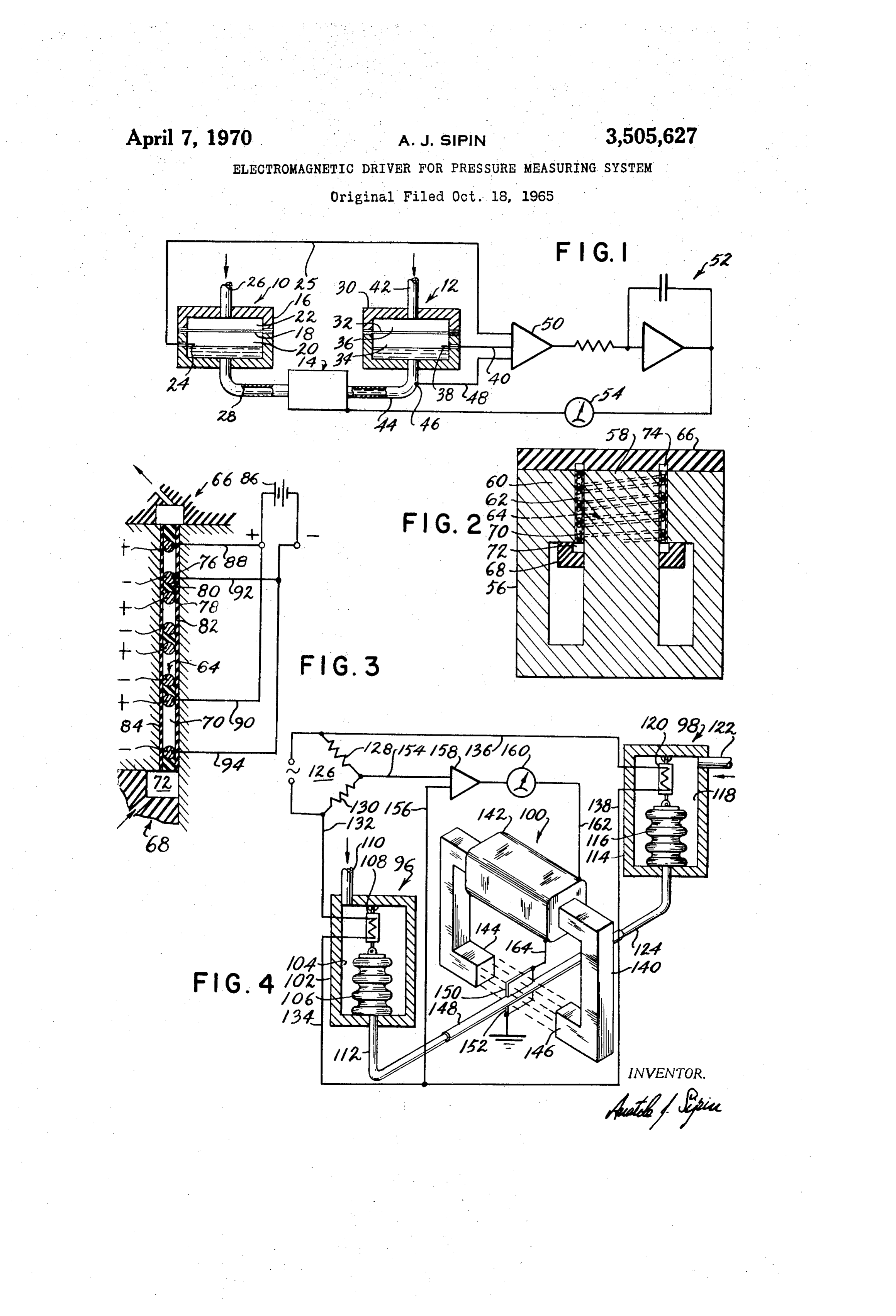
FIG. 1 is a schematic diagram of the pressure meas uring system showing a preferred form of the invention. FIG. 2 is a sectional elevation view of a preferred construction for the pressure balancing means shown in
FIG. 3 is a fragmentary view showing a detail of the pressure balancing device shown in FIG. 2.
FIG. 4 is a schematic diagram of another embodiment of the pressure measuring system.
Page 1drawing sheetscan →
Page 2scan →
Electromagnetic drever for pressure
Measuring system
Anatole J. Sipin, 117 E. 77th St.,
Original application Oct. 18, 1965, Ser. No. 497,000, now and this application Jan. 16, 1968, Ser. No. 718,961
Abstract of the disclosure
A magnetic driver for a pressure measuring system of the force balance type in which the restoring force of 5 the system is applied electromagnetically to a conductive fluid. The electromagnetic driver has a pair of opposite poles separated by an air gap, a plurality of fluid chan nels in said air gap, and spaced apart conductor means arranged such that the conductive fluid passes through 20 the channels in said air gap.
This is a division of application Ser. No. 497,000, filed
This invention relates to a system for measuring fluid 25 pressure over a wide range with high accuracy. Need exists in industrial processes and laboratory ap plications for an instrument that can measure absolute or differential pressure over a wide range with high sen 30 sitivity and high accuracy and that provides an electrical output for remote transmission that is not affected by transmission losses and interference.
Existing pressure transducers using the extension of an elastic member as a measure of applied pressure have 35 a resolution which is a constant fraction of the full scale output, limiting the range of measurement. Also, such transducers often have delicate electrical elements with very small voltage outputs or high internal impedances, making it necessary to shield signal leads, use amplifiers 40 with very high input impedances or take other measures to avoid spurious effects. Automatic manometers with follow-up systems have been constructed having high ac curacy and satisfactory electrical outputs. These instru ments, however, are complex and expensive; and their 45 range is limited by a practical height for the manometer tubes. Force balance instruments are known in which the unknown pressure is applied as a force on a member and an electrically generated restoring force is applied to balance the member. The restoring force provides a 50 measure of the unknown pressure. The pressure sensing member is typically an elastic member such as a bellows or diaphragm. It is difficult to provide high accuracy at high pressures with such devices. The restoring force is applied in relation to the deflection of the member. To 55 withstand high pressure the elastic sensing member is stiff; and the spring force opposed to deflection introduces errors associated with other transducers using elastic ele ments.
It is an object of this invention to provide a system for 60 measuring fluid pressure over a wide range with high accuracy.
It is another object of this invention to provide a sys tem for measuring high pressures with high accuracy. 65 It is a third object of this invention to provide a system for measuring small differential pressures at high values of absolute pressure.
It is a fourth object of this invention to provide a sys tem for measuring fluid pressure having an electrical 70 output which is not affected by transmission losses. It is a further object of this invention to provide a small and simply constructed device to meet the fore going objectives.
The invention is a pressure measuring system of the force balance type in which the restoring force is applied electromagnetically to a conductive fluid. Unknown pres sure is applied to a line containing electrically conductive fluid, moving the fluid. Motion of the conductive fluid is sensed by a pickup; and a pressure balancing device applies an electromagnetic force to the conductive fluid in accordance with the output of the pickup in a direction to null the fluid motion and restore a pressure balance. The force applied by the electromagnetic device is meas ured to indicate the unknown pressure. The pressure balancing device can be an electromagnetic driver of known configuration in which magnetic flux and electric current are passed through the conductive fluid in orthog onal directions transverse to the line to apply a pressure force to the conductive fluid in the line by motor action. The principal advantage of this system over previous force balance devices is that the feedback is applied di rectly as a pressure and that an additional movable mem ber is not essential to separate the unknown fluid from the environment. For example, the electromagnetic driver can be assembled between the branches of a U-tube mercury manometer; and level switches or other sensors used to detect motion of the mercury column from a reference position when pressure is applied. The ma nometer can be armored so that small values of differen tial pressure can be detected by the level sensor at high values of absolute pressure. If a permanent magnet or other constant field is applied, the current supplied to the electromagnetic driver is directly related to unknown pres sure. This current can be measured by an ammeter at long distances from the sensor; and it is unaffected by transmission line resistance.
Different embodiments of the invention are described hereinafter in connection with the following drawings, disclosing various specific features and advantages. In the drawings,
FIG. 1 is a schematic diagram of the pressure meas uring system showing a preferred form of the invention. FIG. 2 is a sectional elevation view of a preferred construction for the pressure balancing means shown in
FIG. 3 is a fragmentary view showing a detail of the pressure balancing device shown in FIG. 2.
FIG. 4 is a schematic diagram of another embodiment of the pressure measuring system.
The pressure measuring system shown in FIG. 1 in cludes a first pressure sensing member 10, a second pres sure sensing member 12, and an electromagnetic driver 14 connected to the pressure sensing members. Member 10 consists of a housing 10 with an internal cavity, a diaphragm 18, separating the cavity into two pressure chambers 20 and 22, an electrical contact 24 protruding into chamber 20, a lead 25 connecting contact 24 into an external circuit, a first tube 26, connecting chamber 22 to a source of unknown pressure, and a second tube 28 connecting chamber 20 to the electromagnetic driver. Member 12 includes housing 30, pressure chamber 34, contact 38 connected to lead 40 and fluid pressure tubes 42 and 44. The continuous channel formed by tubes 28 and 44 and electromagnetic driver 14 is filled with a conductive fluid, shown in FIG. 1 as a liquid, which also partially fills chambers 20 and 34. Electrode 46, insulated from tube 44, is immersed in the conductive liquid and connected into an external circuit through lead 48. Leads 25, 40 and 48 provide inputs to amplifier circuit 50, which supplies an imbalance signal to integrator 52, which in turn supplies driving current to the electromagnetic driver. The driving current is measured by indicator 54, which is calibrated in units of pressure.
Page 3scan →
Assuming that the pressure applied to chamber 22 ment 64 at one end by lead 88 and at the other end by lead through tube 26 is higher than that applied to chamber 34, 90. The negative terminal of the source is connected to the the level of conductive liquid in chamber 20 will fall while negative conductor 80 of element 64 at one end by lead 92 that in chamber 34 will rise. When the level in chamber 34 and at the other end by lead 94. has increased a small amount, the circuit between contact Assuming that the electrical polarities are as shown in 38 and electrode 46 will be closed, causing a constant volt FIG. 3, electrical current will flow from the positive con age of given polarity to be applied to integrator 52. The ductor to the negative conductor in a direction parallel to integrator delivers a continuously increasing value of elec the length of the air gap and perpendicular to the direction tric current to the driver, which electromagnetically applies of flux. Force is thereby applied to move the conductive an increasing pressure to the conductive liquid in a direc 10 fluid in a spiral direction parallel to the conductors of ele tion opposite to its motion until the null levels in both ment 64. The conductors are connected to the electrical chambers are restored, and the circuit between switch 38 Source at both ends to obtain a uniform distribution of and electrode 46 is again open. At this point the electro current density. The applied force per unit length of the magnetic pressure exactly balances the unknown pressure channel depends only on the flux density and the magnitude differential applied to chambers 22 and 34. The electro 5 of electric current. By making the cross-sectional area of magnetic pressure is also linearly related to the electrical the flow channel small, the pressure achieved can be very current; and ammeter 54 is calibrated directly to indicate high. This can be done by minimizing the width of the air the unknown pressure. gap, which has the beneficial effect of increasing flux den If the pressure in chamber 34 exceeds that in chamber sity. Thus, high balancing pressures can be attained with a 22, the circuit between contact 24 and electrode 40 is 20 relatively small magnetic structure and relatively low closed, a current of opposite polarity is fed to the electro values of current. The advantage of the invention can be magnetic driver and meter 54 indicates the negative pres appreciated by comparing the balancing means with those sure differential. of conventional force feedback systems, where the balance If one of the chambers 22 and 34 is exposed to atmos pressure depends on the such larger cross-sectional area of phere, meter 54 will indicate gauge pressure or vacuum. 25 an elastic member.
The meter will indicate absolute pressure if one of the An AC source as well as a DC source can be utilized for chambers is evacuated. the electrical current if the magnetic field is created by a As shown in FIG. 1 the space between the liquid and coil energized by a constant voltage at the same frequency. diaphragm in chamber 20 is charged with gas. It is to be The structure for an electromagnetic driver shown in understood that the diaphragm is slack and that the gas 30 FIGS. 2 and 3 has advantages in other applications be volume varies so that its pressure is always that of the fluid sides pressure measurement. It can be used as a calibrated in the chamber separated by the diaphragm. Alternatively, pressure Source for test purposes. It can also be used in a the space can be filled with a non-conductive liquid of modified circuit of FIG. 1 as a pressure switch. The am lower specific gravity than the conductive liquid, in which plifier and integrator are removed, and the bias force for event there will be insignificant volume change. Also the 35 switching the contacts is adjusted by varying electrical cur conductive liquid can be made to entirely fill chamber 20 rent to driver 14. This device can be used as a high current and closure made between movable contacts on the slack relay.
diaphragm and fixed contact in chamber 22. It is to be The pressure measuring system shown schematically in understood that pressure sensing members 10 and 12 are FIG. 4 is advantageous for flow measurements as it indi only illustrative of means to contain the volume of con 40 cates the square root of applied pressure. The system in ductive fluid within the system and to apply an unknown cludes two pressure sensing members 96 and 98 and an pressure to the line. Both pressure sensing members can electromagnetic driver 100. The first member 96 consists include chambers sealed by flexible diaphragms, of which of a housing 102, with an internal cavity 104, a bellows chamber 20 in sensing member 10 is an example. Or the 106, sealed from the internal cavity, with one end fixed to chambers can be replaced by bellows. If the conductive 45 the housing, a strain gage 108 with one end fixed to the fluid is a liquid, both pressure sensing members can be housing and the other end attached to the movable end of constructed as is member 12, with a single chamber 34 to the bellows, a tube 110 leading unknown fluid pressure into act as a reservoir, containing the conductive fluid in the cavity 104 and another tube 112 leading conductive fluid to line. Here the unknown fluid pressure is applied directly the interior of the bellows from the electromagnetic driver. to the conductive liquid in the chamber. 50 Pressure sensing member 98 similarly consists of housing It is to be understood that all elements shown merely 114 with cavity 118, bellows 116, strain gage 120 and tubes illustrate the function performed. Amplifier 50, for ex 122 and 124. Strain gages 108 and 120 are connected into a ample, could be a relay; and integrator 52 could be a bridge circuit with resistors 128 and 130 through leads 132, motor-driven potentiometer. 134, 136 and 138.
FIGS. 2 and 3 show details of construction of a pre 55 The electromagnetic driver consists of an electromagnet ferred form of electromagnetic driver 14 in FIG. 1. The 140 with a field coil 142 and poles 144 and 146. A channel driver includes a magnet 56 having an axis with two coaxial 148 leads conductive fluid past the poles with a flow path poles, 58 with an external cylindrical face, and 60 with an perpendicular to the direction of magnetic flux. Electrodes internal cylindrical face, and an annular air gap 62 between 150 and 152 apply electric current to the conductive fluid the pole faces. A ribbon element 64 is spirally placed about 60 in a direction perpendicular to both the flow path and the the axis in the air gap, providing a continuous channel for direction of flux, thus applying pressure force to the con conductive liquid in the air gap. Electrically insulating ductive fluid along the flow path. cover 66 seals one end of the air gap and insulating cover Leads 154 and 156 apply the bridge imbalance voltage to 68 seals the other end of the air gap. A continuous passage amplifier 158, which applies the same electric current to the for conductive liquid between inlet tube 44 and outlet tube 65 field coil through lead 162 and thence to the electrodes, 28 is provided by spiral channel 70, formed between adja which are series connected to the field coil through lead cent layers of element 64 and connecting with channel 72 164. Ammeter 160 measures the current and can be cali in cover 68 and channel 74 in cover 66. The ribbon element brated in units of flow or the square root of pressure. This is an assembly of a negative electrical conductor 76 and a positive electrical conductor 78 separated by an electrical 70 is so because the balance pressure is proportional to the insulator 80. Pole 58 is insulated by layer 82 and pole 60 is product of magnetic flux and current. Since the magnetic insulated by layer 84. Element 64 is bonded to both pole flux is here proportional to the current, the balance pres faces to seal the liquid channel between conductors of ad Sure is proportional to the square of the current; and since jacent turns. The positive terminal of a source of electric the unknown pressure equals the balance pressure, the cur current is connected to the positive conductor 78 of ele 75 rent measurement indicates square root of pressure.
Page 4scan →
The system of FIG. 4 operates essentially the same as nels in the air gap with parallel flow axes perpendicular that of FIG. 1 except that the output of the strain gage to the direction of magnetic flux between the field poles, bridge, sensing bellows displacement, is proportional to each channel having a positive and a negative conductor applied pressure. Other proportional displacement sensors parallel to the flow axis and separated by a flow area, said can be used, such as variable capacitors, differential trans channel and conductors being electrically insulated from formers and potentiometers. A carbon pile can also be the field poles and the other channels, the channels being used to sense unbalanced pressure force applied by the connected in series to form a continuous flow path for con bellows. Here the carbon pile acts a a variable resistor ductive fluid in the air gap, and means to connect the posi directly in series with the leads of the electromagnetic tive conductor to a source of positive voltage and the driver and the amplifier can be eliminated. negative conductor to a source of negative voltage. One advantage of the invention is that the diaphragm 10 2. In a system of the character described, an electro and bellows sealing members can be very flexible as there magnetic driver with internal and external cylindrical is substantially no pressure across them in operation. This magnetic field poles having a common axis separated by an reduces pressure sensing error due to stiffness of the seal annular air gap, the opposing faces of said poles in the air ing member to a negligible level, whereas such an error gap being electrically insulated, a ribbon element spirally is significant in devices where the member must seal the placed about the pole axis within the air gap and sealed to fluid from the atmosphere. the pole faces, said element consisting of a positive elec The system herein described can be utilized in many trical conductor and a negative conductor separated by an applications requiring detection of changes in fluid pres insulator, the spiral element forming boundaries of a sure. It can be used as a pressure control system, in which 20 continuous spiral channel within the air gap between the case a selected value of current is applied to the electro positive and negative conductors of adjacent turns of the magnetic driver to establish a pressure reference, and the element to contain electrically conductive fluid, the chan pressure imbalance signal is fed to a control device in a nel terminating at one end in an insulated inlet chamber direction to restore pressure balance. The system can also and at the other end in an insulated outlet chamber, a be used to measure or control temperature, in which case 25 port to lead conductive fluid into the inlet chamber and the unknown pressure, proportional to temperature, is another port to lead conductive fluid from the outlet cham supplied from a temperature sensing element, such as a ber, leads to connect the positive conductor of the ribbon fluid-charged bulb. The system can also be used to meas element to a source of positive electricity and leads to ure or control liquid level, where the unknown pressure is connect the negative conductor of the element to a source directly related to the level of liquid being sensed. m 30 of negative electricity.
While the invention has been described in its preferred embodiments, it is to be understood that the words which References Cited have been used are words of description rather than of UNITED STATES PATENTS limitation and that changes within the purview of the ap pended claims may be made without departing from the 35 2,583,724 1/1952 Broding.
true scope and spirit of the invention in its broader as 3,034,002 5/1962 Carlson.
pects.
What is claimed is: GEORGE HARRIS, Primary Examiner 1. In a system of the character described, an electro magnetic driver with magnetic field poles of opposite 40 U.S. C. X.R.
polarity separated by an air gap, a plurality of fluid chan 73-398
Provenance
- Collection
- Patents citing this work
- Pages
- 4
- Method
- pdftotext (the PDF's own text layer) + pdftoppm 300dpi page scans
- Patent office record
- patents.google.com →
- Source
- Google Patents citing-documents table
- Assignee
- Anatole J Sipin
- Published
- 1970-04-07
- Transcribed from
- patentimages.storage.googleapis.com →