

patent · US4469471A
Electromagnetic flow coupler
4 September 1984
Text
Page 1bibliographic recordscan →
. . . . . . SR
United States Patent (19) Patent Number: 4,469,471 Keeton et al. Date of Patent: Sep. 4, 1984 (54) ELECTROMAGNETC FLOW COUPLER 3,280,349 10/1966 Brenner et al. ....................... 310/11 3,401,278 9/1968 Ho ......................................... 310/11 Inventors: Alvin R. Keeton, Finleyville; Philip
A. Ciarelli, Jr., Clarksburg, both of FOREIGN PATENT DOCUMENTS
(73) Assignee: Westinghouse Electric Corp.,
Pittsburgh, Pa. Primary Examiner-Edward K. Look
Attorney, Agent, or Firm-L. A. DePaul
(22) Filed: Jun. 22, 1982 (57) ABSTRACT (51) Int. Cl. ............................................. HO2K 44/00 The electromagnetic flow coupler comprises substan (52) U.S. C. ......................................... 417/50; 310/11 tially electrically insulated side walls for minimizing 58 Field of Search ............................. 417/50; 310/11 parasitic losses in the side walls. The side walls may comprise alumina plates attached to conductive mem (56) References Cited bers with thin stainless steel plates disposed on the in
2,715,190 8/1955 Brill .................................. 417/50 X electricity through the side walls of the flow coupler.
3,034,002 5/1962 Carlson ................................. 310/11 3,271,597 9/1966 Way ...................................... 310/11 8 Claims, 4 Drawing Figures
NNYS
64-p NWill 2N NWLAN
Drawings
Page 2drawing sheetscan →
Page 3drawing sheetscan →
Page 4scan →
current losses and permit higher overall efficiencies, on
ELECTROMAGNETC FLOW COUPLER the order of 60%, to be attained.
While flow couplers are capable of increasing elec
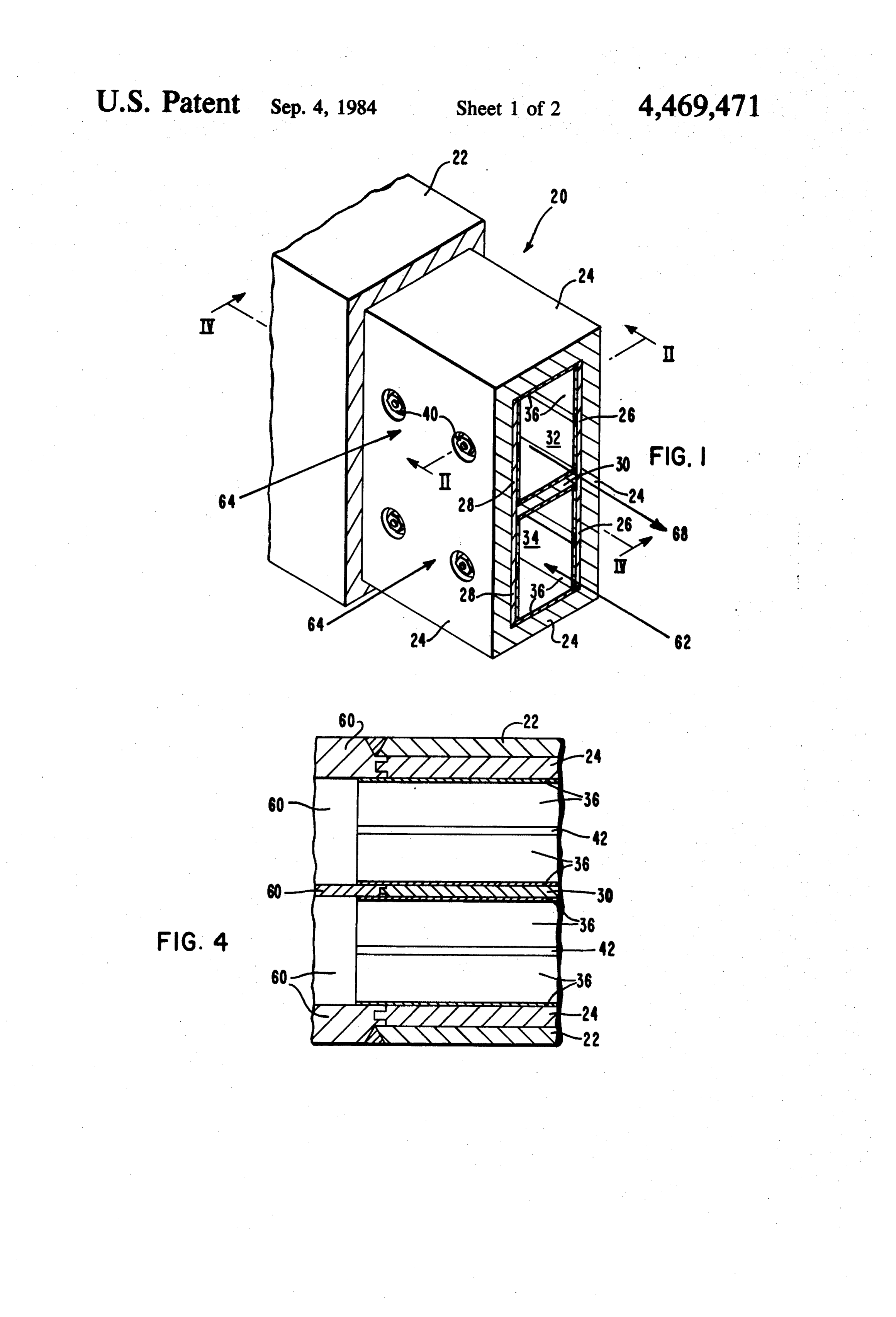
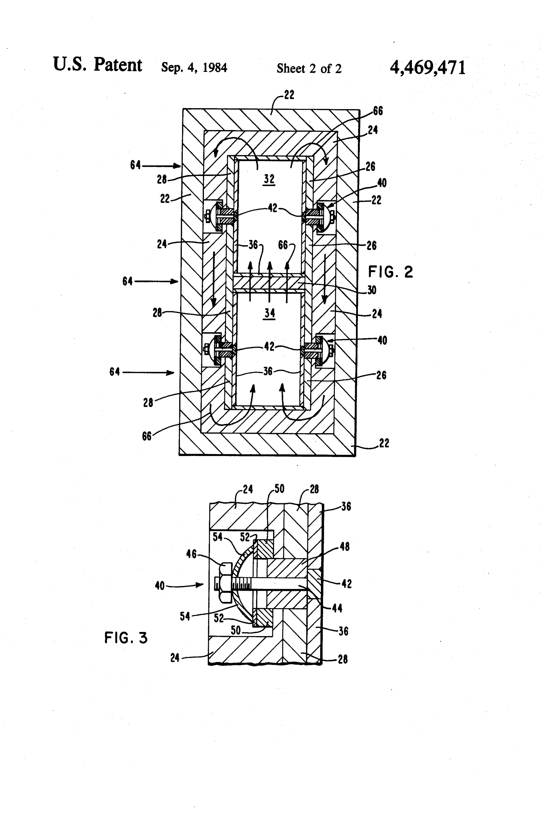
BACKGROUND OF THE INVENTION tromagnetic pump efficiencies, further reduction of This invention is related to electromagnetic pumps 5 parasitic containment wall losses would be desirable. and more particularly to electromagnetic flow couplers. Therefore, what is needed is an electromagnetic flow As is well known in the art, electromagnetic pumps coupler constructed to minimize parasitic current losses produce a pressure differential or a pressure head be in the duct walls of the flow coupler. tween the inlet and the outlet through the interaction of SUMMARY OF THE INVENTION an electrical current and a crossed magnetic field. This O interaction produces an electromagnetic force density The electromagnetic flow coupler comprises substan throughout the volume of the fluid within the pump tially electrically insulated side walls for minimizing region wherever both the current density and the mag parasitic losses in the side walls. The side walls may netic field are non-zero. At each such point, this force is 15 comprise alumina plates attached to conductive mem proportional not only to the magnitude of the current bers with thin stainless steel plates disposed on the in density and magnetic field, but also to their relative side walls of the alumina plates for reducing the flow of orientation. The maximum force density and resulting electricity through the side walls of the flow coupler. pressure differential occurs when the electrical current and the magnetic field are mutually perpendicular to 20 BRIEF DESCRIPTION OF THE DRAWINGS each other and to the direction of fluid flow. While the specification concludes with claims partic Typically, the electromagnetic pumps are con ularly pointing out and distinctly claiming the subject structed in a rectangular duct by mounting two elec matter of the invention, it is believed the invention will trodes flush with the opposite side walls of the duct and be better understood from the following description placing the other two walls between magnetic pole taken in conjunction with the accompanying drawings, faces. When the two electrodes are connected to an 25 wherein:
external power supply, current flows across the duct FIG. 1 is a cross-section view in perspective of the and interacts with the magnetic field to produce the flow coupler ducts;
axially directed body force and pressure difference FIG. 2 is a view along line II-II of FIG. 1; across the duct. The pump's inlet and exit regions are defined roughly by the electrode edges. These regions 30 FIG. 43 isis aanview
FIG. enlarged view of the fastener; and along line IV-IV of FIG. 1.
may vary somewhat depending upon the relative loca tion of the magnetic pole face edges. In an ideal pump, DESCRIPTION OF THE PREFERRED all the current would be confined to the duct volume EMBODIMENT enclosed by the electrodes and the pole faces where the Referring to FIGS. 1 and 2, the electromagnetic flow force density is the greatest. In an actual pump, how 35 coupler is referred to generally as 20 and comprises an ever, some current leaks into the magnetic fringe region outer duct 22 which may be a heavy-walled 316 stain both upstream and downstream from the electrode less steel duct for providing mechanical strength and a edges. This tends to lower pump efficiency. Thus, cur leak-proof boundary for flow coupler 20. An electri rent leakage in the magnetic fringe regions adds little to the overall pressure differential while increasing the copper is disposed withinduct cally conductive inner 24 which may be made of outer duct 22. A first insulator current flow thereby diminishing efficiency.
In general, the problems with electromagnetic pumps 26 is disposed on the inside of and along one wall of fall into two categories: (1) obtaining suitable high cur inner duct 24 and a second insulator 28 is disposed on rent power supplies, and (2) minimizing parasitic losses the inside of and along the opposite wall of inner duct in the containment walls of the pump. Parasitic losses in 45 24. First insulator 26 and second insulator 38 may be the containment duct walls of electromagnetic pumps alumina plates that extend along the respective walls of account for much of its low efficiency which may be in inner duct 24 the length of flow coupler 20 and serve to the range of 10 to 40%. To overcome the problems of direct the flow of electric current and minimize para obtaining a suitable high current power supply and to sitic current losses. An electrically conductive divider minimize parasitic losses, two electromagnetic pumps 50 plate 30, which may be copper, may be disposed in may be arranged side-by-side in a common magnetic about the middle of inner duct 24 perpendicular to and field with one such pump acting as an electromagnetic attached at one end to first insulator 26 and at the other generator and the other acting as an electromagnetic end to second insulator 28. Divider plate 30 extends pump. This arrangement of electromagnetic pumps is approximately the length of first insulator 26 and sec commonly referred to as a "flow coupler'. 55 ond insulator 28 and divides flow coupler 20 into two In a typical flow coupler, a liquid metal is caused to separate but adjacent flow channels, first channel 32 and flow through the generator section of the flow coupler. second channel 34.
Passage of the fluid through the common magnetic field First channel 32 and second channel 34 are lined with generates a large current which is transferred to the thin plates 36 of 316 stainless steel and channel the flow pump section by short, low resistance electrodes. Inter of liquid metal therethrough. The use of a corrosive action of the current in the pump section with the com resistant material such as stainless steel provides a mon magnetic field produces flow in the pump section. means to protect first insulator 26 and second insulator In this manner, the flow of a first liquid metal in the 28 from the corrosive environment of the liquid metal generator section is "coupled" to the flow of a second 65 without detracting from the insulating quality of first liquid metal in the pump section. The local generation insulator 26 and second insulator 28. Plates 36 are of the current enables lower voltages and higher cur bonded to inner duct 24 at surfaces not separated by rents to be used than would be possible with an external insulators 26 and 28 and to divider plate 30 by a con power supply. The lower voltages, in turn, reduce end mon joining method such as brazing. Plates 36 are also 5 attached to first insulator 26 and second insulator 28 by first channel 32 by the electric current which causes the means of attachment mechanisms 40. liquid in first channel 32 to flow in the direction of Referring now to FIGS. 1-3, attachment mechanism arrow 68. In this manner flow coupler 20 provides a 40 comprises a stainless steel rib 42 which may be means for allowing the flow of a first liquid metal to welded along the length of the plates 36 which are 5 pump a second liquid metal in separate flow channels. adjacent first insulator 26 and second insulator 28. In We claim as our invention:
general, only plates 36 which are disposed against first 1. An electromagnetic flow coupler comprising: insulator 26 and second insulator 28 need be held by a an outer duct;
rib 42 with the remaining plates 36 being capable of a substantially rectangular electrically conductive being bonded directly to inner duct 24 and divider plate 10 inner duct disposed within said outer duct for con 30. A stud 44 which is attached at one end to rib 42 and ducting an electric current therethrough; at the other end to nut 46 is disposed in an alumina a first insulator and a second insulator disposed along bushing 48 which is located in a recessed portion of opposite inside walls of said inner duct for minimiz inner duct 24. An alumina washer 50 is disposed on ing the flow of electricity through said insulators; inner duct 24 and around stud 44 and has a stainless steel 15 an electrically conductive divider member disposed washer 52 disposed on the top thereof. A stainless steel in said inner duct and between said first insulator Belleville washer 54 is clamped onto washer 52 by and said second insulator thereby dividing said tightening nut 46 on stud 44. The tightening of nut 46 on inner duct into a first channel and a second channel stud 44 causes rib 42 to be drawn tightly against bushing for conducting two separate electrically conduc 48 thereby holding plates 36 against first insulator 26 or 20 tive fluids therethrough; and second insulator 28 without compromising the insulat a plurality of electrically conductive corrosion resis ing qualities of first insulator 26 or second insulator 28. tant plates disposed in said first and second chan This is accomplished by the selective use of alumina nels for lining said channels. insulating members such as bushing 48 and washer 50. 2. The electromagnetic flow coupler according to Thus a conductive path is prevented from being estab 25 claim 1 wherein said plates are stainless steel plates. lished between plates 36 and inner duct 24. This also 3. The electromagnetic flow coupler according to provides a means of accommodating differential ther claim 2 wherein said first insulator and said second mal expansion between copper, alumina, and stainless insulator are alumina.
steel components. 4. The electromagnetic flow coupler according to Referring now to FIG. 4, the flow coupler 20 may be 30 claim 3 wherein said inner duct is copper. terminated by means of a stainless steel flange 60. Plates 5. The electromagnetic flow coupler according to 36 may be welded around their entire perimeter to claim 4 wherein said outer duct is stainless steel. flange 60 thus hermetically sealing first channel 32 and 6. The electromagnetic flow coupler according to second channel 34. Outer duct 22 may also be welded to claim 5 wherein said divider member is copper. flange 60 to complete the sealing of the outer wall of 35 7. The electromagnetic flow coupler according to flow coupler 20. Inner duct 24 and divider plate 30 are claim 1 wherein said flow coupler further comprises an tongue and groove fitted to flange 60 for assembly and attachment support. Sufficient clearance is allowed between the connected tomechanism disposed in said inner duct and tongue and groove fittings to accommodate differential plates against atatleast one of said plates for holding said thermal expansion between the copper and stainless 40 venting the flow least of one of said insulators while pre electricity from said plates to said steel members. In addition, a gasket is provided in the inner duct through said attachment mechanism. tongue and groove fitting to electrically insulate the 8. The electromagnetic flow coupler according to copper members from the stainless steel members. In claim 7 wherein said attachment mechanism further addition, suitable piping may be connected to first chan comprises:
nel 32 and to second channel 34 to independently con 45 a stainless steel rib extending along the length of and duct the liquid metal in separate flow paths. connected to one of said plates; 8. Referring now to FIGS. 1 and 2, flow coupler 20 a stud connected to said rib and extending through operates on the principle that a liquid metal such as sodium flowing under the influence of a pump (not one of said insulators and through said inner duct; shown), through a channel such as second channel 34 in 50 antween alumina bushing disposed around said stud be said steel and said one of said insulators for the direction of arrow 62 and in the presence of a mag netic field as indicated by arrows 64, generates an elec preventing contact between said stud and said insu tric current in a direction mutually perpendicular to the lator;
plane formed by the flow direction vector and the mag an alumina washer disposed in said inner duct and netic flux vectors. Second channel 34, therefore, be 55 around said stud;
comes a DC generator with electric current flowing out a stainless steel washer disposed around said stud and its top boundary and returning through its bottom on said alumina washer;
boundary as indicated by arrows 66. Since the side walls a stainless steel Belleville washer disposed on said are quasi-insulated by first insulator 26 and second insu stud as in contact with said stainless steel washer; lator 28, the generated current is forced to flow through 60 and first channel 32. Electric current flowing through a a nut disposed on said stud for drawing said stainless liquid in the presence of a magnetic field produces a steel washer against said alumina washer and for force mutually perpendicular to the current and mag drawing said rib against said bushing when said nut netic flux vectors. Thus, first channel 32 becomes a is tightened on said stud thereby drawing said pump with the hydraulic energy from the liquid stream 65 plates against said insulators.
in second channel 34 transferred to the liquid stream in
Provenance
- Collection
- Patents citing this work
- Pages
- 5
- Method
- pdftotext (the PDF's own text layer) + pdftoppm 300dpi page scans
- Patent office record
- patents.google.com →
- Source
- Google Patents citing-documents table
- Assignee
- Westinghouse Electric Corp.
- Published
- 1984-09-04
- Transcribed from
- patentimages.storage.googleapis.com →