

patent · US3603823A
Magnetic motor with plurality of stators
7 September 1971
Text
Page 1bibliographic recordscan →
United States Patent Inventor Elmer B. Mason 901 Vickie Dr., Oklahoma City, Okla.
(54) MAGNETIC MOTOR WITH PLURALITY OF
STATORS
2 Claims, 11 Drawing Figs.
(52) U.S. Ch........................................................ 310/46,
(5) Int. Cl.................. ... H02k 23/36 50 Field of Search............................................ 310/46, 67,
UNITED STATES PATENTS
1,545,422 7/1925 Graichen...................... 310/23 2,194,21 1 3/1940 310/46X 3,471,728 10/1969 310/231 X 3,534,203 10/1970 31 0146X
153,456 7/1874 Paine............................ 30/46 1,764,714 6/1930 Boykow........................ 30/67 X 1934,766 l l 11933 Krussmann................... 310/12 2,273,840 2/1942 Dever........................... 30/67 3,308,318 3/1967 Dunaiski et al............... 310/67 X 3,396,296 8/1968 Esters........................... 310/46X Primary Examiner-D. F. Duggan
Attorney-Robert K. Rhea
ABSTRACT: An electric motor frame is defined by spaced apart generally circular end members which coaxially journal a rotor comprising a drive shaft having a disklike flange secured thereto medially the spacing of the end members. Sta tor coils are concentrically secured to the inner surface of at least one end plate and field coils are secured to at least one side surface of the rotor in concentric outwardly spaced rela tion with respect to the stator coils. Brush rigging, connected with the rotor, supports a pair of brushes interposed between a commutator and slip rings concentrically surrounding the drive shaft and supported by one frame end member to complete a current switching action to the stator coils.
Drawings
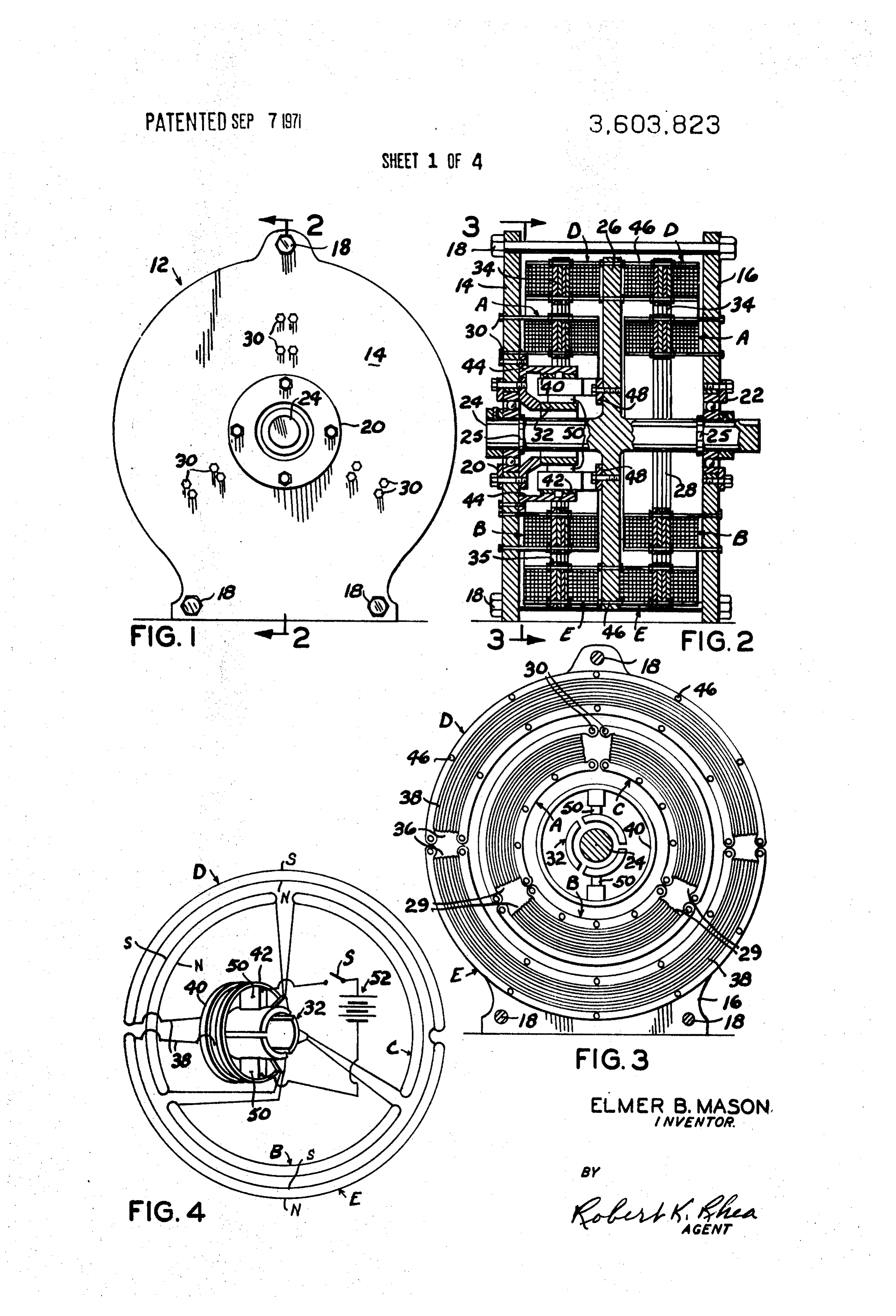
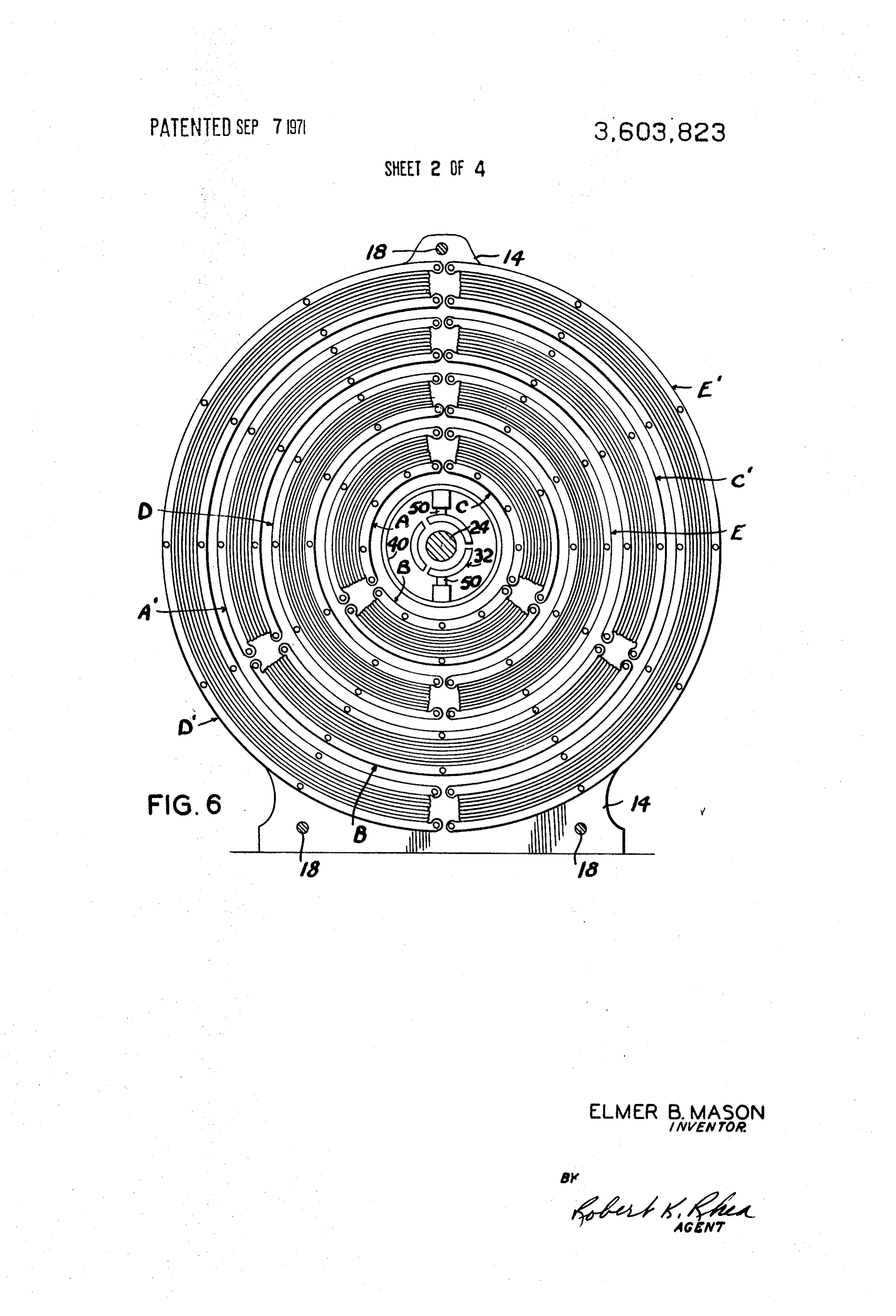
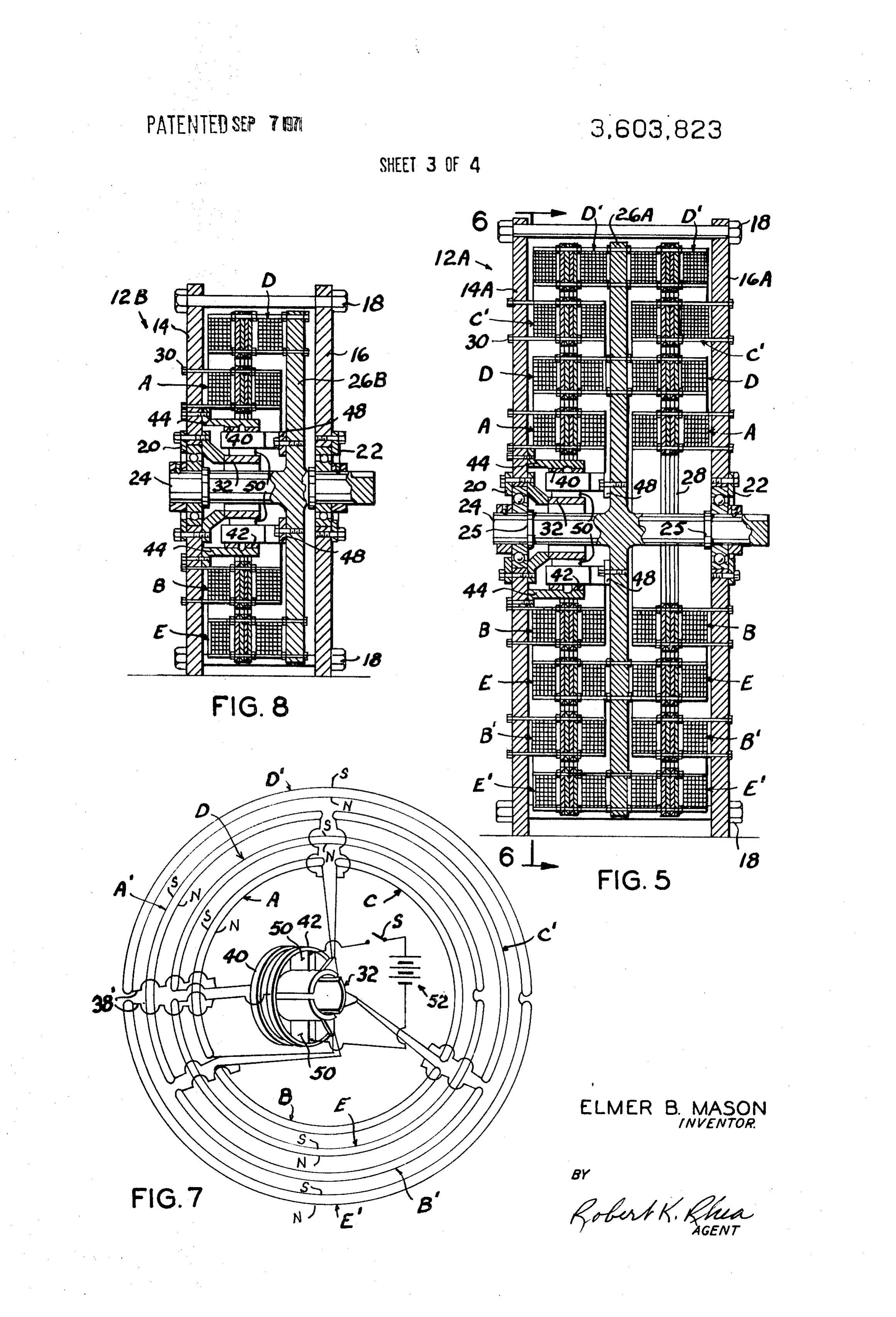
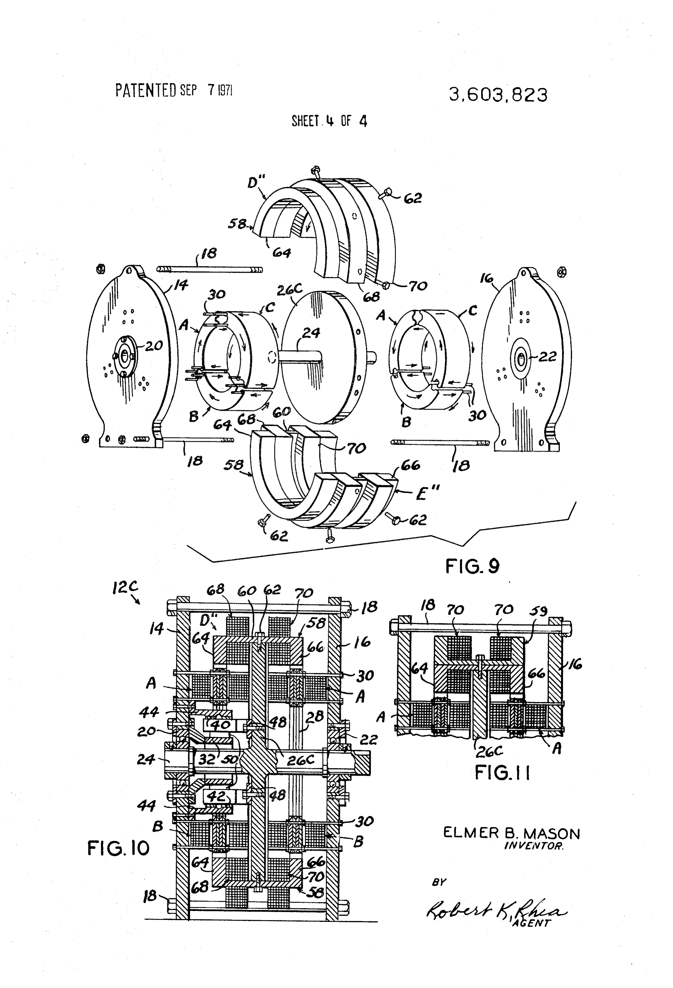
FIG. 6 is a vertical cross-sectional view, partially in eleva
FIG. 1 is an end elevational view of the motor;
FIG. 2 is a vertical cross-sectional view, partially in eleva 70 38, coil after being wound around the coil plates 34 to form the
Page 2drawing sheetscan →
Page 3drawing sheetscan →
Page 4drawing sheetscan →
Page 5drawing sheetscan →
Page 6scan →
FIG. S is a view similar to FIG. 2 of a dual stage embodiment
MAGNETIC MOTOR WITHPLURALITY OF STATORs of the motor;
FIG. 6 is a vertical cross-sectional view, partially in eleva
BACKGROUND OF THE INVENTION tion, taken substantially along the line 6-6 of FIG. 5; FIG. 7 is a wiring diagram of the left hand half of the motor 1. Field of the Invention as viewed in FIG. 5;
The present invention relates to electric motors and more FIG. 8 is a view similar to FIG. 2 of an alternative embodi particularly to single and multistage concentric motors having ment of the motor;
stator coils spaced inwardly of rotating field coils for increas 10 FIG. 9 is an exploded perspective view of another embodi ing the torque of the drive shaft. ment of the motor;
Conventional electric motors comprise a generally circular FIG. 10 is a vertical cross-sectional view, partially in eleva frame which journals a drive shaft. The frame supports stators tion, of FIG. 9 when assembled; and, or field windings, either permanent or electromagnets, while FIG. 11 is a fragmentary vertical cross-sectional view of an the drive shaft supports an armature formed by winding a plu 5 alternative embodiment of the motor illustrated in FIG. 10. rality of coils thereon concentrically disposed within the sta tors or field coils. Brushes, supported by brush rigging con DESCRIPTION OF THE PREFERRED EMBODIMENTS nected with the frame, contact a commutator formed on one Like characters of reference designate like parts in those end of the armature control the direction of current through FIGURES of the drawings in which they occur. the coils. Conventional electric motors thus utilize the arma 20 In the drawings:
ture as a rotating switch and power source. Referring more particularly to FIGS. 1 to 4, the reference In this invention positioning the armature coils or windings numeral 12 indicates a DC motor which is cylindrical in concentrically outward of the drive shaft, fixing their position to form stator coils and mounting the field coils or magnets general configuration comprising a pair of generally circular outwardly of the stator coils for rotation therearound, in 25 end a plates 14 and 16 connected in parallel spaced relation by plurality of bolts 18. The end plates 14 and 16 are centrally creases the torque on the drive shaft by a leverage factor apertured for respectively receiving bearings 20 and 22 which which increases for each increment of radially outward spac journal ing, from the drive shaft, of the stators and rotatingfield coils. each of its endsorand an axle drive shaft 24 having shoulders 25 adjacent having an integral disklike flange inter 2. Description of the Prior Art
U.S. Pat. Nos. 294,043; 2,550,571 and 3,069,577 relate to 30 rotor 26. Two sets, eachdiameter mediate its ends of less than the end plates forming a comprising a series, three in the ex axial gap squirrel cage type motors. ample shown, of armature magnets or coils A, B and C, each The principal distinction between this invention and the coil describing an arc of a circle, are disposed in a circular prior art patents resides in the structural arrangement of fix array and connected respectively to the inner surface of the edly connecting the armature coils and a commutator to the motor housing and securing the field magnets or coils to a 35 end plates 14 and 16 concentric with respect to the axle 24. Each of the coils A, B and Care substantially identical and are rotor so that the fields are disposed in concentric rotating rela formed by multilayers, four in the example shown, of soft iron tion outwardly of the armature coils. Furthermore, this inven core or coil plates 28 arranged edgewise in the circular plane, tion utilizes more of the magnet flux field by a plurality of con within the respective coil, and in contiguous face to face con centric stagging of stators and rotating field coils for increas tact. The respective end portions of the assembled coil plates ing the torque on the drive shaft. 40 are transversely notched or cut away to form a wire receiving
SUMMARY OF THE INVENTION and supporting recess 29. The coil plates 28 are secured to the A motor frame comprising generally circular spaced-apart respective end plates 14 and 16, intermediate the spacing between the end plates and the adjacent side surface of the platelike end members which horizontally journal a drive shaft 45 rotor 26, by bolts 30. Each of the coils A, B and C further in having a disklike flange forming a rotor medially the frame cludes a length of wire which is wound around the lateral sides ends. A plurality of iron core stator coils are concentrically of the coil plates 28, prior to their connection with the end secured to the inner surface of at least one end plate in radially plates, outwardly spaced relation with respect to the drive shaft. A sides ofasthea assembledcontinuous length of wire extending along both pair of iron core field coils is concentrically secured to a 50 29 formed at respectivecoilends plates 28 and through the recesses thereof thus forming magnetic cooperating face of the rotor for rotation of the field coils coils. Each end of the wires forming around the stators. An additional stage or stages comprising connected, respectively, with adjacentthesegments coils A, B, and C is rfixed stator coils and rotating field coils may be concen segment commutator 32 concentrically supported,ofin aspaced three ically added as desired and permitted by the physical size of the motor. Brush holders, connected with the rotor, support a 55 relation, around the axle 24 by and electrically insulated from the bearing 20. These stator coils A, B and C, when energized, pair of brushes in contact with a commutator concentrically as surrounding the drive shaft and connected with a frame end andhereinafter a south explained, each form a north pole N at one side pole Sat its opposite side (FIG. 4).
en hile slip rings, surrounding the brush holders and supported by the frame end member, connect a source of elec andTwo sets, each comprising a pair of field coil windings D. E, with each coil defining a substantially semicircular arc, are mounted, respectively, on opposite sides of an outer peripheral portion of the rotor 26 in concentric spaced rela
The principal object of this invention is to provide an elec tion with respect to the two sets of stator coils A, B and C for tric motor having a concentric rotor-stator coil configuration a similartherearound.
rotation Each of the field coils D and E comprise plurality of soft iron core or coil plates 34 and 35,- having a high efficiency rating and a higher torque on its drive 65 respectively, each having similar recesses 36 at their ends, shaft than conventional motors. respectively defining a socket for nesting a wire 38 wound. BRIEF DESCRIPTION OF THE DRAWINGs laterally around the respective coil plates in a similar manner with respect to the stator coils with the exception that the wire
FIG. 1 is an end elevational view of the motor;
FIG. 2 is a vertical cross-sectional view, partially in eleva 70 38, coil after being wound around the coil plates 34 to form the
D, is extended or continued for winding around the coil tion, taken substantially along the line 2-2 of FIG. 1; plates 35 to form the coil E thus joining the coils D and E inse FIG. 3 is a vertical cross-sectional view, partially in eleva ries. Each end of the wire 38 is connected, respectively, to a tion, taken substantially along the line 3-3 of FIG. 2; pair of slip rings 40 and 42 concentrically surrounding, in FIG. 4 is a wiring diagram of the left hand half of the motor spaced relation, the axle 24 and commutator 32 and sup as viewed in FIG. 2; 75 ported by brackets 44 connected with the inner surface of the 7 end plate 14. A plurality of bolts 46 extend transversely nected with the axle. Two sets of the stator field coils A, B and through the respective sets of coil plates 34 and 35 and the C are similarly concentrically connected with the inner sur rotor 26 for mounting the sets or pairs of coils D and E faces of the respective end plates 14 and 16. The field coils, in thereon. dicated at D'' and E', comprise a pair of substantially semicir A brush rack assembly 48 is interposed between the com cular members 58, U-shaped in cross section and having a mutator 32 and slip rings 40 and 42 and is adjustably con bight portion 60 contiguously contacting the outer peripheral nected with the rotor 26 for supporting a pair of commutator surface of the rotor flange 26C and secured thereto by bolts brushes 50. A battery 52 has its terminals connected respec 62 so that the respective leg portions 64 and 66 of the U tively to the brushes 50 for energizing the sets of stator coils A,shaped members 58 project toward, in circumferential spaced B and C and sets of field coils D and E when a switch S, inter O relation, the respective iron coil plates 28 of the sets of stator posed in the positive battery cable, is closed. The direction of coils A, B and C. The field coils D'' and E' further include winding of the stator coils A, B and C and the armature coils D coil windings 68 and 70 which are respectively formed by and E results in the magnet flux attraction and repulsion winding a wire longitudinally around the respective U-shaped between the stators and the field coils being equal and op 15 member from end to end along the outer surface of the respec posite to each other so that there is no resultant end thrust of a tive U-shaped member and in the spacing between the respec material magnitude operating on the rotor. Placing the arma tive leg 64 and 66 and the adjacent surface of the rotor flange ture windings D and E radially outward of the stator coils 26C so that the inner limit of the windings forming the field takes advantage of the flywheel effect and adds to the torque coils D'' and E' is radially spaced outwardly of that portion of on the axle or shaft 24 by reason of the leverage advantage ob the respective stator coils A, B and C disposed adjacent the tained by the radially outward spacing of the rotating sets of respective side surfaces of the rotor flange 26C. The windings field coils D and E. of the stator coils A, B and C on one side of the rotor are Referring now more particularly to FIGS. 5, 6 and 7, a identical whereas the stator coils A, B and C on the opposite modified form of the motor is illustrated at 12A which is sub side of the rotor are wound in reverse or cross wired in order stantially a diametrically greater sized version of the motor 12 25 to match polarity of the field coils D'' and E'. As viewed in comprising end plates 14A and 16A similarly journaling an FIG. 10, the leg 64 of the field coil D' will be a north pole axle or drive shaft 24A having an enlarged rotor 26A in while its other leg 66 is a south pole. The leg 64 of the field tegrally joined therewith. The motor 12A includes the two sets coil E' becomes a south pole and its other leg 66 is a north of stator coils A, B and C and field coils D and E. Two addi pole. The wires forming the sets of stator coils A, B and C and tional sets each comprising three stator coils A, B and C are 30 field coils D'' and E' are similarly connected to the battery similarly constructed and connected with the inner surface of through the switch S, brushes 50, slip rings 40 and 42 and the respective end plates 14A and 16A in concentric radially commutator 32.
outward close spaced relation with respect to the two sets or Referring now to FIG. 11, a modified version of the field pairs of field coils D and E. Similarly two other sets, each com coils D'' and E' is illustrated, only D' being shown, which is prising a pair of field coils D' and E', are similarly formed and 35 similarly constructed with respect to the coil D'' with the ex connected with opposing sides of the outer peripheral limit of ception that a second substantially semicircular U-shaped the rotor 26A concentric with respect to the respective set of member 59 is added and connected by its bight portion to the stator coils A, B' and C'. outwardly directed surfaces of the bight portion of the U As shown in FIG. 7, the ends of the wires forming the stator 40 shaped member 58. The purpose of the additional U-shaped coils A", B' and C are connected to the wires or leads from member is to increase the magnetic flux field acting on the sta the inner circular array of the stators A, B and C in turn con tor coils A, B and C.
nected with the commutator 32. Similarly the wire 38', form OPERATION ing outer field coils D' and E', connect these coils in series and each end of this wire is connected respectively to the leads of The operation of the various embodiments is substantially the field coils D and E in turn connected with the slip rings 40 45 identical.
and 42. Referring, by way of example, to the diagram of FIG. 4, The battery 52 similarly applies current to the stator coils when the switch S is closed, current is applied to the stator coil and field coils when the switch S is closed. The principal ad A by contact of the brushes 50 with the two segments of the vantage of the motor 12A over the motor 12 is that it utilizes 50 commutator 32 connected with the wire forming the coil A. the normally unused magnetic flux field extending radially Energizing coil A results in forming north and south poles S outwardly from the field coils D and E. The further radial out and N, as indicated. Simultaneously the current is applied to ward spacing of the additional stator and field coils, with the windings of the field coils D and E forming north and south respect to the axle 24A, increases the leverage factor and the poles, as indicated. Thus, the north pole N of the field coil Dis torque applied to the axle. The motor 12A might be termed a 55 attracted to the south pole S of the stator coil A resulting in concentric twin motor. rotation of the field coil D toward the left, as viewed in FIG. 4, Referring now to FIG. 8, the numeral 12B illustrates so that the coil D seeks to be centered over the stator coil A. another embodiment of the motor comprising substantially This rotation results in the movement of the brushes 50, one-half the configuration of FIG. 2 which includes the end secured to the rotor, around the commutator 32 which results plates 14 and 16 journaling a shortened version of the axle, as 60 in energizing the stator coil B and forming opposite poles indicated at 24B, having an integral flange 26B forming the ro between the stator coil B and approaching field coil D to con tor. In this embodiment only one set of the stator coils A, B tinue the rotation. The stator coil C is similarly energized in and C, only coils A and B being shown, are mounted on the turn. The efficiency of the motor may be further increased by inner surface of the end plate 14. One pair of the field coils D the addition of another commutator, or by wiper brushes, and E are similarly connected to one side of the rotor 26B in 65 neither being shown, so that at least two of the stator coils concentric spaced relation with respect to the stator coils A, B would be energized thus increasing the torque applied to the and C. The wires forming the stator coils A, B and C and field drive shaft.
coils D and E are similarly connected to the battery 52 Obviously the invention is susceptible to changes or altera through the switch S, brushes 50, slip rings 40 and 42 and tions without defeating its practicability, therefore, I do not commutator 32. 70 wish to be confined to the preferred embodiment shown in the Referring now to FIGS. 9 and 10, another embodiment of drawings and described herein.
the motor is illustrated at 12C which is substantially identical I claim:
to the motor 12 with the exception of its field coils. The motor 1. A direct current electric motor, comprising: 12C includes the end plates 14 and 16 journaling the axle 24 a pair of end plates connected in parallel spaced relation; by bearings 20 and 22 with a motor flange 26C integrally con 75 a shaft extending between and journaled by said plates;
Page 8scan →
a rotor comprising a disk coaxially secured to said shaft relation with respect to said shaft, a pair of slip rings sup between said plates for rotation with said shaft; ported by said one end plate in concentric spaced relation a plurality of stator units respectively connected concentri around said commutation ring, and brush rigging con cally with said plates, nected with the face of said disk adjacent said commuta each said stator unit comprising a plurality of elongated ar tion ring, cuate magnetic flux producing coils each extending lon said brush rigging including a pair of brushes slidably con gitudinally through an arc of a circle and being arranged tacting said commutation ring and said slip rings; and, to substantially describe a circle on the face of the respec wiring connecting a source of direct current with the coils of tive said end plate adjacent the rotor and in radially out said field assemblies through said slip rings and connect ward spaced relation with respect to said shaft; ing the direct current with the coils of said stator units a like plurality of field assemblies concentrically connected through the segments of said commutation ring. with respective opposing sides of said disk outwardly of 2. The electric motor according to claim 1 in which the the respective said stator unit, each said field assembly comprising a plurality of elongated magnetic flux producing coils of said stator units and said field longitudinally arcuate curved magnetic flux producing 15 assemblies extends transversely through the spacing between coils, respective opposing side surfaces of said rotor and the respec said stator units and said field assemblies each having a sub tive inner surface of said plates, stantially radially disposed magnetic field axis; said coils each forming north and south magnetic poles commutating means comprising a segmented commutation medially their ends at radially opposite sides thereof. ring secured to one said end plate in concentric spaced 20
Provenance
- Collection
- Patents citing this work
- Pages
- 8
- Method
- pdftotext (the PDF's own text layer) + pdftoppm 300dpi page scans
- Patent office record
- patents.google.com →
- Source
- Google Patents citing-documents table
- Assignee
- Elmer B Mason
- Published
- 1971-09-07
- Transcribed from
- patentimages.storage.googleapis.com →