

patent · US4314169A
Magnetic motor
2 February 1982
Text
Page 1bibliographic recordscan →
United States Patent (19)
(54) MAGNETIC MOTOR
Inventor: John Rusu, Surfside, Fla.
Assignee: Electro-Magnetic Motors Inc., San Juan, P.R.
(51) Int. Cl. ............................................. H02K 37/00
3,396,296 8/1968 Esters ................................ 30/46X
Primary Examiner-Donovan F. Duggan
Attorney, Agent, or Firm-Scrivener, Clarke, Scrivener and Johnson
The disclosure is of a machine for producing the rotary motion of a shaft by causing two permanent magnets carried by the shaft to pass in close proximity to the poles of an electromagnetic coil as the shaft is rotated, with poles of the same polarity of the permanent mag nets and the coil adjacent, and energizing the coil dur ing passage of the permanent magnets past the poles of the coil while maintaining the coil otherwise de-ener gized.
2 Claims, 3 Drawing Figures
Drawings
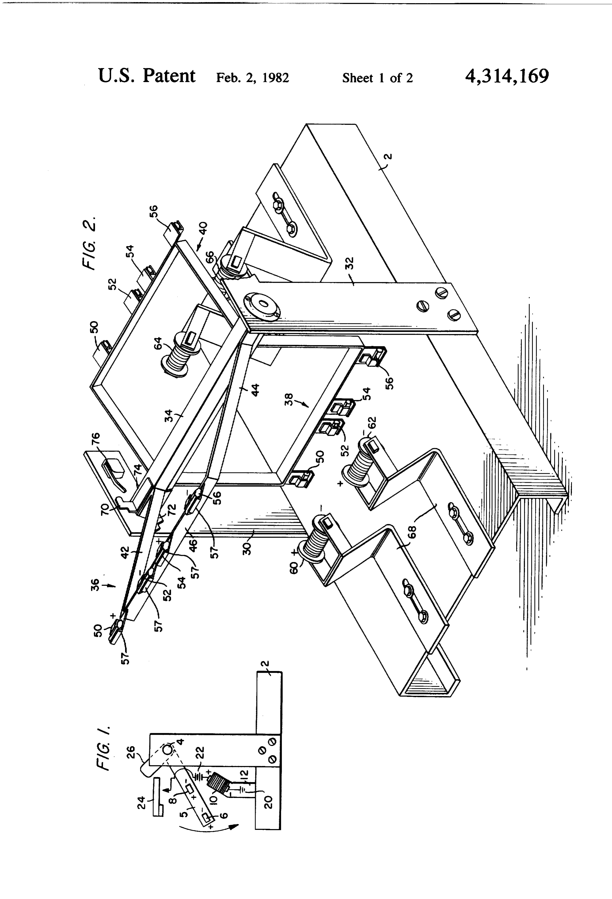
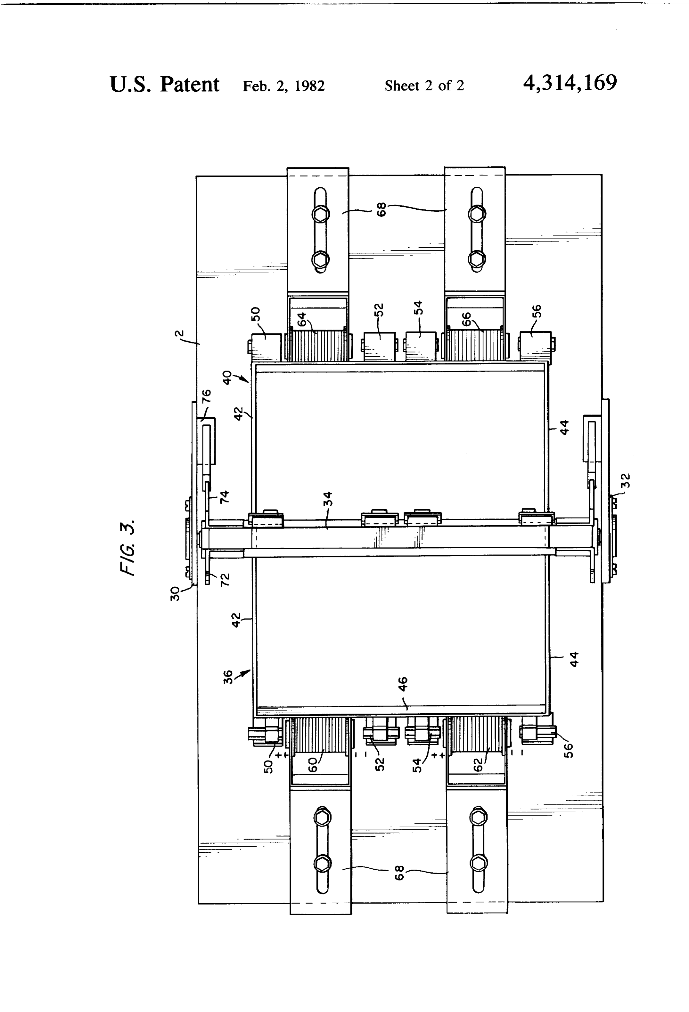
FIG. 1 is a diagrammatic view of a machine accord with respect to the base and is made of non-magnetic ing to the invention, showing the circuit for energizing material. The polarity of the poles of each coil is shown each electromagnetic coil; in FIG. 2.
Page 2drawing sheetscan →
Page 3drawing sheetscan →
Page 4scan →
120. Each bracket comprises spaced radial arms 42, 44
MAGNETIC MOTOR and transverse arm 46 which connects the outer ends of the two radial arms and is parallel to the shaft. Two
SUMMARY OF THE INVENTION pairs of permanent magnets 50, 52 and 54 and 56 are The disclosure is of an electromagnetic motor in 5 connected to each transverse arm 46, and each magnet which a plurality of electromagnetic coils are posi is supported on the arm by a bracket 57 formed of non tioned adjacent the shaft and a plurality of pairs of magnetic material. The spacing of the magnets of each permanent magnets are mounted on the shaft, each pair pair and the positions of their poles will be described. being positioned to pass successively past a coil with a O Two pairs of electromagnetic coils 60, 62 and 64, 66 pole of each permanent magnet adjacent the pole of the are mounted on the upper surface of base 2 at opposite same polarity of the coil, each coil being energized to sides of the shaft 4, and in the disclosed embodiment the produce a magnetic field during movement of a pair of axes of all of the coils are parallel to the shaft, and the permanent magnets past the coil. axes of the coils of each pair are aligned. A suitable DESCRIPTION OF THE DRAWINGS bracket 68 is provided for supporting each coil for ad 5 justment toward and away from the shaft and vertically
FIG. 1 is a diagrammatic view of a machine accord with respect to the base and is made of non-magnetic ing to the invention, showing the circuit for energizing material. The polarity of the poles of each coil is shown each electromagnetic coil; in FIG. 2.
FIG. 2 is a perspective view of a preferred embodi The permanent magnets of each pair of such magnets ment of the machine, and are so positioned on their supporting bracket that as the FIG. 3 is a top elevational view of the machine of assembly of shaft, brackets and permanent magnets FIG. 2. revolves the poles of the permanent magnets of each DESCRIPTION OF THE INVENTION pair successively pass closely to the poles of the electro magnetic coils. Thus, the poles of the permanent mag
In the part-elevational and part-schematic view of 25 nets 50, 52 successively pass the poles of coils 60 and 64 FIG. 1 of the drawings there is illustrated the mode of the poles of permanent magnets 54, 56 successfively operation of a machine according to the invention. The pass the poles of coils 62 and 66.
machine comprises a base 2 supporting a shaft 4 for In accordance with the invention the poles of the rotary movement. An arm 5 is mounted on the shaft and permanent magnets and those of the electromagnetic extends radially outwardly from it and adjacent its 30 coils are so positioned that poles of the same polarity are outer end carries two permanent magnets 6, 8 each adjacent as the permanent having positive and negative poles as indicated in the netic coils. Thus, positive magnets poles are pass the electromag adjacent in passing drawing. An electromagnetic coil 10 is mounted on the and negative poles are adjacent, and this relation is base 2 by bracket 12 in such a position that the poles of disclosed in the drawings.
the permanent magnets will pass closely adjacent the 35 poles of the coil as the shaft 4 and arm 5 are rotated, the In further accordance with the invention, and as arrangement being such that poles of like polarity of the described in connection with FIG. 1, each electromag permanent magnet and coil will be adjacent when the netic coil is energized by direct current during the short passage occurs, as shown in FIG. 1, interval while the permanent magnets are passing it. Means are provided by the invention for energizing The circuitry and switch means for effecting this are the coil 10 to produce a magnetic field about it as the disclosed in FIG. 1 and described in connection with poles of the permanent magnet pass the poles of the coil. that figure and need not be repeated in connection with In the disclosed form of the invention such means com FIGS. 2 and 3. However, in the embodiment disclosed prise an electric circuit including ground at 20 con in those figures three radial brackets are carried by the nected to one terminal of coil 10, a source of energy 22, 45 shaft, and therefore each coil must be energized three which may be a battery of wall plug, a normally open times during a complete rotation of the rotary assembly. switch 24, and can means 26 carried by shaft 4 for Therefore, in the disclosed embodiment, three cams 70, closing the switch when the poles of the permanent 72, 74 are mounted on each end of shaft 34 and are magnet are adjacent the coil in the rotary movement of angularly spaced equally to the spacing of the three the shaft 4 and arm 5. 50 brackets which support the permanent magnets, i.e. It will be understood from this disclosure of the basic approximately 120. A switch 76 is carried by bracket principle of operation of the invention that as the per 30 in position to be operated by the cams as the shaft manent magnets pass the coil direct current electric and cams are rotated, and operation of the switch com energy is momentarily supplied to the coil, charging it pletes the circuit energizing coil 60 or 64 as the perma and creating a magnetic field about it, the polarity of 55 nent magnets 50, 52 pass one or the other of those coils. which is such that the adjacent poles of the fields of the Three similar additional cams are mounted on the other permanent magnet and the coil are of the same polarity, end of shaft 34 and operate a second switch during thus producing mutually repulsive forces having a pro rotation of the shaft to energize coil 62 or coil 66 when pulsive effect on arm 5 and the rotary system of which the permanent magnets 54, 56 pass the ends of one or it forms a part, causing the shaft to rotate. 60 the other of these coils. It will be understood that these A preferred embodiment of a machine according to latter cams and switches are exactly similar to cams 70, the invention utilizing the principle illustrated in FIG. 1 72, 74 and switch 76 and operate in the same manner, is disclosed in FIGS. 2 and 3 of the drawings. This and are shown in FIG. 3.
machine comprises a base 2 having upright standards I have found that best results are obtained if energiza 30, 32 which support a shaft 34 for rotary motion. A 65 tion of any one of the electromagnetic coils is continued plurality of rectangular open brackets 36, 38, 40 extend only while the pair of permanent magnets which coop radially outwardly from the shaft and are equidistantly erates with the coil is moving through an arc of approxi spaced about it, adjacent brackets being separated by mately 20. The inertia of the rotating assembly contin 5 ues its motion until a pair of permanent magnets next mounted on the brackets being circumferentially reaches a coil. It will also be observed that by mounting and radially aligned about the shaft, the permanent magnets substantially outwardly of the e. a plurality of electromagnetic coils mounted on the shaft the repulsive forces created by the reaction of the base in surrounding relation to the shaft with the like poles of the permanent magnets and electromag 5 axis of each coil parallel to the shaft, netic coils as they pass operates through the leverage of f. the permanent magnets of each pair and the electro the arms 42, 44 of each of the brackets 36, 38, 40 thus magnetic coils being so constructed and positioned increasing the force exerted on the shaft and producing that on rotation of the shaft the permanent magnets a smoother operation.
I claim: O of each pair pass in close proximity to the ends of 1. An electromagnetic motor comprising: each electromagnetic coil, a. a fixed base, g. means normally maintaining each coil deemergized, b. an elongated shaft rotatably mounted on the base, and
C. a plurality of brackets mounted in spaced circum h. means for so energizing each coil during passage ferential relation on the shaft, each bracket com 5 by it of a pair of permanent magnets that each pole prising radial arms of the same length mounted in of each pair of permanent magnets passes adjacent spaced relation on the shaft, and a transverse arm a pole of the same polarity as it passes each coil. mounted on the ends of the radial arms and parallel 2. A motor according to claim 1, in which each coil is to and spaced from the shaft, energized during movement of each pair of permanent d. a pair of permanent magnets mounted on each 20 magnets passed it through an arc of approximately 20 transverse arm of each bracket in spaced relation degrees.
along the transverse arm, with the magnets k k k k k
Provenance
- Collection
- Patents citing this work
- Pages
- 5
- Method
- pdftotext (the PDF's own text layer) + pdftoppm 300dpi page scans
- Patent office record
- patents.google.com →
- Source
- Google Patents citing-documents table
- Assignee
- Electro-Magnetic Motors Inc.
- Published
- 1982-02-02
- Transcribed from
- patentimages.storage.googleapis.com →