

patent · US3914090A
Method and furnace apparatus
21 October 1975
Text
Page 1bibliographic recordscan →
United States Patent (19)
Pfeffere
METHOD AND FURNACE APPARATUS
75 Inventor: William C. Pfefferle, Middletown,
Assignee: Engelhard Minerals & Chemicals Corporation, Murray Hill, N.J.
Related U.S. Application Data 63 Continuation-in-part of Ser. No. 142,939, May 13, 1971, abandoned, Continuation-in-part of Ser. No.
Continuation-in-part of Ser. No. 252,916, May 12, 1972, abandoned, Continuation-in-part of Ser. No.
52 U.S. Cl...................................... 431/9; 431/115 51 Int. Cl............................................ F23M 3100
UNITED STATES PATENTS
3,729,285 4/1973 Schwedersky.......................... 431/8
3,868,211 2/1975 LaHaye................................. 431/10
Primary Examiner-Edward G. Favors
Carbonaceous fuel is thermally combusted with an amount of air substantially less than that needed for complete combustion to carbon dioxide and water of all the combustible components in the fuel to produce a gaseous effluent containing a substantial proportion of carbon monoxide but little or no nitrogen oxides. Additional carbonaceous fuel is mixed with air, and at least a portion of this mixture is passed into the pres ence of a solid oxidation catalyst for adiabatic com bustion at a temperature above the instantaneous auto-ignition temperature of the mixture but below nitrogen-oxide-forming temperatures. The first gase ous effluent and the gases exiting from the catalyst are mixed and thermal combustion takes place in this mix ture to produce a completely combusted final combus tion effluent which is low in atmospheric pollutants, particularly nitrogen oxides.
46 Claims, 5 Drawing Figures
Drawings
Page 2drawing sheetscan →
Page 3drawing sheetscan →
Page 4scan →
METHOD AND FURNACE APPARATUS mal combustion stage substantially limit the formation of nitrogen oxides. Heat is withdrawn from the first
This application is a continuation-in-part of prior stage effluent and that effluent is then mixed with addi abandoned applications, Ser. No. 142,939, filed May tional air and thermally combusted in a subsequent 13, 1971, Ser. No. 164,718, filed July 21, 1971, and thermal combustion stage or stages. The additional air Ser. No. 252,916, filed May 12, 1972, and copending is sufficient to make up the deficiency of air supplied application Ser. No. 358,411, filed May 8, 1973. to the first thermal combustion stage so that in the sub
Background of the invention
sequent stage or stages all of the carbon monoxide in the first stage effluent is completely oxidized to carbon
This invention relates to a furnace method and appa 10 dioxide and any unburned or partially burned fuel in ratus for burning carbonaceous fuel to produce energy that effluent is completely oxidized to carbon dioxide in the form of heat. and water. Although conditions in at least the last of One of the most important problems encountered in the combustion stages must be sufficiently oxidizing to designing and operating furnaces is to control the insure complete combustion of the fuel, less nitrogen amounts of nitrogen oxides in the furnace exhaust 15 oxides are produced than would be produced in a sin gases, since nitrogen oxides are an extremely serious air gle-stage combustion system.
pollution problem. Substantial amounts of nitrogen ox Although the foregoing systems decrease the forma ides inevitably form when fuel and at least a stoichio tion of nitrogen oxides, these systems do not eliminate metric amount of air are combusted attemperatures in formation of nitrogen oxides and are, in addition, typi excess of about 3300°F. As used herein and in the ap 20 cally more difficult to operate and control. For exam pended claims, the term air means any gas or combina ple, in these systems it is frequently more difficult to tion of gases including oxygen available for combustion achieve efficient thermal combustion reactions and reactions, and the term stoichiometric amount of air avoid formation of substantial amounts of incomplete means an amount of air which is theoretically sufficient combustion products such as carbon monoxide and un for complete oxidation of all the combustible compo 25 combusted hydrocarbons without the production of nents in a given amount of fuel (e.g., to carbon dioxide high concentrations of nitrogen oxides. Although only and water). The term carbonaceous fuel means any an insignificant amount of fuel value may be lost as a fuel in which a substantial proportion of the fuel value result of this incomplete combustion, the incomplete is elemental carbon or carbon compounds containing combustion products are another serious air pollution carbon in combustible combination with other ele 30 problem. To insure complete combustion of the fuel ments such as hydrogen. and for general ease of operation, furnaces are there One way of reducing the amounts of nitrogen oxides fore frequently operated with substantially more air formed in a furnace is to lower the temperature in the than is theoretically sufficient for complete combustion furnace by mixing the fuel with an increased volume of 35 of the fuel supplied to the furnace. As mentioned effectively inert gas to produce a diluted fuel-air mix above, however, excess air decreases thermal effi ture. For reasons of thermal efficiency, it is almost al ciency. In addition, there are practical limits on how far ways preferable to use no more air in the furnace than temperatures can be lowered in a conventional two is required for complete combustion of the fuel (i.e., as stage combustion furnace and still maintain stable com close to the stoichiometric amount of air as possible). 40 bustion. This in turn limits the achievable reduction in Any air in excess of the stoichiometric amount must be nitrogen oxide formation.
heated, generally from ambient temperature, to the In view of the foregoing, it is an object of this inven temperature in the furnace and then exhausted into the tion to reduce the amount of atmospheric pollutants atmosphere again, carrying with it whatever heat can produced by furnaces burning carbonaceous fuels to not be recovered for a useful purpose. The preferred 45 produce thermal energy.
source of inert gases for mixing with the fuel and air to It is another object of this invention to increase the lower combustion temperature are the final combus thermal efficiency of furnaces burning carbonaceous tion effluent or stack gases of the furnace. These gases fuel to produce thermal energy. are warmer than ambient air, but substantially cooler It is yet another object of this invention to increase than the gases leaving the combustion zone. Accord 50 the efficiency of combustion in furnaces burning carbo ingly, a portion of the final combustion effluent gases naceous fuel to produce thermal energy, particularly in of the furnace may be recycled to dilute the fuel and air combination with low production of nitrogen oxides. supplied to the furnace to lower combustion tempera In copending application Ser. No. 358,411, filed May tures in the furnace and help control the formation of 8, 1973, and incorporated herein by reference, there is nitrogen oxides. 55 disclosed the discovery of catalytically-supported, ther
Another way in which the formation of nitrogen ox mal combustion. According to this method, carbona ides can be controlled is by conducting the combustion ceous fuels can be combusted very efficiently at tem of the fuel in two or more successive stages. In the first peratures between about 1700 and 3200°F, for exam stage, a mixture of fuel and an amount of air substan ple, without the formation of substantial amounts of tially less than the amount needed for complete com 60 carbon monoxide or nitrogen oxides by a process desig bustion of the fuel (i.e., a non-stoichiometric mixture nated catalytically-supported, thermal combustion. To on the fuel-rich side) is thermally combusted to pro summarize briefly what is discussed in greater detail in duce a gaseous effluent containing a substantial pro application Ser. No. 358,411, in conventional thermal portion of carbon monoxide. This effluent may also combustion of carbonaceous fuels, a flammable mix contain some uncombusted or partially combusted 65 ture of fuel and air or fuel, air, and inert gases is con fuel. The temperature of this combustion (which is low tacted with an ignition source (e.g., a spark) to ignite relative to the stoichiometric combustion temperature) the mixture. Once ignited, the mixture continues to and particularly the insufficiency of air in this first ther burn without further support from the ignition source.
Page 5scan →
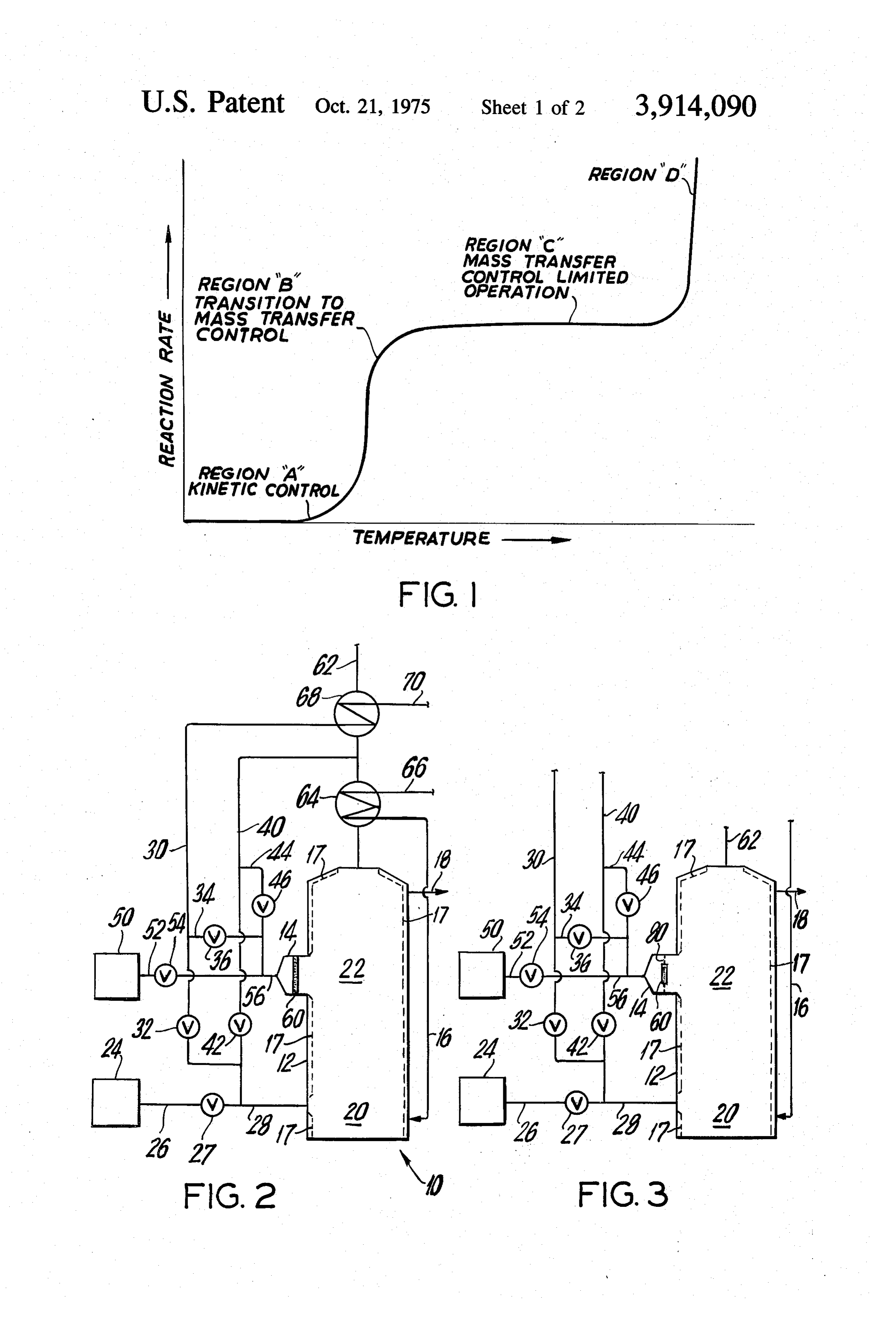
Flammable mixtures of carbonaceous fuels normally in the case of gas turbine engines, the catalytic reactor burn at relatively high temperatures (i.e., normally well might very well be larger than the engine itself. above 3300°F). At these temperatures substantial As described in application Ser. No. 358,411, it has amounts of nitrogen oxides inevitably form if nitrogen been discovered that it is possible to achieve essentially is present, as is always the case when air is the source 5 adiabatic combustion in the presence of a catalyst at a of oxygen for the combustion reaction. Mixtures of fuel reaction rate many times greater than the mass transfer and air or fuel, air, and inert gases which would theo limited rate. In particular, it has been found that if the retically burn at temperatures below about 3300F are operating temperature of the catalyst is increased sub too fuel-lean to support a stable flame and therefore stantially into the mass transfer limited zone, the reac cannot be satisfactorily burned in a conventional ther O tion rate again begins to increase rapidly with tempera mal combustion system. ture (region D in the graph of FIG, 1). This is in appar In conventional catalytic combustion, on the other ent contradiction of the laws of mass transfer kinetics hand, the fuel is burned at relatively low temperatures in catalytic reactions. The phenomenon may be ex (typically in the range of from a few hundred degrees plained by the fact that the temperature of the catalyst Fahrenheit to approximately 1400°F) and little or no 15 surface and the gas layer near the catalyst surface are nitrogen oxides are formed. Prior to the invention de above the instantaneous auto-ignition temperature of scribed in application Ser. No. 358,411, however, cata the mixture of fuel, air, and any inert gases (defined lytic combustion was regarded as having limited value herein and in application Ser. No. 358,411 to mean the as a source of thermal energy. In the first place, con temperature at which the ignition lag of the mixture en ventional catalytic combustion proceeds relatively 20 tering the catalyst is small compared to the residence slowly so that impractically large amounts of catalyst time of the mixture in the combustion zone) and at a would be required to produce enough oxidation gases temperature at which thermal combustion occurs at a to drive a turbine or to consume the large amounts of rate higher than the catalytic combustion rate. The fuel fuel required in most large furnace applications. In the molecules entering this layer burn spontaneously with second place, the reaction temperatures normally asso 25 out transport to the catalyst surface. As combustion ciated with conventional catalytic combustion are too progresses and the temperature increases, it is believed low for efficient transfer of heat for many purposes, for that the layer in which thermal combustion occurs be example, transfer of heat to water in a steam boiler. comes deeper. Ultimately, substantially all of the gas in Typically, catalytic combustion is also relatively ineffi 30 the catalytic region is raised to a temperature at which cient, so that large amounts of carbon monoxide are thermal combustion occurs in virtually the entire gas. produced or left uncombusted unless low space veloci stream rather than just near the surface of the catalyst. ties in the catalyst are employed. Once this stage is reached within the catalyst, the ther Catalytic combustion reactions follow the course of mal reaction appears to continue even without further the graph shown in FIG. 1 of the accompanying draw 35 contact of the gas with the catalyst. ing, to the extent of regions A through C in that Figure. The foregoing is offered as a possible explanation This graph is a plot of reaction rate as a function of only and is not to be construed as in any way limiting temperature for a given catalyst and set of reaction the present invention.
conditions. At relatively low temperatures (i.e., in re Among the unique advantages of the above gion A of FIG. 1) the catalytic reaction rate increases 40 described combustion in the presence of a catalyst is exponentially with temperature. As the temperature is the fact that mixtures of fuel and air which are too fuel raised further, the reaction rate enters a transition zone lean for ordinary thermal combustion can be burned (region B in the graph of FIG. 1) in which the rate at efficiently. Since the temperature of combustion for a which the fuel and oxygen are being transferred to the given fuel at any set of conditions (e.g., initial tempera catalytic surface begins to limit further increases in the ture and, to a lesser extent, pressure) is dependent reaction rate. As the temperature is raised still further, 45. largely on the proportions of fuel, of oxygen available the reaction rate enters a so-called mass transfer lim for combustion, and of inert gases in the mixture to be ited zone (region C in the graph of FIG. 1) in which the burned, it becomes practical to burn mixtures which reactants cannot be transferred to the catalytic surface are characterized by much lower flame temperatures fast enough to keep up with the catalytic surface reac 50 than those of the customary combustible mixtures. In tion and the reaction rate levels off regardless of fur particular, carbonaceous fuels can be burned very effi ther temperature increases. In the mass transfer limited ciently and at thermal reaction rates at temperatures in zone, the reaction rate cannot be increased by increas the range from about 1700 to about 3200°F. At these ing the activity of the catalyst because catalytic activity temperatures very little nitrogen oxides are formed, if is not determinative of the reaction rate. Prior to the 55 any, and indeed the reaction may be such as actually to invention described in application Ser. No. 358,41 1, decrease the amounts of nitrogen oxides present in the the only apparent way to increase the reaction rate in gases supplied to the reaction. In addition, because the the mass transfer limited zone was to increase the mass combustion as above described is stable over a wide transfer rate. However, this requires an increase in the range of mixtures, it is possible to selector control re pressure drop across the catalyst and consequently a 60 action temperature over a correspondingly wide range. substantial loss of energy. Sufficient pressure drop may by selecting or controlling the realitive proportions of not even be available to provide the desired reaction the gases in the mixture.
rate. Of course, more mass transfer can be effected, The combustion method, as described in the copend and hence more energy can always be produced, by in ing application Ser. No. 358,411, involves essentially creasing the amount of catalyst surface. In many appli 65 adiabatic combustion of a mixture of fuel and air or cations, however, this results in catalyst configurations fuel, air, and inert gases in the presence of a solid oxi of such size and complexity that the cost is prohibitive dation catalyst operating at a temperature substantially and the body of the catalyst is unwieldy. For example, above the instantaneous auto-ignition temperature of
Page 6scan →
S 6 the mixture, but below a temperature which would re ond effluent gases. A portion of the second fuel-air sult in any substantial formation of oxides of nitrogen mixture may be allowed to by-pass the catalyst and under the conditions existing in the catalyst. The in enter the second thermal combustion zone directly for stantaneous auto-ignition temperature of the mixture is thermal combustion with the other gases downstream defined above. Essentially adiabatic combustion means of the catalyst. Additional heat is withdrawn from this in this case that the operating temperature of the cata second thermal combustion zone for the purpose for lyst does not differ by more than about 300°F, more which the furnace is being operated (e.g., to generate typically no more than about 150°F, from the adiabatic steam). When the final combustion effluent gases are flame temperature of the mixture due to heat losses too cool for further efficient transfer of heat for the from the catalyst. 10 principal purpose of furnace operation, additional heat
Summary of the invention
may be recovered from these gases by conducting them to one or more heat exchanges, for example, for pre
In accordance with the principles of this invention, heating water returning to the furnace for conversion carbonaceous fuel in any form is thermally combusted to steam and for preheating the air mixed with the fuel in the first thermal combustion zone or stage of a fur 15 prior to combustion. Some of these final combustion nace, utilizing a first mixture formed of the fuel and an effluent gases may be recycled in the furnace by mixing amount of air substantially less than the amount needed them with the first fuel and air mixture, supplied to the for complete combustion to carbon dioxide and water first thermal combustion stage, or with the second mix of all the combustible components in the fuel, to pro ture passed in the presence of the catalyst, or with both duce a gaseous first effluent containing a substantial mixtures. The remaining final combustion effluent proportion of carbon monoxide. This effluent may also gases may be exhausted into the atmosphere. contain some uncombusted or partially combusted fuel Advantageously, as much as possible of the total (e.g., some unburned or partially burned hydrocar amount of fuel supplied to the furnace is fed to the fur bons). Heat ordinarily is withdrawn from the first ther nace by way of the second mixture for combustion in mal combustion zone for whatever purpose the furnace 25 the presence of the catalyst. This combustion and the is being operated (e.g., to generate steam in boiler thermal combustion of the first and second effluents tubes in the furnace), thereby cooling the first effluent. downstream of the catalyst are both very stable and ef If it is desired to retain the heat of this first stage com ficient, even at the low temperatures which substan bustion in the effluent, it is possible to carry out this tially prevent the formation of nitrogen oxides. Sub combustion adiabatically while adding inert quench gas 30 stantially complete combustion of all the fuel supplied to limit the temperature rise at this stage. to the furnace can therefore be achieved with only A second mixture is also formed of additional carbo slightly more air than is theoretically sufficient for such naceous fuel and air, such that this second mixture can complete combustion, even while the formation of ni be conducted through or past a catalyst and at least 35 trogen oxides is substantially prevented. The thermal partially combusted in the presence thereof. The efficiency of furnaces constructed in accordance with amount of air mixed with the additional fuel is prefera the principles of this invention is therefore high, while bly just sufficient to oxidize to carbon dioxide and at the same time emissions of air pollutants (particu water all the additional fuel and all combustible com larly carbon monoxide and nitrogen oxides) are low. ponents remaining in the gaseous first effluent; al 40 Further features of the invention, its nature and vari though less than this amount of air may be mixed with ous advantages, will be more apparent from the accom the additional fuel at this point and the remainder then panying drawing and the following detailed description supplied directly to the second thermal combustion of the invention.
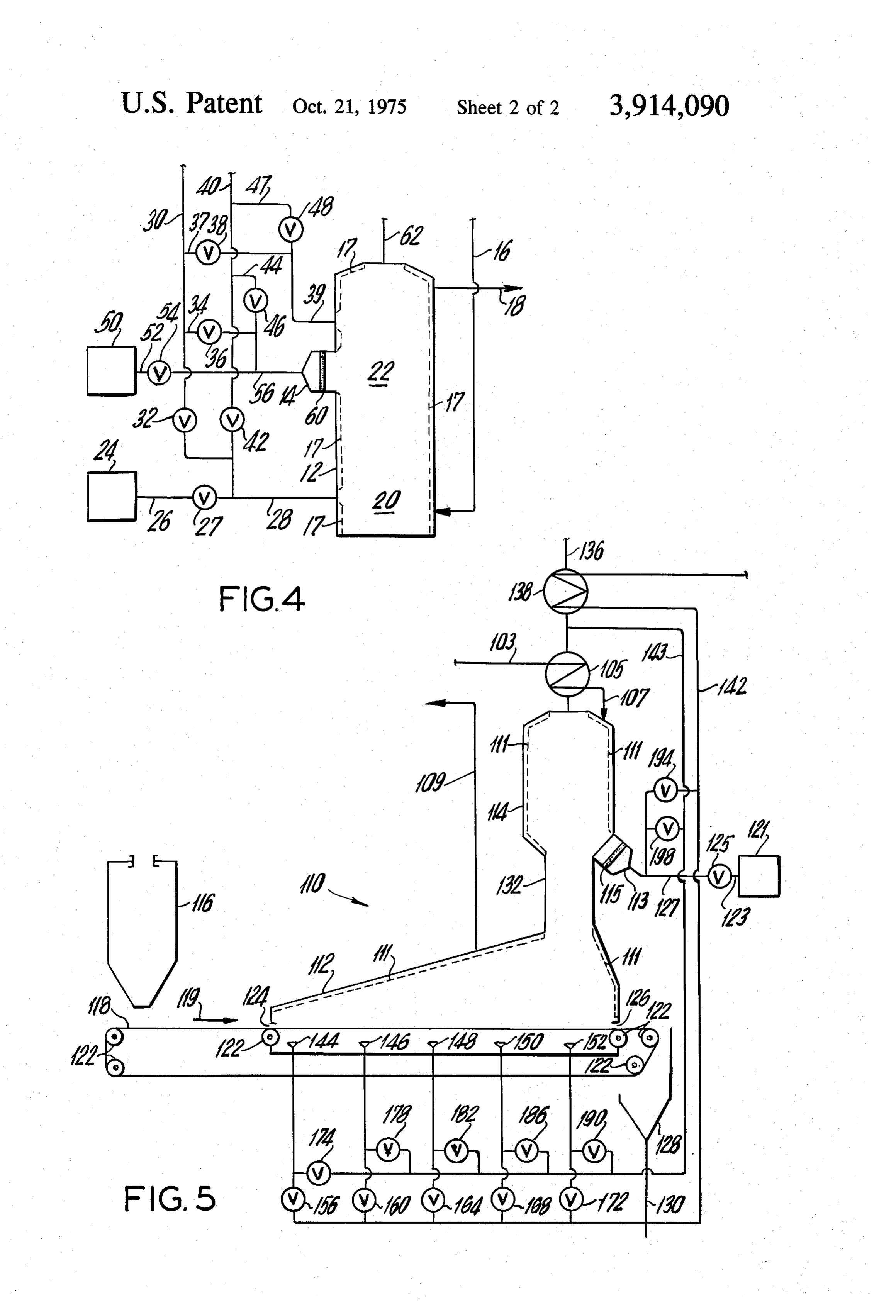
state described below. The additional fuel may be the BRIEF DESCRIPTION OF THE DRAWING same as that supplied to the furnace for thermal com 45 bustion in the first combustion zone, or it may be a FIG. 1 is, as described above, a graph of combustion completely different carbonaceous fuel. At least a por reaction rate as a function of temperature for combus tion of this second mixture is fed to a solid oxidation tion in the presence of a solid oxidation catalyst; catalyst where it is subjected to essentially adiabatic FIG. 2 is a simplified schematic drawing of a furnace combustion in the presence of the catalyst operating at 50 constructed in accordance with the principles of this a temperature substantially above the instantaneous invention for burning atomized, vaporized, gaseous, or auto-ignition temperature of the mixture but below a gasified carbonaceous fuels;
temperature that would result in any substantial forma FIG. 3 is a simplified schematic drawing showing a tion of oxides of nitrogen, producing a second effluent. modification of the furnace of FIG. 2 in accordance Typically, the operating temperature of the catalyst is 55 with the principles of this invention; in the range from about 1700° to about 3200°F, prefer FIG. 4 is a simplified schematic drawing showing an ably from about 2000 to about 3000°F. Although there other modification of the furnace of FIG. 2 in accor may be a small amount of radiant or conductive heat dance with the principles of this invention; and transfer away from the catalyst, the combustion taking FIG. 5 is a simplified schematic drawing showing a place in the presence of the catalyst remains essentially 60 furnace constructed in accordance with the principles adiabatic, as stated above. of this invention for burning solid carbonaceous fuel in The first effluent and the second effluent, produced the first combustion stage and for combusting atom as just described, are mixed and thermally combusted ized, vaporized, gaseous, or gasified carbonaceous fuel in a second thermal combustion stage or zone down in the presence of a catalyst in the second combustion stream of the catalyst to produce a final combustion ef 65 stage.
fluent. Combustion in this second thermal combustion zone is induced and maintained by the temperature lev DETAILED DESCRIPTION OF THE INVENTION els resulting from the combination of the first and sec As shown in FIG. 2, a furnace 10 for burning atom 7 ized, vaporized, gaseous, or gasified carbonaceous fuel amount for that fuel. Lower percentages in this range includes a vertically disposed combustion housing 12, may be possible when the fuel supplied to zone 20 is and a catalyst-containing combustion housing 14 com carbon monoxide, methanol, and the like. In the case municating with an intermediate portion of combustion of fuels (e.g., vaporized or gaseous hydrocarbons) for housing 12. Although furnaces constructed in accor which soot formation is a more serious problem, the dance with the principles of this invention may be oper amount of air supplied to Zone 20 is preferably from ated to produce heat for practically any purpose, it will about 80 to 90% of the stoichiometric amount. The be assumed that the furnaces described herein are gaseous thermal combustion effluent typically contains being operated to produce heat for the generation of from about 5 to 30, preferably at least about 10, vol steam. Accordingly, water (which may be preheated as O ume percent carbon monoxide.
described below) is supplied to a system of boiler tubes The amount of recycle gases supplied to thermal represented schematically by broken lines 17 in ther combustion zone 20 may be governed by a number of mal combustion housing 12 by way of line 16 and, after considerations. For example, it may be desirable to conversion to steam, exits from that boiler tube system supply these gases to achieve a predetermined combus by way of line 18. Of course, all the various parts of 15 tion temperature in thermal combustion zone 20 or to boiler tube system 17 are interconnected. increase the volume of gases flowing through the fur Combustion housing 12 includes a first thermal com nace to improve heat transfer from the thermal com bustion zone 20 near the bottom of housing 12, this bustion zones of the furnace. In any event, the relative portion of housing 12 serving as means for thermally proportions of fuel, air, and recycle gases supplied to combusting a first mixture of fuel and air, and a second thermal combustion zone 20 must always be such as to thermal combustion zone 22 above zone 20 and adja provide a flammable mixture for thermal combustion in cent catalyst-containing combustion housing 14. Car zone 20.
bonaceous fuel from fuel supply 24 is supplied to the Although in the particular embodiment shown in first thermal combustion zone by way of line 26 having FIG. 2, air from air supply line 30 and recycle gases valve 27 and line 28. In line 28, the fuel is mixed with 25 from recycle gas supply line 40 are mixed together preheated air supplied by way of air supply line 30 hav prior to mixing with fuel in line 28, it will be understood ing valve 32 and, if desired, with inert gases (i.e., a re that these three components can be mixed together in cycled portion of the final combustion effluent of the any order or simultaneously as desired. Similarly, al furnace) supplied by way of recycle gas supply line 40 though all three of these components are shown as having valve 42, forming the aforesaid first mixture. If 30 mixed together prior to being fed to furnace 10, it will the carbonaceous fuel is initially solid, fuel supply 24 be understood that any one or all three components must include apparatus for gasifying the fuel for pas can be fed to furnace 10 separately and mixed with the sage to the furnace via line 26. If the fuel is initially liq other components in thermal combustion zone 20. For uid, line 28, or line 40 if desired, may include apparatus example, if the fuel from fuel supply 24 is a liquid fuel, for spraying the fuel into the preheated air and/or hot 35 it may be desirable to vaporize it in thermal combustion recycle gases to atomize or vaporize the fuel. Examples zone 20 by spraying it directly into housing 12. Air and of carbonaceous fuels which can be burned in the fur recycle gases can then be supplied to thermal combus naces of this invention are any solid carbonaceous fuel tion zone 20 by separate gas distribution means. If fuel (e.g., coal, coke, charcoal, etc.) which can be gasified; is mixed with air prior to being fed to furnace 10, con any normally liquid hydrocarbon (e.g., naphtha, kero 40 ditions in the mixture are preferably such that little or sene, diesel oil, fuel and heating oils, certain residual no thermal combustion takes place before the mixture and non-distilled mineral oils, etc.) which can be at enters housing 12.
least partially vaporized; alkanols such as methanol, Returning to the embodiment shown specifically in ethanol, and other fuels containing combined oxygen FIG. 2, in first thermal combustion zone 20, the mix such as carbon monoxide; and practically any normally 45 ture of fuel, air, and recycle gases supplied to the fur gaseous hydrocarbon such as methane, ethane, pro nace by way of line 28 is thermally combusted. Con pane, and other low molecular weight hydrocarbons. ventional apparatus (not shown) is provided for ignit The amount of air mixed with the fuel supplied to ing the mixture in housing 12 and for insuring that thermal combustion zone 20 is substantially less than flame is continuous once it has been established. Heat, the amount needed for complete combustion of all the is withdrawn from thermal combustion zone 20 to gen combustible components in the fuel to carbon dioxide erate steam in boiler tubes 17, thereby cooling the ef and water. Thermal combustion in zone 20 therefore fluent gases as they rise in housing 12 toward second takes place under relatively reducing conditions, as is thermal combustion zone 22. s desirable to prevent the formation of excessive 55 Although only one inlet for the mixture of fuel, air, amounts of nitrogen oxides, and the gaseous effluent of and recycle gases supplied to thermal combustion zone the thermal combustion contains a substantial propor 20 is shown in FIG. 2, it will be understood that any tion of carbon monoxide. The gaseous thermal com number and arrangement of inlets can be used to ade bustion effluent may also contain some uncombusted quately distribute the mixture in the furnace. For exam or partially combusted fuel (e.g., some unburned or 60 ple, the furnace may be a tangentially or corner fired partially burned hydrocarbons). On the other hand, the furnace in which the mixture is fed to the furnace at amount of air supplied to thermal combustion zone 20 several points around the periphery of housing 12 with must be at least sufficient to provide a flammable mix a tangential component of velocity to produce a swirl ture in zone 20 and is also preferably sufficient to pre ing fireball in the furnace.
vent any substantial formation of soot, Depending on 65 In addition to the fuel from fuel supply 24 being ther the kind and quantity of fuel supplied to thermal com mally combusted in first thermal combustion zone 20 bustion zone 20, the amount of air supplied to Zone 20 as described above, additional carbonaceous fuel sup may vary from about 50 to 90% of the stoichiometric plied from fuel supply 50 by way of line 52 having valve
Page 8scan →
9 O 54 is mixed with air supplied from line 30 by way of line mixing with fuel in line 56, it will be understood that 34 having valve 36 and, if desired, with recycle gases these components of the second mixture may be mixed supplied from line 40 by way of line 44 having valve 46 together in any order or simultaneously as desired. Fur to produce a catalytically combustible second mixture thermore, although all three of these components are containing fuel and air in line 56. The aforesaid fuel 5 shown being mixed together prior to being fed to hous supply, lines, and valves thus constitute convenient ing 14, it will be understood that any one or all three means for forming the second mixture. The recycle of these components can be fed to housing 14 sepa gases are substantially inert, but may have a small com rately and mixed with the others in housing 14 prior to ponent of unconsumed combustion oxygen. This mix passage through or in the presence of catalyst 60. The ture is fed to the combustion housing 14 wherein at O second mixture including fuel and air passing to cata least a portion of the second mixture is combusted in lyst 60 is such that little or no combustion occurs in the presence of solid oxidation catalyst 60 disposed housing 14 at temperatures which would result in any across a portion of housing 14 to produce a second ef substantial formation of nitrogen oxides. fluent. As mentioned above, in the combustion in the pres Any of the fuels mentioned above as suitable for 15 ence of a catalyst taking place in housing 14, at least a combustion in thermal combustion zone 20 are also portion of the second mixture supplied by way of line suitable for combustion in the catalyst-containing com 56 is combusted under essentially adiabatic conditions bustion housing 14. Since at least a portion of the fuel in the presence of solid oxidation catalyst 60 operating in the second mixture from fuel supply 50 is to be com at a temperature substantially above the instantaneous busted in the presence of catalyst 60, at least a portion auto-ignition temperature of the mixture but below a of the fuel must be in catalytically combustible form temperature at which polluting amounts of nitrogen ox (such as atomized, vaporized, gaseous, or gasified) by ides form. Typically, the operating temperature of the the time it reaches the catalyst. Accordingly, if the fuel catalyst is in the range from about 1700 to about supplied by fuel supply 50 is initially solid, fuel supply 3200°F, preferably from about 2000 to about 3000°F. 50 must include apparatus for gasifying the fuel for pas 25 At least the portion of the combustion housing 14 sur sage to the combustion housing 14 via line 52. If the rounding catalyst 60 and any portion of housing 14 fuel supplied by fuel supply 50 is initially liquid, line 56 downstream of the catalyst must be constructed to may include apparatus for spraying the fuel into the withstand these combustion temperatures. preheated air and/or hot recycle gases respectively sup The operating temperature of catalyst 60 is deter plied by way of lines 34 and 44 to atomize and/or at 30 mined by the adiabatic flame temperature of the mix least partially vaporize the fuel. Even if some of the liq ture being combusted in the presence of the catalyst. uid fuel reaches catalyst 60 in liquid form, however, ad Typically, the reactive surface of the catalyst is at or ditional vaporization occurs when the fuel contacts the near the adiabatic flame temperature of the mixture hot catalyst. Although separate fuel supplies 24 and 50 35 (i.e., the operating temperature of the catalyst does not are shown in FIG. 2, it will be understood that the fuel deviate more than about 300°F, more typically no more fed to the first thermal combustion zone 20 and to the than about 150°F, from the adiabatic flame tempera combustion housing 14 may be the same or different ture of the mixture due to heat transfer from the cata fuel as desired, and if the fuel is the same, it may be ulti lyst), and combustion of the second mixture thus takes mately derived from one source. For example, the fuel place at or near that adiabatic flame temperature. For supplied by fuel supply 24 may be fuel oil and the fuel 40 a given fuel at any set of conditions (e.g., initial temper supplied by fuel supply 50 may be natural gas, or the ature and, to a lesser extent, pressure), the adiabatic fuel supplied by both fuel supplies may be natural gas. flame temperature of a mixture of that fuel, air, and re The fuel supplied by either or both fuel supplies may cycle gases is a function of the relative proportions of fluctuate seasonally, depending on the availability of 45 fuel, air, and recycle gases in the mixture. Since the rel certain fuels. ative proportions of fuel and air in the mixture supplied The amount of air supplied by way of line 34 for mix to the combustion housing 14 are governed by the con ing with the fuel from fuel supply 50 is preferably just siderations of stoichiometry and thermal efficiency dis sufficient for complete combustion to carbon dioxide cussed above (i.e., the need to provide at least enough and water of all the fuel from fuel supply 50 and of all air for complete combustion of the fuel and thermal the uncombusted and incompletely combusted values 50 combustion effluent but not substantially more than remaining in the first effluent, leaving combustion zone that amount), the desired adiabatic flame temperature, 20. Thus, the total amount of air supplied to the fur and therefore the desired temperature of combustion in nace (i.e., to both the first thermal combustion stage in the presence of the catalyst, is often achieved by adjust zone 20 and the catalyst-containing combustion stage 55 ing the amount of recycle gases in the mixture supplied in housing 14) is at least the stoichiometric amount for to the combustion housing 14 containing the catalyst. the total amount of fuel supplied to the furnace. More In order to initially establish combustion in catalyst over, in the interest of thermal efficiency, the total 60, housing 14 may include an ignitor (not shown) for amount of air supplied to the furnace is preferably no initially igniting the second mixture of fuel and air en more in excess of the stoichiometric amount than is ac 60 tering housing 14, thereby heating catalyst 60 to a tem tually necessary for substantially complete combustion perature which will sustain the desired combustion. of all the fuel supplied to the furnace. Recycle gases are Once these combustion temperatures have been supplied by way of line 44 in the amount needed to pro reached in the catalyst, the ignitor can be deactivated duce a final mixture in line 56 having a desired adia and pre-ignition of the fuel discontinued. During this batic flame temperature. 65 start-up operation, it may be necessary to alter the Although in the particular embodiment shown in amounts and relative proportions of fuel, air, and recy FIG. 2, air supplied by way of line 34 and recycle gases cle gases supplied by way of line 56 to insure flammable supplied by way of line 44 are mixed together prior to conditions in housing 14 prior to catalyst 60.
Page 9scan →
As illustrated, the combustion housing 14 is designed Since heat is being withdrawn from the gases in zone and catalyst 60 is located in housing 14 so that the sec 22, the adiabatic flame temperature of the gases being ond effluent gases, exiting from the combustion of the combusted is typically higher than the actual combus second mixture in housing 14, almost immediately tion temperature. Temperatures in zone 22 may be enter second thermal combustion zone 22 in housing controlled in a number of ways. For example, tempera 12 and begin to mix with the first effluent gases rising tures in zone 22 may be monitored (e.g., by thermo from combustion zone 20. It will be appreciated that, couples, not shown) and the information thus produced in an alternative mode of operation (not illustrated), may be used to control the amounts or proportions of heat may be withdrawn from the second effluent during fuel supplied to the furnace by way of lines 28 and 56. its passage from housing 14 to zone, 22. Oxidation of 10 Alternatively or in addition, the temperature informa the gases exiting from catalyst 60 may be substantially tion can be used to control the amounts or proportions complete, although it is usually preferable to have ther of air and/or recycle gases supplied to the furnace by mal combustion of the fuel supplied to catalyst 60 con way of lines 28 and 56 to adjust temperatures in zone. tinue downstream of the catalyst (i.e., in thermal com 22. In view of the number of operating parameters bustion zone. 22). This makes it possible to use less cat 15 which can be controlled, the system has a great deal of alyst and reduce the required pressure drop across the operating flexibility. Advantageously, the gases from catalyst. Although only one catalyst-containing com first thermal combustion zone 20 can be fed to second bustion housing 14 is shown in the simplified schematic thermal combustion zone 22 at substantially lower tem of FIG. 2, it will be understood that any number of simi peratures than would be possible in a conventional two lar combustion housings can be arrayed around the pe 20 stage furnace, since the extremely stable combustion in riphery of housing 12 in the vicinity of second thermal the presence of catalyst 60 is available to support ther combustion zone 22 to insure rapid and complete mix mal combustion in Zone 22 and insure complete com ing of the second effluent gases exiting from the com bustion of incompleted combusted materials in the first bustion catalysts and the first effluent gases from first effluent even though that effluent is relatively cool. In thermal combustion zone 20. The region of the furnace 25 a conventional system, there is relatively little flexibil wherein such first and second effluents come together, ity with regard to temperature of the first stage effluent along with the entirety of the combustion zone 22, thus since that effluent must be hot enough to support ther constitutes means for mixing and thermally combusting mal combustion in the second stage. In the systems of the first and second effluents downstream of the cata the present invention, considerably more heat can be lyst. 30 withdrawn from the first stage effluent to generate In second thermal combustion zone 22, the mixture steam and the resulting relatively low temperature of of gases from housing 14 and from first thermal com the first stage effluent permits control of temperatures bustion zone 20 accordingly is thermally combusted to in zone 22 to a value below which substantial formation produce a completely combusted final combustion ef. of nitrogen oxides occurs.
fluent. Accordingly, any uncombusted fuel in the gases 35 As in the case of first thermal combustion zone 20, exiting from catalyst 60 and all of the carbon monoxide heat is withdrawn from second thermal combustion and any uncombusted fuel remaining in the gases from zone 22 to generate additional steam in the boiler tubes thermal combustion zone 20 are completely combusted 17. Particularly in the upper portion of thermal com to carbon dioxide and water in thermal combustion bustion zone 22, it may be desirable to have boiler zone 22. Combustion in this second thermal combus 40 tubes spaced throughout the interior of housing 12 to tion zone is induced and maintained by the tempera improve convective heat transfer from zone 22. When ture levels resulting from the combination of the first the final combustion effluent gases are too cool for fur and second effluent gases. As mentioned above, the ther efficient transfer of heat to steam, those gases are amount of air mixed with the fuel supplied to the fur exhausted from housing 12 by way of line 62. In the nace by way of line 56 is sufficient to support all of 45 case of furnaces being operated to generate high pres these combustion reactions in thermal combustion sure steam for use as a motive fluid in a steam turbine, Zone 22. for example, the final combustion effluent may exit Conditions in thermal combustion zone 22 are deter from housing 12 at a temperature in the range from mined by many factors including the temperature and about 1000 to about 1800F. The gases in line 62 are: composition of the gases exiting from housing 14, the 50 first passed through heat exchanger 64 where addi temperature and composition of the gases rising from tional heat is recovered from them to preheat water re thermal combustion zone 20, the rate of heat transfer turning to the furnace for conversion to steam via line away from the gases in zone 22, etc. These conditions 66. Thereafter, a portion of the gases in line 62 may be must, of course, be such as to insure substantially com 55 drawn off by way of recycle gas supply line 40 for recy plete combustion of the gases supplied to thermal com cling in the furnace as described above. The remainder bustion zone 22 and are preferably also such as to pre of the gases in line 62 may be conducted to heat ex vent substantial formation of nitrogen oxides in zone changer 68 where still more heat is recovered to pre 22. The combustion temperature of the admixed heat air brought into the system by way of line 70 and streams of gases from zone 20 and housing 14 being 60 then distributed to the furnace by way of air supply line combusted in zone 22 is above the instantaneous auto 30. Alternatively, some recycle gases may be drawn off ignition temperature of the mixture of gases being com after the heat exchange to air. Additional heat. ex busted. On the other hand, the maximum combustion change units may be employed for other purposes. Fi temperature in zone 22 is preferably below the temper nally the exhaust gases in line 62 are released into the ature at which substantial formation of nitrogen oxides 65 atmosphere.
would occur. Typically, the combustion temperature in FIG. 3 shows a modification of the furnace of FIG. 2 zone 22 is in the range from about 1700 to about in which not all of the fuel from fuel supply 50 passes 3200°F, preferably from about 2000 to about 3000°F. through catalyst 60 prior to entering thermal combus 10 tion zone 22 in housing 12. In other respects, the fur FIG. S shows a furnace 110 constructed in accor nace of FIG. 3 may be identical to the furnace of FIG. dance with the principles of this invention in which 2. In the furnace shown in FIG. 3, catalyst 60 is solid carbonaceous fuel (e.g., coal, coke, etc.) can be mounted in the combustion housing 14 in the center of burned directly in the first thermal combustion stage perforated annular plate 80. Accordingly, a portion of 5 without prior gasification. The initial combustion of the the second mixture of fuel, air, and recycle gases sup solid carbonaceous fuel takes place in first thermal plied to the furnace by way of line 56 by-passes catalyst combustion housing 112. Solid fuel from fuel supply 60 and enters zone 22 in housing 12 through perforated 116 is deposited on conveyor belt 118 which is sup plate 80. The remainder of the mixture passes through ported on rollers 122 and driven continuously in the di catalyst 60 and is at least partially combusted therein 10 rection indicated by arrow 119. Conveyor belt 118 under the conditions set out and discussed herein carries the solid fuel into first thermal combustion above. In thermal combustion zone 22, all of the gases housing 112 through fuel inlet port 124 and acts as a exiting from housing 14 are mixed with the gases rising continuously moving bed for the fuel during the ther from thermal combustion zone 20 and all of these gases mal combustion thereof inside housing 112. Any solid are thermally combusted under conditions similar to 15 residue of this thermal combustion is carried out of those in Zone 22 of the furnace of FIG. 2. This modifi housing 112 on belt 118 through solid residue outlet cation of the furnaces of this invention makes it possi port 126 and is dumped into collection bin 128 for re ble to decrease the volume of catalyst needed in the moval from the system via line 130. combustion housing or housings 14. As the solid fuel is carried across first thermal com Some of the air and/or recycle gases which are mixed 20 bustion housing 112 on belt 118, it is thermally com with the additional fuel supplied by way of line 56 in busted in air supplied to nozzles 144, 146, 148, 150, the furnaces shown in FIGS. 2 and 3 may be diverted and 152 from air supply line 142. The amount of air entirely around the catalyst-containing combustion supplied to nozzles 144, 146, 148, 150, and 152 is re portion of the furnace and fed directly to the second spectively controlled by valves 156, 160,164, 168, and thermal combustion zone as shown, for example, in 25 172. Recycle gases from recycle gas supply line 143 FIG. 4. In the furnace of FIG. 4, air from air supply line may be supplied to any or all of nozzles 144, 146, 148, 30 is fed to thermal combustion housing 12 above the 150, and 152 in amounts respectively determined by combustion housing 14 by way of line 37 having valve valves 174, 178, 182, 186, and 190. The amounts of air 38 and line 39. Recycle gases from recycle gas supply and recycle gases supplied to each of nozzles 144, 146, line 40 may be mixed with the air in line 39 by means 30 148, 150, and 152 may be controlled to provide sub of line 47 having valve 48. The remainder of the fur stantially complete utilization of all the fuel values in nace shown in FIG. 4 can be identical to the furnace the solid fuel without the production of excessive shown in either FIG. 2 or FIG. 3. Although only one . amounts of nitrogen oxides in thermal combustion inlet port for the gases in line 39 is shown in the simpli housing 112. The total amount of air supplied to noz fied schematic of FIG. 4, it will be understood that any 35 zles 144, 146, 148, 150, and 152 is substantially less number and arrangement of such inlet ports can be than the stoichiometric amount for the amount of solid used. Similarly, although the inlet port for the gases in fuel supplied to housing 112. Typically, the amount of line 39 is above the catalyst-containing combustion air supplied to housing 112 may be about 50 to 90, housing 14 in the illustrative embodiment shown in 40 preferably about 55 to 80, percent of the stoichiomet FIG. 4, it will be understood that this inlet port alterna ric amount for the solid fuel supplied to housing 112. tively can be below housing 14 or that comparable inlet Accordingly, the gaseous first effluent of the thermal ports can be arranged both above and below housing combustion taking place in housing 112 contains a sub 14. In thermal combustion housing 12 the gases sup stantial proportion of carbon monoxide and may in ad plied by way of line 39 are mixed with the second efflu 45 dition contain some uncombusted or partially com ent gases exiting from housing 14 and the first effluent busted fuel (e.g., some unburned or partially burned gases rising from thermal combustion zone 20. All of hydrocarbons). Heat is withdrawn from the gases in these gases are thermally combusted in second thermal housing 112 (e.g., to generate steam in boiler tubes 111 combustion zone 22 to produce a completely com in housing 112) and these gases then exit from housing busted final combustion effluent. Combustion in this 112 by way of line 132.
second thermal combustion zone is induced and main 50 Additional carbonaceous fuel supplied from fuel sup tained by the temperature levels resulting from the ply 121 by way of line 123 having valve 125 is mixed combination of the first and second effluent gases. The with additional air from air supply line 142 and recycle total amount of air supplied to the furnace by way of gases from recycle gas supply line 143 in amounts re lines 56 and 39 is preferably at least sufficient for com 55 spectively determined by valves 194 and 198 to pro plete combustion of all the combustible components in duce a catalytically combustible mixture in line 127. the fuel supplied by way of line 56 and all the combusti The mixture in line 127 is fed into the presence of the ble components (i.e., all the carbon monoxide and any catalyst in combustion housing 113. Combustion hous uncombusted fuel) remaining in the first effluent to ing 113 may be similar to the catalyst-containing com carbon monoxide and water. For reasons of thermal ef 60 bustion housing 14 in the furnace shown in FIG. 2 in ficiency discussed above, the amount of air supplied by this application. Accordingly, housing 113 includes way of lines 56 and 39 is also preferably not substan solid oxidation catalyst 115 (similar to catalyst 60 in tially more than the amount actually needed to produce the furnace of FIG. 2) extending across a portion of the a completely combusted final combustion effluent. Ac housing. In catalyst 115 at least a portion of the mixture cordingly, the total amount of air supplied by way of 65 of fuel, air, and recycle gases supplied to housing 113 lines 56 and 39 in the furnace of FIG. 4 may be approx is combusted under the required conditions which may imately equal to the amount of air supplied by way of be exactly the same as those described above in con line 56 in the furnace of FIG. 2. nection with the combustion housing 14 in the furnace 11 of FIG. 2. Accordingly, the fuel supplied by fuel supply is relatively low, and generally they are self-supporting. 121 must be at least partially in catalytically combusti The catalytically-active component of the catalyst is ble form at least by the time it is combusted in the pres generally metal either in the elemental state or in the ence of catalyst 115, and the amount of air supplied to combined state such as an oxide. Examples of such the combustion housing 113 is preferably just sufficient metals are zirconium, vanadium, chromium, manga for complete combustion of the fuel from fuel supply nese, copper, platinum, palladium, iridium, rhodium, 121 and for complete combustion of the remaining val ruthenium, cerium, cobalt, nickel and iron. The partic ues in the first combustion effluent passing from hous ular catalyst and amount employed may depend pri ing 112. Alternatively, the amount of air supplied to marily upon the design of the combustion system, the housing 113 may be somewhat less than the above O type of fuel used and operating temperature. The pres mentioned amount and the difference then supplied di sure drop of the gases passing through the catalyst, for rectly to second thermal combustion housing 114 in a example, may be below about 10psi, preferably below manner analogous to the embodiment shown in FIG. 4. about 3 psi, or less than about 10 percent of the total In second thermal combustion housing 114, the first pressure.
effluent gases exiting from combustion housing 112 15 It is to be understood that the embodiments shown and the second effluent gases from the housing 113 are and described herein are illustrative of the principles of mixed and thermally combusted to produce a com this invention only and that various modifications may pletely combusted final combustion effluent. The com be implemented by those skilled in the art without de bustion taking place in the presence of catalyst 115 in parting from the scope and spirit of the invention. For duces or supports the combustion downstream of the example, various methods of distributing the fuel in the catalyst and in housing 14. Conditions in housing 114 thermal combustion zone of the furnace may be em may be similar to conditions in zone 22 in the furnace ployed as discussed above. Another example of modifi of FIG. 2. Additional heat is withdrawn from the gases cations within the scope of the invention are the vari in housing 14 to generate additional steam in boiler ous alternative forms of catalyst mentioned above. tubes 111 in housing 114. When these gases are too 25 What is claimed is:
cool for further efficient transfer of heat to steam, they 1. The method of combusting carbonaceous fuel to are exhausted from housing 114 by way of line 136. In produce heat exchanger 105, some of the thermal energy in the steps of: energy in the form of heat comprising the final combustion effluent in line 36 is recovered to preheat water returning to the furnace by way of line 30 thermally combusting a first mixture, formed of a first carbonaceous fuel and an amount of air sub 103 for conversion to steam. This preheated water is stantially less than that needed for complete com supplied to boiler tube system 111 by way of line 107 bustion to carbon dioxide and water of all the com and, after conversion to steam in that boiler tube sys bustible components in said first fuel, to produce a tem, exits by way of line 109. After heat exchanger 35 gaseous first effluent;
105, a portion of the final combustion effluent in line forming a second mixture of a second carbonaceous 136 is drawn off by way of line 143 for recycling in the fuel and air; r furnace as described above. The remainder of the final combusting at least a portion of said second mixture combustion effluent is used to preheat air in heat ex under essentially adiabatic conditions in the pres changer 138 and is then exhausted into the atmo 40 ence of a solid oxidation catalyst operating at a sphere.
The solid oxidation catalysts useful for the invention temperature substantially above the instantaneous may include any of a number of catalysts used for the auto-ignition temperature of said second mixture oxidation of fuels. Typically, the catalyst comprises a but below a temperature that would result in any carrier and an active component with or without the 45 substantial formation of oxides of nitrogen to pro addition of other activators or promoters. These cata duce a second effluent, lysts may include a wide variety of materials as well as mixing said first effluent and said second effluent; configurations or structures. For example, the catalyst and may comprise a packed bed of pellets, saddles, rings, or thermally combusting the mixture of first effluent the like. Preferably, the catalyst comprises a monolithic 50 and second effluent downstream of the catalyst to or unitary structure comprising a ceramic substrate or produce a final combustion effluent. carrier impregnated with one or more catalytically 2. The method defined in claim, 1 wherein said first active components. Monoliths of this type may be thin effluent contains a substantial proportion of carbon walled honeycomb-type structures. The flow channels monoxide.
in the honeycomb structures are usually parallel and 55 3. The method defined in claim 2 wherein the may be of any desired cross-section such as triangular amount of air supplied in said first mixture for thermal or hexangular. The number of channels per square inch combustion of said first fuel is from about 50 to 90 per may vary greatly depending upon the particular appli cent of the stoichiometric amount for said first fuel. cation, and monolithic honeycombs are commercially 4. The method defined in claim 2 wherein said first available having anywhere from about 50 to 2000 60 fuel is solid fuel and wherein the amount of air supplied channels per square inch. The substrate or carrier por in said first mixture for thermal combustion of said first tion of the honeycomb desirably is porous, but may be fuel is from about 55 to 80 percent of the stoichiomet essentially non-porous, and catalytically is relatively ric amount for said first fuel.
inert. The substrate may be provided with a porous film 5. The method defined in claim 2 wherein said first or coating, typically of alumina, which is impregnated 65 fuel is a liquid or gaseous hydrocarbon and wherein the with one or more catalytically-active components. amount of air supplied in said first mixture for thermal Structures of this type are particularly desirable be combustion of said first fuel is from about 80 to 90 per cause the pressure drop of gases passing through them cent of the stoichiometric amount of said first fuel.
Page 12scan →
6. The method defined in claim 2 wherein the operat 17. The method of operating a furnace to burn carbo ing temperature of the catalyst is in the range from naceous fuel to produce energy in the form of heat about 1700 to about 3200F. comprising the steps of:
7. The method defined in claim 2 wherein the operat thermally combusting a first mixture, formed of a ing temperature of the catalyst is in the range from 5 first carbonaceous fuel and an amount of air sub about 2000 to about 3000F. stantially less than that needed for complete com 8. The method defined in claim 2 wherein the ther bustion to carbon dioxide and water of all the com mal combustion of the mixture of first effluent and sec bustible components in said first fuel, to produce a ond effluent takes place at a temperature in the range gaseous first effluent containing at least about 5 from about 1 700 to about 32OOF and wherein at least 10 volume percent carbon monoxide; a portion of the thermal energy produced by said forming a second mixture of a second carbonaceous method is withdrawn from said thermal combustion of fuel and air, having an adiabatic flame temperature said mixture of first and second effluents. in the range from about 1700 to about 3200°F; 9. The method defined in claim 2 wherein the air sup combusting at least a portion of said second mixture plied in said second mixture includes at least enough 15 under essentially adiabatic conditions in the pres free oxygen to complete the combustion to carbon di ence of a solid oxidation catalyst operating at a oxide and water of all the combustible components in temperature substantially above the instantaneous said second fuel and of all the combustible components auto-ignition temperature of said second mixture remaining in said first effluent. but below a temperature that would result in any 10. The method defined in claim 2 wherein the substantial formation of oxides of nitrogen to pro amount of air supplied in said second mixture is less duce a second effluent;
than the amount needed for complete combustion to mixing said first effluent and said second effluent; and carbon dioxide and water of all the combustible com thermally combusting the mixture of first effluent ponents in said second fuel and of all the combustible 25 and second effluent downstream of the catalyst to components remaining in said first effluent, and wherein said step of mixing the first effluent and the produce a final combustion effluent. 18. The method defined in claim 17 wherein said first second effluent further includes mixing said effluents effluent contains from about 10 to about 30 volume with further air, the amount of air supplied in said sec percent carbon monoxide.
ond mixture and the amount of said further air together 30 19. The method defined in claim 17 wherein the adia providing an amount of air at least sufficient for the batic flame temperature of said second mixture is in the complete combustion of all the combustible compo range from about 2000 to about 3000°F.
nents in said second fuel and of all the combustible 20. The method defined in claim 17 wherein the ther components remaining in said first effluent. mal combustion of the mixture of first effluent and sec 11. The method defined in claim 2 wherein only a 35 ond effluent takes place at a temperature in the range portion of said second mixture is combusted in the from about 1700 to about 3200F and wherein at least presence of said solid oxidation catalyst and the re a portion of the thermal energy produced by said mainder of said second mixture is mixed and thermally method is withdrawn from said thermal combustion of combusted with said first effluent downstream of the the mixture of first; and second effluents. catalyst. 40 21. The method defined in claim 17 wherein the air 12. The method defined in claim 2 wherein only a supplied in said second mixture includes at least portion of said second mixture is combusted in the enough free oxygen to complete the combustion to car presence of said solid oxidation catalyst and a remain bon dioxide and water of all the combustible compo ing portion of said second mixture by-passes the cata nents in said second fuel and of all the combustible lyst and is mixed and thermally combusted with said 45 components remaining in said first effluent. first effluent downstream of the catalyst. 22. The method defined in claim 17 wherein the 13. The method defined in claim 2 wherein a portion amount of air supplied in said second mixture is less of said final combustion effluent is mixed with the air than the amount needed for complete combustion to supplied in forming said first mixture to recycle said 50 carbon dioxide and water of all the combustible com portion of said final combustion effluent. ponents in said second fuel and of all the combustible 14. The method defined in claim 2 wherein a portion components remaining in said first effluent, and of said final combustion effluent is included in the wherein said step of mixing the first effluent and the forming of said second mixture to recycle said portion second effluent further includes mixing said effluents of the final combustion effluent. with further air, the amount of air supplied in said sec 15. The method defined in claim 2 wherein at least 55 ond mixture and the amount of said further air together some of the thermal energy in said final combustion ef providing an amount of air at least sufficient for the fluent is recovered to preheat at least some of the air complete combustion of all the combustible compo supplied to at least one of the combustion steps. nents in said second fuel and of all the combustible 16. The method defined in claim 2 wherein said car 60 components remaining in said first effluent. bonaceous fuels are being combusted to produce heat 23. The method defined in claim 17 wherein only a for the generation of steam and wherein said method portion of the second mixture is combusted in the pres further comprises the steps of: ence of said solid oxidation catalyst and the remainder withdrawing heat from the gaseous first effluent to of said second mixture is mixed and thermally com generate steam prior to mixing said first effluent 65 busted with said first effluent downstream of the cata withdrawing heat from the gaseous final combustion 24. The method defined in claim 17 wherein only a effluent to generate additional steam. portion of said second mixture is combusted in the 13 presence of said solid oxidation catalyst and a remain 33. The method defined in claim 28 wherein the ing portion of said second mixture by-passes the cata amount of air supplied in said second mixture is less lyst and is mixed and thermally combusted with said than the amount needed for complete combustion to first effluent downstream of the catalyst. carbon dioxide and water of all the combustible com 25. The method defined in claim 17 wherein a por 5 ponents in said second fuel and of all the combustible. , tion of said final combustion effluent is included in the components remaining in said first effluent and forming of said second mixture to recycle said portion wherein said step of mixing the first effluent and the of the final combustion effluent. second effluent further includes mixing said effluents 26. The method defined in claim 17 wherein at least with further air, the amount of air supplied in said sec some of the thermal energy in said final combustion ef 10 ond mixture and the amount of said further air together fluent is recovered to preheat at least some of the air providing an amount of air at least sufficient for the supplied to at least one of the combustion steps. complete combustion of all the combustible compo 27. The method defined in claim 17 wherein said car nents in said second fuel and of all the combustible bonaceous fuels are being combusted to produce heat components remaining in said first effluent. for the generation of steam and wherein said method 15 34. The method defined in claim 28 wherein only a further comprises the steps of: portion of the second mixture is combusted in the pres withdrawing heat from the gaseous first effluent to ence of said solid oxidation catalyst and the remainder generate steam prior to mixing said first effluent of said second mixture is mixed and thermally com with said second effluent; and busted with said first effluent downstream of the cata withdrawing heat from the gaseous final combustion lyst. ". effluent to generate additional steam. 35. The method defined in claim 28 wherein said 28. The method of operating a furnace to burn carbo inert gases included in said second mixture are a recy naceous fuel to produce energy in the form of heat cled portion of said final combustion effluent. comprising the steps of: 36. The method defined in claim 28 wherein said car - thermally combusting a first mixture, formed of a 25 bonaceous fuels are being combusted to produce heat first carbonaceous fuel and an amount of air sub for the generation of steam and wherein said method stantially less than that needed for complete com further comprises the steps of: ... bustion to carbon dioxide and water of all the com withdrawing heat from the gaseous first effluent to bustible components in said first fuel, to produce a generate steam prior to mixing said first effluent gaseous first effluent containing at least about 5 30 with said second effluent; and volume percent carbon monoxide; withdrawing heat from the gaseous final combustion forming a second mixture of a second carbonaceous effluent to generate additional steam. . . .. fuel, inert gases, and air, said second mixture hav 37. A furnace for burning carbonaceous fuel to pro ing an adiabatic flame temperature in the range 35 duce energy in the form of heat comprising: from about 1700 to about 3200F; combustion means for thermally combusting a first combusting at least a portion of said second mixture. mixture, formed of a first carbonaceous fuel and an under essentially adiabatic conditions in the pres amount of air substantially less than that needed ence of a solid oxidation catalyst operating at a for complete combustion to carbon dioxide and . temperature substantially above the instantaneous water of all the combustible components in said auto-ignition temperature of said second mixture first fuel, to produce a first effluent; - but below a temperature that would result in any first heat transfer means, associated with said com substantial formation of oxides of nitrogen to pro bustion means, for withdrawing heat from said duce a second effluent; combustion means;
mixing said first effluent and said second effluent; 45 means for forming a second mixture of a second car and bonaceous fuel and air;
thermally combusting the mixture of first effluent a solid oxidation catalyst, operating at a temperature and second effluent downstream of the catalyst to substantially above the instantaneous auto-ignition produce a final combustion effluent. temperature of said second mixture but below a 29. The method defined in claim 28 wherein said first temperature that would result in any substantial effluent contains from about 10 to about 30 volume 50 formation of oxides of nitrogen, disposed for com percent carbon monoxide. busting at least a portion of said second mixture in 30. The method defined in claim 28 wherein the adia the presence of said catalyst under essentially adia batic flame temperature of said second mixture is in the batic conditions to produce a second effluent;
means for mixing and thermally combusting the first 31. The method defined in claim 28 wherein the ther effluent and the second effluent downstream of the mal combustion of the mixture of first effluent and sec catalyst to produce a final combustion effluent; and ond effluent takes place at a temperature in the range second heat transfer means, associated with said from about 1700 to about 3200F and wherein at least means for mixing and thermally combusting, for a portion of the thermal energy produced by said 60 withdrawing heat from said means for mixing and method is withdrawn from said thermal combustion of thermally combusting. ... . . the mixture of first and second effluents. 38. The furnace defined in claim 37 further compris 32. The method defined in claim 28 wherein the air ing means, associated with said means for forming a supplied in said second mixture includes at least second mixture, for mixing into said second mixture a enough free oxygen to complete the combustion to car portion of said final combustion effluent to recycle said bon dioxide and water of all the combustible compo portion of the final combustion effluent. nents in said second fuel and of all the combustible 39. The furnace defined in claim 37 further compris components remaining in said first effluent. ing means for conducting a portion of said second mix 14 ture directly to said means for mixing and thermally mixture having an adiabatic flame temperature in combusting without passing said portion in the pres the range from about 1700 to about 3200°F; ence of said solid oxidation catalyst. a solid oxidation catalyst, operating at a temperature 40. The furnace defined in claim 37 further compris substantially above the instantaneous auto-ignition ing means for recovering at least a portion of the ther 5 temperature of said second mixture but below a mal energy in said final combustion effluent to preheat temperature that would result in any substantial at least a portion of the air supplied to the furnace. formation of oxides of nitrogen, disposed for com 41. The furnace defined in claim 37 further compris busting at least a portion of said second mixture ing means for mixing further air with the mixture of under essentially adiabatic conditions in the pres said first effluent and said second effluent being com 10 ence of said catalyst to produce a second effluent; busted downstream of the catalyst. means for mixing and thermally combusting the first 42. The furnace defined in claim 37 wherein the car effluent and the second effluent downstream of the bonaceous fuel is being burned to produce heat for the catalyst to produce a final combustion effluent; and generation of steam and wherein said first and second second heat transfer means for withdrawing heat heat transfer means are adapted to withdraw heat from 15 from said means for mixing and thermally combust the associated portion of said furnace to generate ing to generate steam.
Stean.
43. A furnace for burning carbonaceous fuel to pro ing means, associated withinsaid 44. The furnace defined claim 43 further compris means for forming a duce energy in the form of heat to generate steam com second mixture, for mixing into said second mixture a prising:
combustion means for thermally combusting a first portion of said final combustion effluent to recycle said portion of the final combustion effluent.
mixture, formed of a first carbonaceous fuel and an amount of air substantially less than that needed 45. The furnace defined in claim 43 further compris for complete combustion to carbon dioxide and ing means for conducting a portion of said second mix water of all the combustible components in said 25 ture directly to said means for mixing and thermally first fuel, to produce a first effluent containing a combusting without passing said portion in the pres substantial proportion of carbon monoxide; ence of said solid oxidation catalyst. first heat transfer means, associated with said com 46. The furnace defined in claim 43 further compris bustion means, for withdrawing heat from said ing means for recovering at least a portion of the ther combustion means to generate steam; 30 mal energy in said final combustion effluent to preheat means for forming a second mixture of a second car at least a portion ofckthesk air:k supplied to the furnace.
bonaceous fuel, air, and inert gases, said second
Page 15scan →
United states patent and trademark office
Certificate
Of correction
INVENTOR(S) : William C. Pfefferle
It is certified that error appears in the above-identified patent and that said Letters Patent are hereby Corrected as shown below:
"Related U.S. Application Data" - at the end of the "Data", delete "abandoned"
Column 4, line 60 "realitive" should read -e-relativer - . Column 5, line 43, "state" should read stage.
claim 5, lines 68, column 16, "of" after the word amount should read --for-".
eigned and Sealed this
Tenth Day of May 1977
Seal
Attest.
RUTH C. MASON C. MARSHALL D ANN Attesting Officer Commissioner of Patents and Trademarks
Provenance
- Collection
- Patents citing this work
- Pages
- 15
- Method
- pdftotext (the PDF's own text layer) + pdftoppm 300dpi page scans
- Patent office record
- patents.google.com →
- Source
- Google Patents citing-documents table
- Assignee
- Engelhard Min & Chem
- Published
- 1975-10-21
- Transcribed from
- patentimages.storage.googleapis.com →