

patent · US4125091A
Method and equipment for control of internal combustion engine with fuel-reforming device
14 November 1978
Text
Page 1bibliographic recordscan →
Hori et al.
54 METHOD AND EQUIPMENT FOR
CONTROL OF INTERNAL COMBUSTION
ENGINE WITH FUELREFORMING DEVICE
75 Inventors: Ryuzo Hori, Toyota; Kunihiko
Masunaga, Okazaki; Toshio
Funayama, Toyota; Hirohiko Hoshi,
Toyota; Kazuhiko Ishiguro, Toyota;
Hidetomo Umehara, Susonoshi, all of
Japan Assignee: Toyota Jidosha Kogyo Kabushiki
Kaisha, Aichi, Japan
30 Foreign Application Priority Data
Nov. 18, 1976 JP Japan ................................ 51-138649 Nov. 18, 1976 JP Japan ................................ 51-138647 51 at. C.? ............................. ... F02B 43/08 52 U.S.C. ............................... 123/3; 123/DIG. 12;
1,954,968 4/1934 Waters ................................. 123/121
3,688,755 9/1972 Grayson ... ... 123/127 3,908,606 1/1974 Toyota ...... ... 123/3 4,026,248 5/1977 Lee ....... ... 123/3 4,059,076 11/1977 Kosaka ..................................... 123/3
FOREIGN PATENT DOCUMENTS
Primary Examiner-Ronald H. Lazarus
Attorney, Agent, or Firm-Oblon, Fisher, Spivak,
McClelland & Maier
Method and equipment for control of an internal com bustion engine with a fuel-reforming device wherein air passing through the fuel-reforming device is mechani cally controlled depending on the volume of air to be sucked into the engine without passing through the fuel-reforming device and is supplied into the air not passing through the fuel-reforming device, upstream of a throttle valve by means of an air pump; the total air volume sucked into the engine is detected; and the vol ume of fuel matching the total air volume is electrically controlled so that it can be supplied upstream of the fuel-reforming device into the air passing through the fuel-reforming device, and if necessary, also into the air not passing through the fuel-reforming device.
17 Claims, 8 Drawing Figures
Drawings
Page 2drawing sheetscan →
Page 3drawing sheetscan →
Page 4drawing sheetscan →
Page 5drawing sheetscan →
Page 6drawing sheetscan →
Page 7drawing sheetscan →
Page 8scan →
Under application of the electronic control, the gas
METHOD AND EQUIPMENT FOR CONTROL OF reforming conditions or the engine burning conditions
INTERNAL COMBUSTON ENGINE WITH can be controlled with considerably high accuracy. FUEL-REFORMING DEVICE However, this is more than necessary and, is rather BACKGROUND OF THE INVENTION undesirable, because the combustion control of the en 1. Field of the Invention gine is sacrificed for the control of the fuel-reforming device. Mechanical control by the carburetor, how
The present invention relates to a method of equip ever, is not favorable for the internal combustion engine ment for control of the fuel and air to be supplied to an which needs exact control, because the fuel volume internal combustion engine with a fuel-reforming de 10 depends on the air volume supplied to the fuel-reform VCe, ing device. Accordingly, the fluctuation of the air vol 2. Description of the Prior Art ume to the fuel-reforming device directly affects the For the purpose of reducing the harmful emission burning state in the engine.
from a spark ignition internal combustion engine, a SUMMARY OF THE INVENTION "lean' combustion of fuel is desirable. For this "lean' 15 combustion, a fuel containing molecular hydrogen is In view of the difference in the required accuracy of useful. control between the fuel-reforming device and the in There are conventionally two methods of supplying ternal combustion engine, a main object of the present hydrogen to an internal combustion engine. In one 20 invention is to realize a small-scale simplified control of method, hydrogen is carried on a vehicle in a high a vehicle-mounted fuel-reforming device including pressure vessel or in the form of, for example, liquified electrical control of the fuel supply to the fuel-reform hydrogen or metal hydride. In the other method, ing device depending on the detected total air supply to mainly liquid hydrocarbon is reformed on the vehicle to the internal combustion engine, which calls for high yield a hydrogen-containing gas to be delivered to the 25 accuracy of control; and mechanical control of the engine. Of these two methods, the latter is preferable on air/fuel ratio in the fuel-reforming device, which calls account of its greater safety and availability for the for less high accuracy of control.
existing fuel supply system. Another object of the present invention is to provide The air excess rate of the engine which has a direct a method for control of an internal combustion engine bearing on harmful emission and the fuel consumption with a fuel-reforming device wherein the application of depends upon the method selected for reforming hydro 30 the fuel-reforming device is limited to the partial load carbon to yield a hydrogen-containing gas. The so range which is more frequently used such as when the called partial oxidation method in which the air and vehicle runs through urban areas, thereby making the hydrocarbon are reacted at an extremely low ratio of air engine burn with less generation of harmful exhaust to fuel in the presence of a catalyst is most popularly 35 gases without sacrificing performance in the high load adopted on vehicles. In the vehicle-mounted fuel range.
reforming device based on the partial oxidation method, Still another object of the present invention is to a complicated electronic control method or a rough provide a method for control of an internal combustion method utilizing a small carburetor has been used for engine with a fuel-reforming device wherein the mixed exact control of the air/fuel ratio in the fuel-reforming gas is burned in the "lean' range on the average and the device or the air excess rate in the internal combustion heat loss in the fuel-reforming device is redeemed by an engine. increase in the thermal efficiency of the engine, thereby Under application of the conventional electronic generally saving fuel consumption.
method of control, the equipment can be mechanically Still another object of the present invention is to simplified but, electrically, it is considerably compli 45 provide a method for control of an internal combustion cated, necessitating feedback control of the airflow rate engine with a fuel-reforming device wherein the tem or accurate setting of time lag and other factors. Mean perature in the fuel-reforming device which becomes while, under mechanical control utilizing, for example, very hot with an increase in the supply of materials is a carburetor, exact control of the engine in all its opera prevented from reaching an excessively high value by tional ranges is very difficult, resulting in a lessening of 50 minimization of the volume of supply, thereby increas the desirable effect of using the fuel-reforming device. ing the durability of the fuel-reforming device. Further, these two methods involve the difficulty of Still another object of the present invention is to resetting the conditions when the displacement or com provide a method for control of an internal combustion pression ratio of the engine changes. engine with a fuel-reforming device wherein the engine In the case of a gasoline-burning engine, the gas can 55 can be operated even when, for some cause, the air be reformed in the permissible range of air/fuel ratios in supply to the fuel-reforming device diminishes or en the fuel-reforming device of 1.5 to 6, the range being tirely ceases putting the fuel-reforming device out of adaptable up to the maximum of 4 times of flow rate function.
fluctuations.
In the case of an internal combustion engine, how BRIEF DESCRIPTION OF THE DRAWINGS ever, the range in which combustion can take place Various objects, features and attendant advantages of with little yield of harmful emission is relatively nar the present invention will be more fully appreciated as row, that is, it is limited to 1.2-1.6 in terms of the air the same becomes better understood from the following excess rate, which means that the maximum allowable detailed description of the present invention when con range of flow rate fluctuations is a mere 30%. Thus, the 65 sidered in connection with the accompanying drawings fuel-reforming device tolerates a relatively rough con in which:
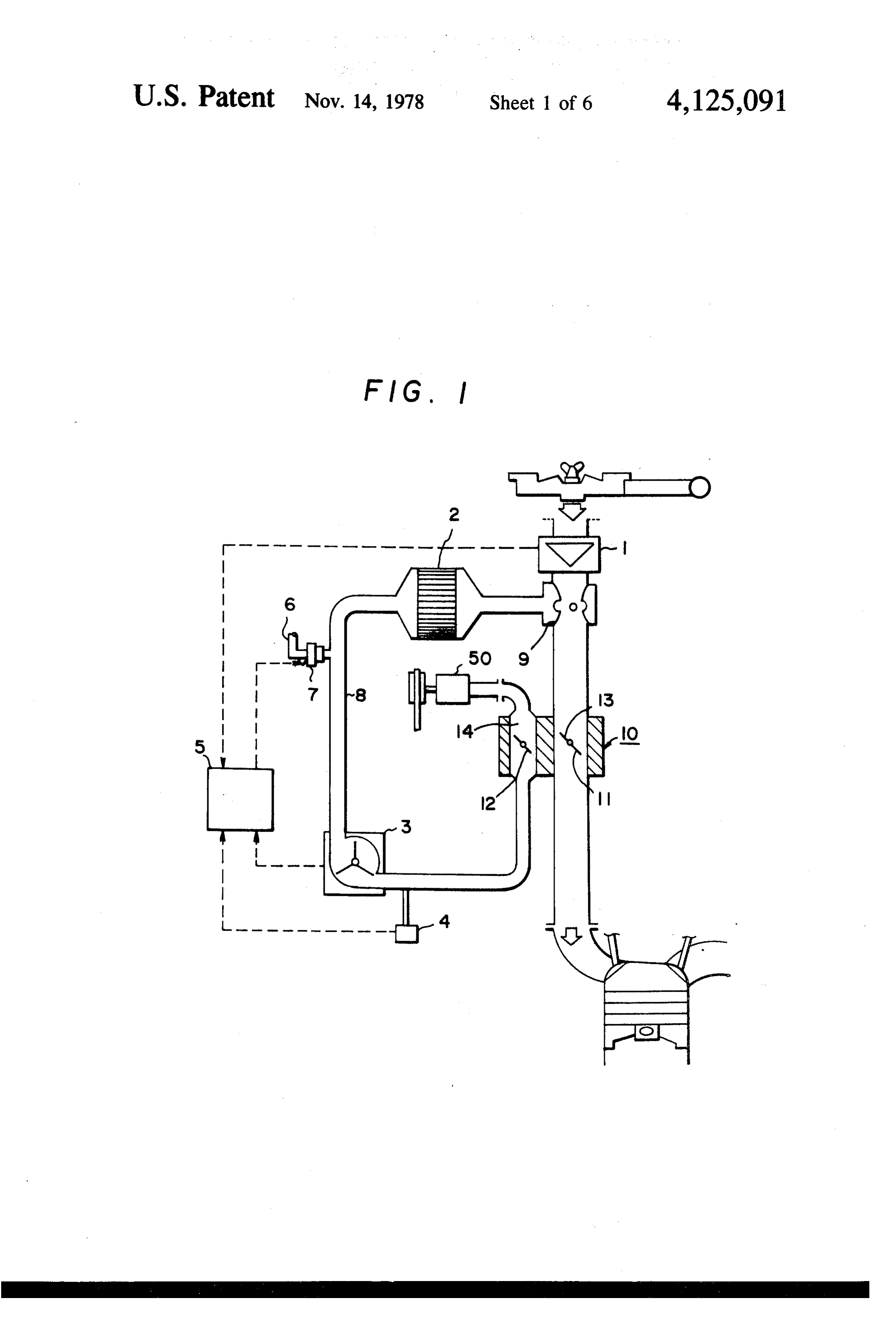
trol, while the internal combustion engine calls for an FIG. 1 illustrates a first embodiment of the present exact control. invention.
Page 9scan →
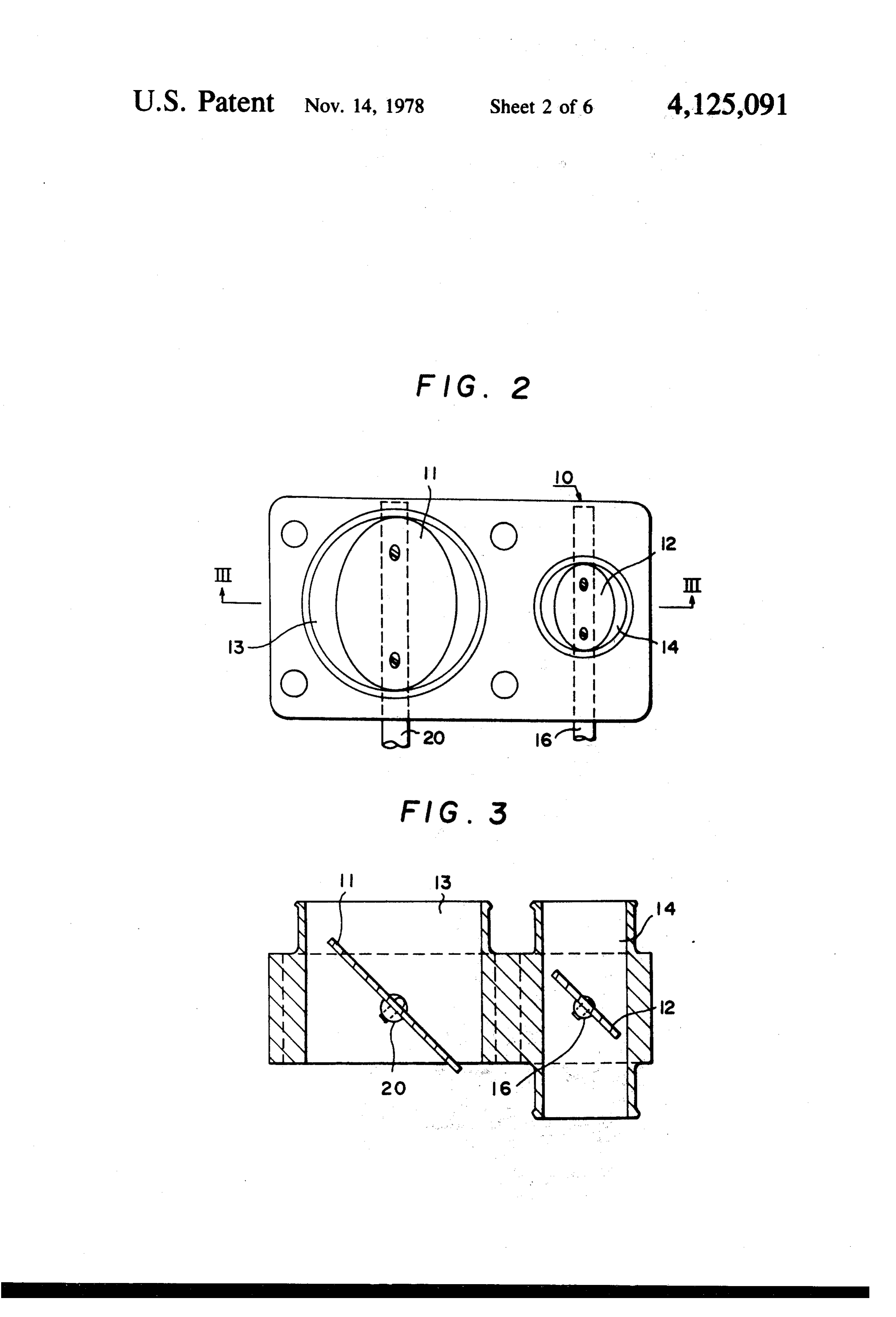
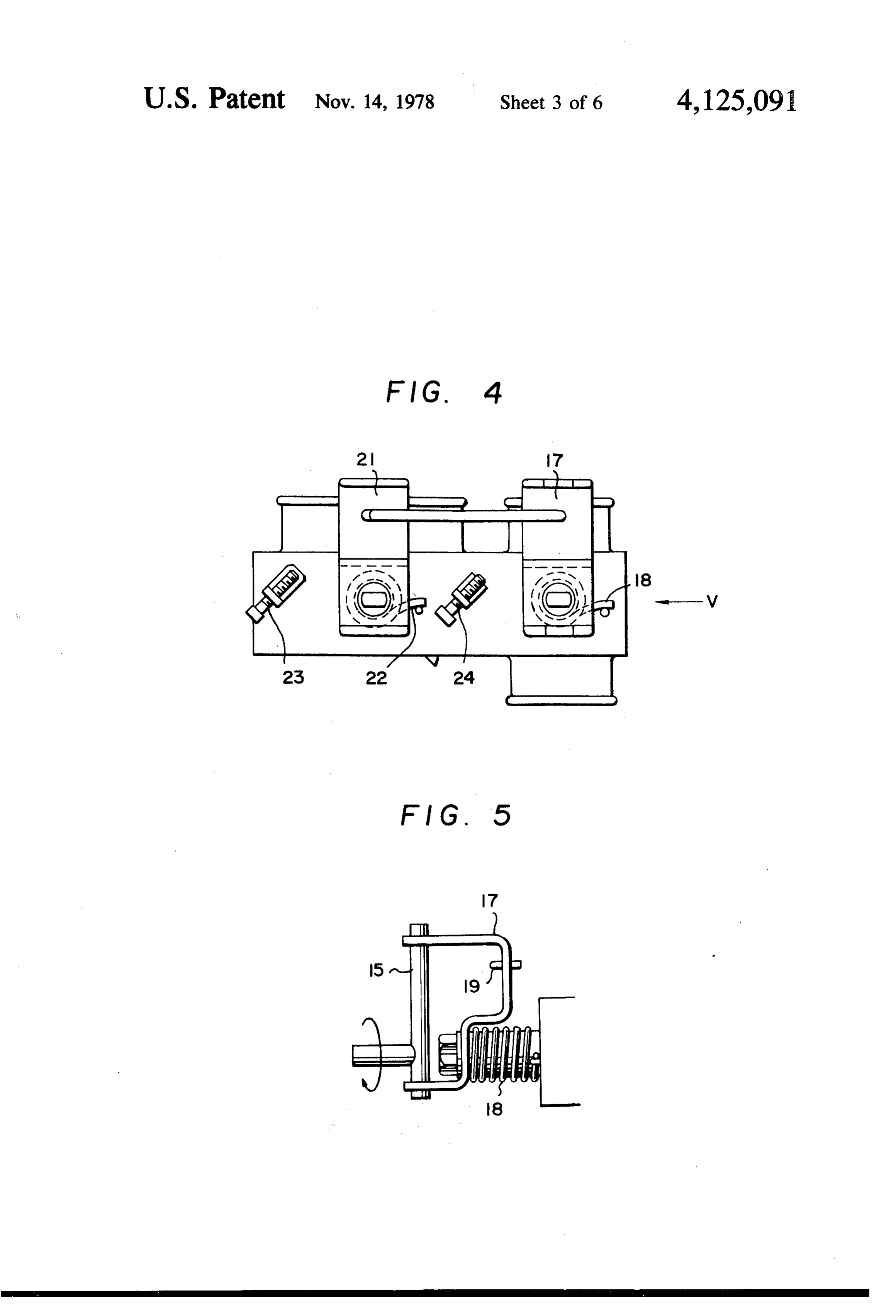
FIG. 2 is an enlarged plan view of a part of the con the total air volume, the insufficiency is corrected trol valve in FIG, . through an additional supply of fuel to the air not pass FIG. 3 is a section view along the line III-III in ing through the fuel-reforming device. When the fuel is F.G. 2. excessive, the excess is corrected by reducing the sup FIG. 4 is a front elevation view corresponding to ply of fuel into the air passing through the fuel-reform FIG. 2. ing device.
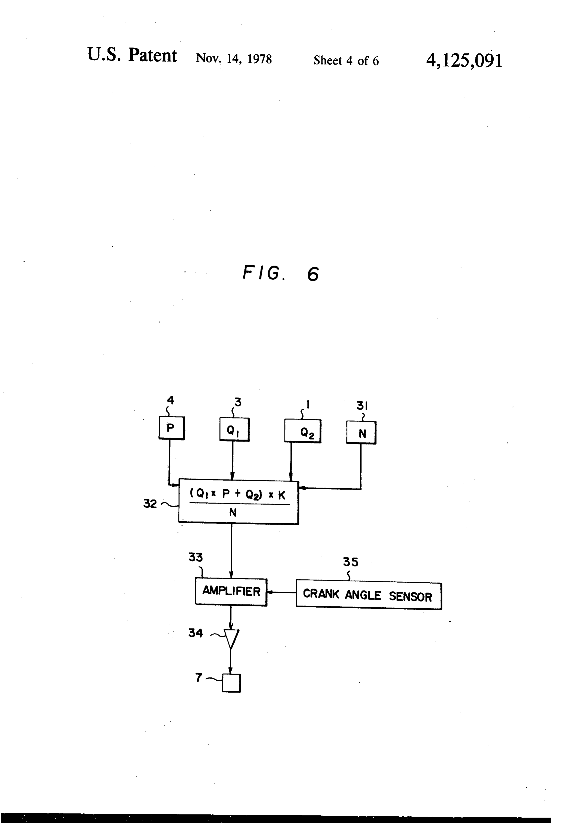
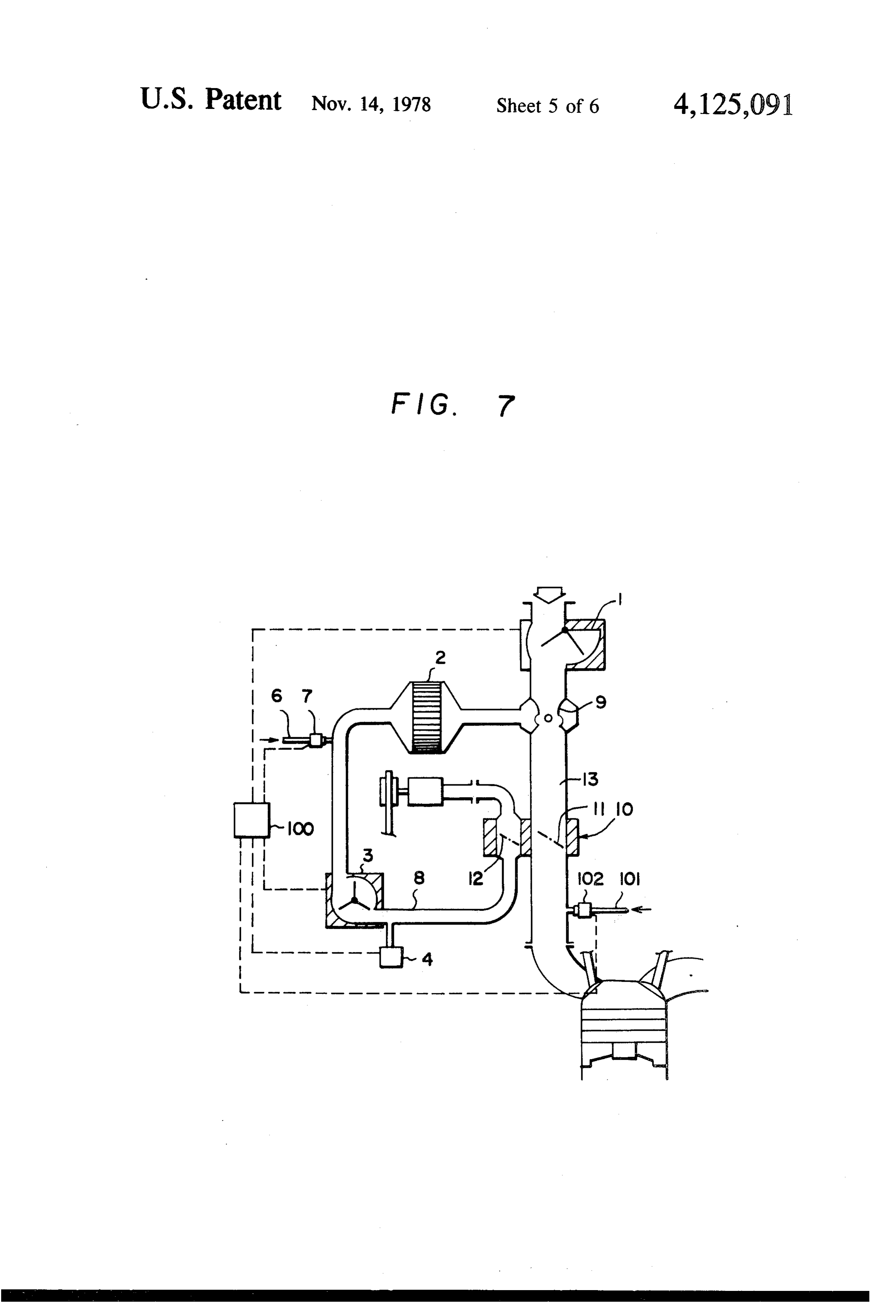
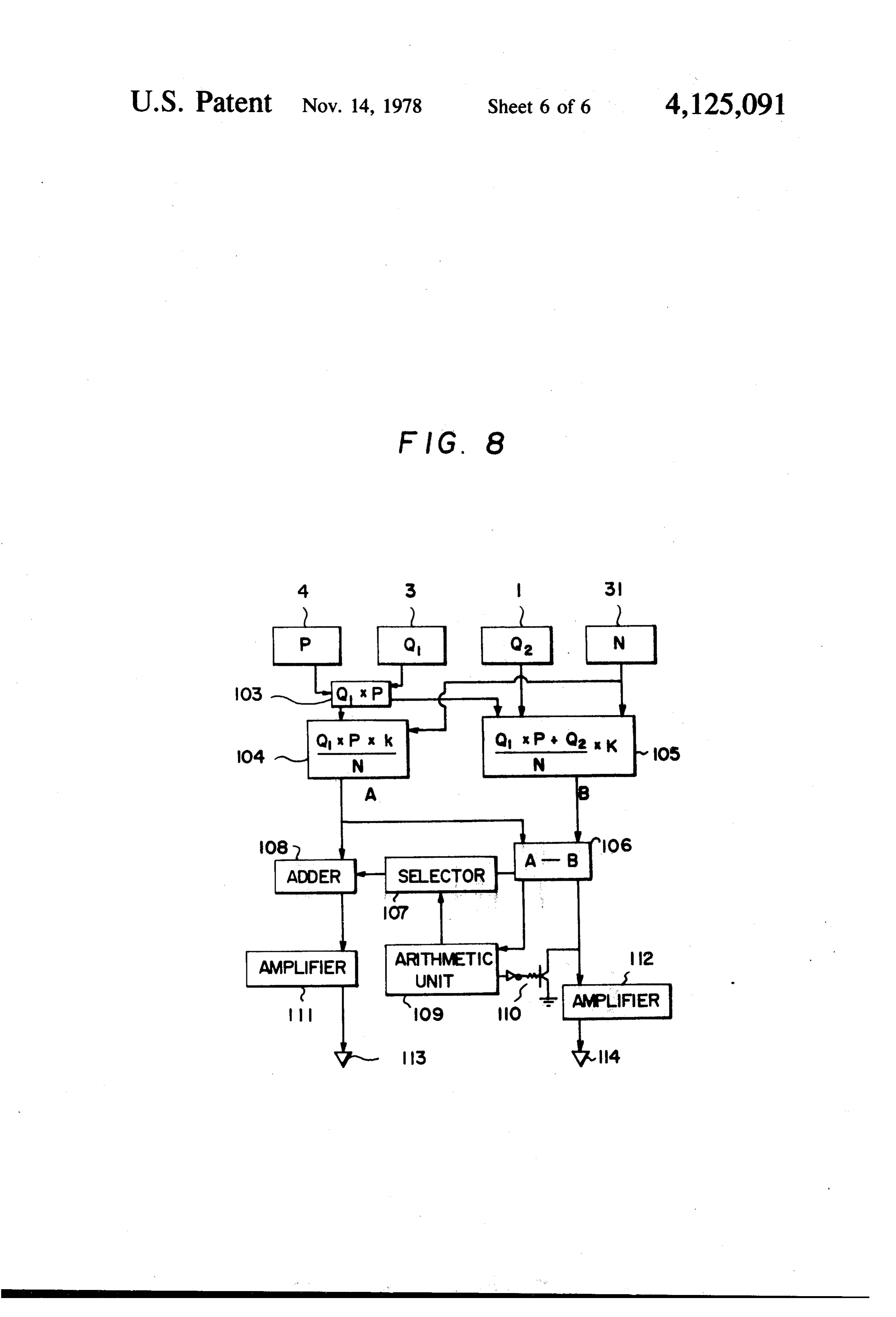
FIG. 5 is a side elevation view as viewed from the In these two embodiments, the supplied fuel and air arrow V in FIG. 4. react in partial oxidation in the fuel-reforming device, FIG. 6 is a block diagram of a controller in the first thereby yielding a reformed gas with a high content of embodiment of the present invention. 10 hydrogen. For effective generation of the reformed gas, FIG. 7 illustrates the second embodiment of the pres the ratio of air to fuel to be supplied to the fuel-reform ent invention. ing device should be set at 1.5-6 when the fuel is gaso FIG. 8 is a block diagram of a controller in the sec line.
ond embodiment of the present invention. For the purpose of preventing air pollution and ef. 15 fecting perfect combustion, the ratio of total air to total
DETAILED DESCRIPTION OF THE fuel should be controlled such that the combustion in PREFERRED EMBODIMENTS the engine can take place in the "lean' range. The method for control of a vehicle-mounted fuel The present invention will now be described in detail reforming device according to the present invention with reference to the drawings. In FIG. 1, an air volume comprises sucking into the internal combustion engine a 20 sensor 1 to measure the volume of the engine-sucked air throttle-valve controlled air without passing through is disposed in the engine suction path. The air is trans the fuel-reforming device; supplying to the fuel-reform mitted into the fuel-reforming device 2 through the air ing device by means of an air pump the air with its pump 50. In the air path to the fuel-reforming device are volume mechanically controlled by a valve interlocked installed an air volume sensor 3 to measure the volume with the throttle valve; detecting the volume of air not 25 of air to be sent into the fuel-reforming device 2 and a passing through the fuel-reforming device and the vol pressure sensor 4 to correct the flow rate in the air ume of air supplied to the fuel-reforming device to find volume sensor 3 by measuring the pressure of the air the total air volume sucked into the engine and deliver sent in. The signals from the air volume sensor 1, the air ing the volume of fuel matching the total air volume volume sensor 3 and the pressure sensor 4 are transmit into the air under electrical control; causing the air ted to the controller 5, where the total volume of air to supplied to the fuel reforming device and the fuel sup be delivered to the engine is calculated and the neces plied into the air to react together within the fuel sary volume of fuel to be supplied depending on the reforming device to yield a reformed gas; and supplying calculated air volume is claculated from a preset value. the reformed gas into the air not passing through the Upon a signal of the necessary fuel supply, the magnetic fuel-reforming device, upstream of the throttle valve. 35 valve 7 provided in the fuel pipe 6 acts to exactly mea Thus, according to the present invention, electrical sure the fuel, which is supplied in the air path 8 to the control is applied for measurement of air volume sucked fuel-reforming device 2. In the fuel-reforming device 2, in before a reformed gas is introduced into the engine, the air and the fuel mixed therewith react together and, for exact measurement of air volume sent to the fuel in the presence of a catalyst, yield a hydrogen-contain reforming device, for pressure detection of air sent to 40 ing reformed gas. In the mixer 9, the reformed fuel the fuel-reforming device and subsequent correction of blends with the engine-sucked air and the air/fuel ratio the air volume sent to the fuel-reforming device, for of the mixed gas is set so that harmful emissions can be calculation of the total air volume to be sucked upon a minimized. If the mixer 9 is a venturi type, a suction signal of the air volume measured into the engine con force proportional to the engine-sucked air volume will taining a reformed fuel, for calculation of the necessary 45 be indicated. Accordingly, the output of the air pump fuel supply to the fuel-reforming device depending on can be reduced.
the total air volume thus calculated, and for control of The sucked volume of the mixed gas, which goes into the fuel supply thus calculated to the fuel-reforming the engine and burns there, is controlled by the throttie device. Meanwhile, mechanical control is applied for valve 11 in the control valve 10, which is interlocked simultaneous coordinated control of the engine-sucked 50 with the acceleration pedal to be handled by the opera air volume and the fuel-reforming device-delivered air tor. The air path to the fuel-reforming device 2 is volume by means of two control valves coupled by, for equipped with a butterfly valve 12 to control the vol example, a linkage. ume of air sent to the fuel-reforming device 2. The The following two embodiments of the present in throttle valve 11 and the butterfly valve 12 are inter vention will now be described. 55 locked by a linkage. Thus, the flow rates in the path 13 In the first embodiment the fuel matching the total air provided with the throttle valve 11 and in the path 14 volume sucked into the engine is supplied, upstream of provided with the butterfly valve 12 are correlated. the fuel-reforming device, into the air passing through This correlation is so set as not to exceed a specific the fuel-reforming device. operational range required of the engine. In the second embodiment, the fuel is supplied re The constitution and function of the control valve spectively into the air supplied to the fuel-reforming assembly 10 will now be described in detail referring to device and into the air sucked into the engine without FIGS. 2 to 5. The major structural parts are the throttle passing through the fuel-reforming device. The fuel valve 11 and the butterfly valve 12. The sectional areas matching the total air volume sucked into the engine of the paths 13, 14 provided with these valves depend and the fuel matching the detected air volume passing 65 on the flow rate at maximum output and the average through the fuel-reforming device are supplied into the ratio between the air volume and the mixed gas volume air passing through the fuel-reforming device, upstream supplied to the fuel-reforming device 2. The assembly of the fuel-reforming device. When the fuel is short for 10 can be provided with various link mechanisms which
Page 10scan →
:5 6 give desirable valve opening characteristics. FIG. 3 The function of the amplifier 33 is to sense the crank illustrates an example in which the link mechanism is shaft position from the crank angle sensor 35, start the designed so that the valves 11 and 12 can be opened to action of the injector 34 upon this signal, and maintain approximately the same angle. the action of the injector for a period, matching the The force from the transmitting shaft 12 which is signal from the arithmetic unit 32.
operated by the operator and supported by another part In an actual test in which the engine-sucked air/fuel is transmitted to a stay 17 fixed with a nut to the stem 16 ratio was set at 19 and the sectional area ratio of the of the butterfly valve 12, and, overcoming the force of paths 13, 14 indicated in FIG. 2 or 3 was set at 4: 1, the the spring 18, it opens the butterfly valve 12. The link 19 variation of K was 19 -- 0.5 in the engine revolution is connected to a stay 21 fixed to the stem 20 of the other O range from 1,000 to 3,000 rpm and in the valve opening valve ill, and, acting together with the action of the stay range from 5 to full-open, while the variation of K was 17, it overcomes the force of the spring 22 and opens the 3.2 - 0.7. These values testify that the aim of the con throttle valve 11. The screws 23, 24 set the valve open trol method according to the present invention is com ing angle during idling and limit the movements of the pletely attained.
stays 21, 17 with which they come into contact during 15 As evident from the above description, when the idling. mcthod and equipment of the first embodiment of the The first method and the function of the equipment in present invention are employed, the air/fuel ratio Kin the first embodiment in FIG. will now be described. the internal combustion engine can be exactly con Designating the weight of air sent into the fuel trolled, the air/fuel ratio kin the fuel-reforming device reforming device 2 as gil, the volume of air sucked into 20 can also be mechanically controlled to the necessary the engine as g2 and the volume of fuel as f, the air/fuel range, and, accordingly, the is vehicle-mounted fuel ratio k in the fuel-reforming device 2 and the sucked reforming device can be controlled to a necessary and air/fuel ratio K in the engine can be generally ex sufficient extent. This can indirectly contribute to re pressed by:
25 ducing the size of the control equipment, saving installa tion space and decreasing manufacturing cost.
The second embodiment of the present invention will
K = (q1 + q2)/f (2) now be described with reference to the drawings. In FIG. 7 which illustrates the system of the second
If g1/q2 = t from (2) is obtained: 30 embodiment, like parts are denoted by like symbols and a detailed account is omitted.
gi/f-- g/if = K, (3) The major difference in the equipment between FIG. 7 and FIG. 1 lies in that a fuel supply pipe 101 and a
Substituting (1) into (3), there is obtained: magnetic valve 102 are also provided in the air path 13 ka + kg/t = K, (4) 35 2which does not pass through the fuel-reforming device and they are controlled by the controller 100.
And transforming (4), there is obtained: In FIG. 7, the volume of air supplied to the fuel reforming device 2 is detected by the air volume sensor t = k/(K-k) (5) 3 installed in the air path 8, while the pressure of the air measured by the pressure sensor 4 is used to correct the
When the fuel is gasoline, the maximum value of K air volume measured by the sensor 3. These measured will be 19 and the values of k range from 1.5 to 6. Thus, volumes are transmitted as electric signals to the con t = 0.09 - 0.46, that is, t has an extremely wide range troller 100, where the necessary fuel supply to the fuel of allowable values. reforming device 2 matching the measured air volume is According to the present invention, it is quite easy to 45 calculated and, therefore, the necessary volume of fuel arrange the mechanical control such that, in the control can be delivered through the action of the magnetic valve assembly, t = set value -- 0.03 or so. Thus, under valve 7 in the fuel supply pipe 6 provided in the air path the combination with electronic control which can 8 to supply the fuel, downstream of the sensor 3. Ac precisely regulate the value of Ko, it is possible to gener cordingly, the temperature in the fuel-reforming device ate a hydrogen-containing gas so that the harmful con 50 which usually becomes extremely hot can be held to a tents in the exhaust gas from the engine can be reduced. minimum required value.
The constitution as well as the function of the arith From the signals of the sensors 1,3 and 4, the control metic circuit of the controller 5 in the first embodiment ler 100 calculates the total air volume sucked into the will now be described. FIG. 6 illustrates the arithmetic engine and, through comparison with the preset volume circuit of the controller 5. The signal Q1 proportional to 55 of fuel needed for the total air volume, determines an the air volume from the sensor 31 of the air volume to excess or an insufficiency of the fuel. In the case of an the reforming device 2, the signal P matching the pres insufficiency, the magnetic valve 102 installed in the sure of air from the pressure sensor 4, the signal Q2 fuel supply pipe 101 which supplies the fuel without proportional to the air volume from the engine-sucked passing through the fuel-reforming device 2 acts to air volume sensor 1, the signal N proportional to the supply the fuel directly to the engine without passing rpm from the engine revolution sensor 31 and the factor through the fuel-reforming device 2. When the fuel K to determine the engine air/fuel ratio are converted supplied to the air path 8 through the valve 7 for the in the arithmetic unit 32 to a signal (Q1 X P + Q2)/NX preset total air/fuel ratio is excessive, the controller 100 K which activates the injector 34 through the amplifier activates the valve 7, thereby reducing the volume of 33. Action of the injector 34 causes the magnetic valve 65 fuel passing through the valve 7 so that the total air/fuel 7 to open, thereby supplying the fuel to the air path 8. ratio may meet the preset value: This preset value is The pressure sensor 4 may be omitted and, in that case, such that the engine can burn in the "lean' range, the signal P will invariably be 1. thereby enhancing the thermal efficiency of the engine 11 as well as decreasing the harmful content of the exhaust ratio in the fuel-reforming device 2 is apt to become gas. rather high. Therefore, it is desirable to set a low value. Referring to FIG. 8, the arithmetic circuit of the Being usually set at about 3, the air/fuel ratio in the controller 100 in the second embodiment will now be fuel-reforming device 2 is unlikely to be forced out of described. the allowable range.
The signal P proportional to the pressure of air sup The air/fuel ratio in the fuel-reforming device 2, the plied to the fuel-reforming device 2 which is transmit total air/total fuel ratio in the engine, the performance ted from the pressure sensor 4 and the signal Q1 propor of the engine, and the effective contents in the exhaust tional to the air volume transmitted from the sensor 3 of gas are related to one another as follows. Assuming that the air volume supplied to the reforming device are 10 the volume of fuel passing through the valve 7 is fi; the converted in the arithmetic unit 103 to a signal Q X P. value of a1 = g1/f, where q1 is the volume of air in the This signal, the signal N from the engine revolution fuel-reforming device and is constant; and the ratio of sensor 31 and the factor K to determine the air/fuel the total air volume q1 + q2 to the total fuel volume f ratio in the reforming device 2 are converted in the -- f2, where f is the volume of fuel passing through the arithmetic unit 104 to a signal (Q1 X PX K)/N. On the 15 valve 102, that is, a2 = (q1 + q2)/(f - f2), is constant. other hand, the signal produced in the arithmetic unit Then, the following equations hold: 103, the signal Q2 proportional to the air volume which is transmitted from the engine sucked into the air vol ume sensor 1, the signal N and the factor K to determine the air/fuel ratio in the engine are converted in the 20 arithmetic unit 105 to a signal (Q1 X P -- Q2)/N X K.
Then, the signal (A) from the arithmetic unit 104 and the signal (B) from the arithmetic unit 105 are converted If a 1/a2 = d and f/fl = S, then from (1), (2) and (3) in the subtractor 106 to a signal A - B. If the signal A - is obtained:
B is positive, the arithmetic unit 109 acts on the selector 25 107, thereby rendering a zero signal to the adder 108. s = d/c - d - 1 (4) Then, the signal A(A + 0 = A) is sent to the amplifier 111 to activate the injector 113, while the transistor 110 Thus, s increases with a decrease in c namely f be does not act and the amplifier 112 is activated depend comes more than f. In consequence, the volume of fuel ing on the signal A - B. 30 delivered to the fuel-reforming device 2 decreases, If the signal A - B is negative, the arithmetic unit 109 while the volume of fuel which goes directly to the air activates the transistor 110, thereby grounding the sig path 13 increases. Thus, a fuel with high calorific value nal to the amplifier 112 and stopping the action of the per unit volume is burned in the engine. Namely, when injector 114. Meanwhile, the signal A - B is sent from the operator opens the valve 11 to increase the output, the selector 107 to the adder 108. Then, as a result of a 35 a fuel with high calorific value per unit volume is deliv negative signal being added, the signal to the amplifier ered to the engine, whereby the engine can maintain 111 is correspondingly reduced, thereby restricting the high performance. Conversely, in operation in urban action of the injector 113. areas when the valve 11 is half-open, the fuel and air The pressure sensor 7 may be omitted and, in that passing through the fuel-reforming device 2 increase, case, the signal P will invariably be 1. The injector 113 40 resulting in an increase in the reformed gas and in a causes the action of the valve 7, while the injector 114 decrease in the harmful content of exhaust gas. causes that of the valve 102. The value off/f depends on the characteristic of The factor K to determine the air/fuel ratio in the interlocking the valves 11 and 12. This characteristic is reforming device 2 is a constant value, but the factor K considered in designing and manufacturing the mecha to determine the air/fuel ratio in the engine which has a 45 nism interlocking the valves 11 and 12, for example, a great bearing on the exhaust composition and the ther linkage, and the valves 11, 12 themselves. Basically, mal efficiency of the engine may be set as a function of however, such a desirable characteristic is assured and the engine revolution and the engine load. therefore great caution is not required in high load If the injector 114 is designed and adjusted such that designing.
it can work in virtually the whole range of operation, 50 Thus, the following effects can be expected from the that is, in practically the whole range of A - B values, method and equipment of the second embodiment of the the engine can always run in satisfactory condition present invention.
regardless of the reforming device which is liable to be According to this method which combines electrical slow in response to sudden acceleration or deceleration. control with mechanical control, the equipment can be The function of the equipment of the second embodi 55 made compact and inexpensive with the necessary per ment of the present invention will now be described. formance, particularly the engine-sucked total air/fuel The controllable range of air/fuel ratios in the fuel ratio maintained with high precision. reforming device 2 depends mainly on the catalyst, but, According to this method, under high frequency of if the ratio is appropriately taken in the range of 1.5-6, using the fuel-reforming device, the volume of fuel a reformed gas with a superior burning characteristic 60 passing through the fuel-reforming device can be in will be yielded. According to the method of the inven creased; the gas can be burned with extremely little tion in which the air/fuel ratio in the fuel-reforming content of harmful elements; under high load, the vol device 2 is electrically controlled, the air/fuel ratio can ume of fuel not passing through the fuel-reforming be stable in practically the whole range. device can be increased to increase the output; and, In an internal combustion with a fuel-reforming de 65 accordingly, under all the working conditions of the vice 2, when it becomes necessary to maintain a fuel engine, the fuel can be appropriately controlled. supply to the fuel-reforming device 2 with a modified According to this method in which the fuel supply to air/fuel ratio in the fuel-reforming device 2, the air/fuel the fuel-reforming device and the total fuel supply to 12 the engine are cleverly controlled meeting respective 5. The method of claim 1 wherein the detected vol air supplies, the heat loss unavoidable in the fuel ume of air supplied to the fuel-reforming device is cor reforming device can be redeemed through an increased rected by separately detecting the pressure of air. efficiency of the engine, thereby minimizing the fuel 6. The method of claim 1 wherein gasoline is em consumption. ployed as the fuel and the air/fuel ratio in the fuel According to this method in which the fuel is sup reforming device is set at 1.5-6.
plied under electrical control to the fuel-reforming de 7. The method of claim 1 wherein the total air/total vice, the temperature in the fuel-reforming device fuel ratio in the engine is set so that the combustion in which becomes extremely high can be held to a neces the engine can take place in the lean range. sary minimum, thereby increasing the durability of the 10 8. Equipment for control of an internal combustion fuel-reforming device. engine with a fuel-reforming device comprising: And, according to this method which provides a a first path connected to the engine and having a system to supply air and fuel to the engine without throttle valve;
passing through the fuel-reforming device, the engine 15 a second path branching off the first path at a position can run with safety even when the fuel-reforming de upstream of the throttle valve; vice fails for some cause and loses its function. a fuel-reforming device disposed in the second path; Obviously, numerous modifications and variations of an air pump to send the air to the fuel-reforming the present invention are possible in light of the above device disposed in the second path; teachings. It is therefore to be understood that within 20 a valve mechanically interlocked with the throttle the scope of the appended claims the invention may be valve disposed in the second path; practiced otherwise than as specifically described a first air volume sensor disposed in the first path; herein. a second air volume sensor disposed in the second path;
What is claimed as new and desired to be secured by a fuel supply pipe disposed in one of said first and letters patent of the United States is: 25 second paths; and 1. A method for control of an internal combustion an electrical controller for calculating the total air engine with a fuel-reforming device comprising: volume sucked into the engine from the signals sucking into the engine air under control by a throttle from the first air volume sensor and the second air valve without passing through the fuel-reforming volume sensor and supplying the volume of fuel device; 30 matching the calculated total air volume through supplying air under mechanical control of its volume the fuel supply pipe.
by a valve interlocked with the throttle valve, to 9. Equipment in accordance with claim 8 wherein the the fuel-reforming device by means of an air pump; fuel supply pipe branches off the second path only at a detecting the volume of air not passing through the position upstream of the fuel-reforming device and the fuel-reforming device and the volume of air sup 35 volume of fuel matching the total air volume sucked plied to the fuel-reforming device to find the total into the engine is supplied through the fuel supply pipe air volume sucked into the engine and supplying into the air passing through the second path. the volume of fuel matching the total air volume 10. Equipment in accordance with claim 8 wherein under electrical control into the air; the fuel supply pipe is disposed both at a position up reacting the air supplied to the fuel-reforming device stream of the fuel-reforming device in the second path with the fuel supplied into the air in the fuel and in the first path; the controller supplies the volume reforming device to yield a reformed gas; and of fuel matching the air volume passing through the supplying the reformed gas into the air not passing second path, through the fuel supply pipe disposed in through the fuel-reforming device, upstream of the 45 the second path; when the fuel supply to match the total throttle valve. air volume sucked into the engine is insufficient, the 2. The method of claim 1 wherein the volume of fuel insufficiency is corrected by increasing the fuel supply matching the total air volume sucked into the engine is through the fuel supply pipe provided in the first path; supplied into the air passing through the fuel-reforming and, when the fuel supply is excessive, the excess is corrected by decreasing the fuel supply through the fuel device, upstream of the fuel-reforming device. 50 supply pipe disposed in the second path. 3. The method of claim 1 wherein the fuel is supplied 11. Equipment in accordance with claim 8 wherein respectively into the air supplied to the fuel-reforming the fuel-reforming device controls a reformed gas con device and into the air sucked into the engine without passing through the fuel-reforming device; the volume taining a large quantity of hydrogen through partial oxidation reaction of gasoline and air received.
of fuel matching the detected air volume passing 55 12. Equipment in accordance with claim 8 wherein through the fuel-reforming device is supplied into the the controller adjusts the air/fuel ratio in the fuel air passing through the fuel-reforming device, upstream reforming device to 1.5-6.
of the fuel-reforming device; when the supply of fuel matching the total air volume sucked into the engine is the13.controller
Equipment in accordance with claim 8 wherein insufficient, the insufficiency is corrected by increasing engine so thatadjusts the total air/total fuel ratio in the the combustion in the engine can take the fuel supply to the air not passing through the fuel place in the lean range.
reforming device; and when the supply of fuel is exces 14. Equipment in accordance with claim 8 wherein a sive, the excess is corrected by decreasing the fuel sup pressure sensor in addition to the second air volume ply to the air passing through the fuel-reforming device. sensor is disposed in the second path and the signal from 4. The method of claim 1 wherein a reformed gas 65 the pressure sensor is transmitted to the controller to containing a large quantity of hydrogen is controlled increase the detecting accuracy of the air volume. through a partial oxidation reaction of gasoline and air 15. Equipment in accordance with claim 8 wherein in the fuel-reforming device. the throttle valve and the valve in the second path are 13 mechanically interlocked by a link mechanism and the pipe and operated to open or close upon a signal from valves are openable to the same angle. the controller. o 16. Equi d ith claim 8 wherei 17. Equipment in accordance with claim 8 wherein a . Equipment in accordance with claim 8 wherein mixer is disposed at a point of the second path branch the fuel supply through the fuel supply pipe is con- 5 ing off the first path.
trolled by a magnetic valve disposed in the fuel supply is
Provenance
- Collection
- Patents citing this work
- Pages
- 13
- Method
- pdftotext (the PDF's own text layer) + pdftoppm 300dpi page scans
- Patent office record
- patents.google.com →
- Source
- Google Patents citing-documents table
- Assignee
- Toyota Jidosha Kogyo Kabushiki Kaisha
- Published
- 1978-11-14
- Transcribed from
- patentimages.storage.googleapis.com →