

patent · US4119061A
Method and equipment for control of internal combustion engine including a fuel-reforming device
10 October 1978
Text
Page 1bibliographic recordscan →
Hoshi et al.
54 METHOD AND EQUIPMENT FOR
CONTROL OF INTERNAL COMBUSTION
ENGINE INCLUDING A FUEL-REFORMING
DEVICE
Inventors: Hirohiko Hoshi; Toshio Funayama; Kazuhiko Ishiguro, all of Toyota;
Hidetomo Umehara, Susono, all of
Japan Assignee: Toyota Jidosha Kogyo Kabushiki
Kaisha, Japan
(30) Foreign Application Priority Data
Nov. 18, 1976 JP Japan ................................ 51-138648 Int. Cl. .............................................. F02B 43/08 52 U.S.C. ........................................ 123/3; 123/127;
1,966,345 7/1934 Harrel .................................. 123/121 4,002,151 l/1977 Toyoda .................................... 123/3 4,026,248 5/1977 Lee ........................................... 123/3
4,059,076 11/1977 Kosaka ..................................... 123/3
FOREIGN PATENT DOCUMENTS
Primary Examiner-Ronald H. Lazarus
Attorney, Agent, or Firm-Oblon, Fisher, Spivak, McClelland & Maier
Method and equipment for control of an internal com bustion engine including a fuel-reforming device in cludes appropriate control of the ratio of total air to total fuel supplied to the internal combustion engine through mechanical regulation of the volume of air to pass through the fuel-reforming device in accordance with the volume of air to be sucked into the engine without passing through the fuel-reforming device, suction being done utilizing the negative pressure downstream of the throttle valve; through electrical regulation of the volume of fuel to be supplied to the air passing through the fuel-reforming device in accor dance with the volume of the air; and through electrical control of a separate fuel-supply provided in the air path which does not run through the fuel-reforming device and of a fuel-supply which runs through the fuel reforming device.
11 Claims, 4 Drawing Figures
Drawings
Page 2drawing sheetscan →
Page 3drawing sheetscan →
Page 4drawing sheetscan →
Page 5drawing sheetscan →
Page 6scan →
which becomes extremely hot with an increased supply
METHOD AND EQUIPMENT FOR CONTROL OF of materials is prevented from rising to an excessively INTERNAL COMBUSTION ENGINE INCLUDING high value by holding the volume of the supply to a A FUEL REFORMING DEVICE necessary minimum, thereby increasing the durability of BACKGROUND OF THE INVENTION the fuel-reforming device.
1. Field of the Invention
Still another object of the present invention is to provide a method and equipment for control of an inter
The present invention relates to a method and equip nal combustion engine with a fuel-reforming device ment for control of fuel and air to be supplied to an wherein the engine can run even when the air supply to internal combustion engine comprising a fuel-reforming 10 the fuel-reforming device drops or ceases or even when device. the fuel-reforming device loses its function. 2. Description of the Prior Art Still another object of the present invention is to It is known that when an internal combustion engine provide a method and equipment for control of an inter is supplied with a hydrogen-containing gas from a fuel nal combustion engine with a fuel-reforming device reforming device, a very "lean' combustion is made 15 wherein the air supply possible, thereby reducing the harmful exhaust gas. For done mainly by utilizingto the the fuel-reforming device is negative pressure in the the purpose of reforming the fuel, the so-called partial suction pipe, thereby dispensing with the air pump oxidation method, in which the air and hydrocarbons which is usually required.
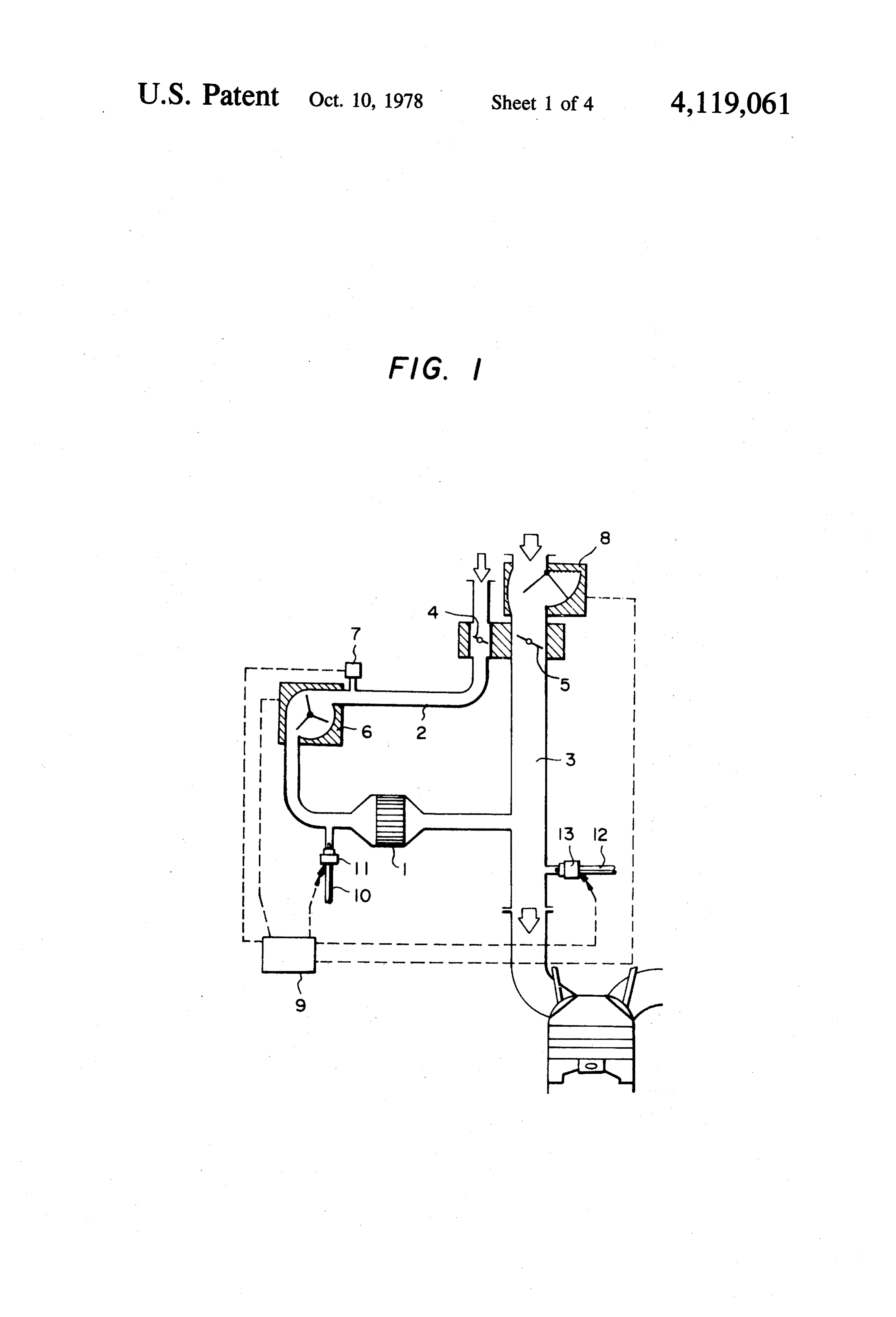
are made to react on the catalyst bed under the condi tion of very little air, is often adopted. According to this 20 BRIEF DESCRIPTION OF THE DRAWINGS method, the ratio of air to fuel to be supplied to the fuel-reforming device and the air excess rate in the theVarious present objects, features and attendant advantages of invention will be more fully appreciated as engine have their optimum values. For the purpose of the same becomes optimizing these two values, various methods of electri detailed descriptionbetter of understood from the following the present invention when con cal or mechanical control have been employed. 25 sidered in connection with the accompanying drawings
Although the conventional method of electrical con in which:
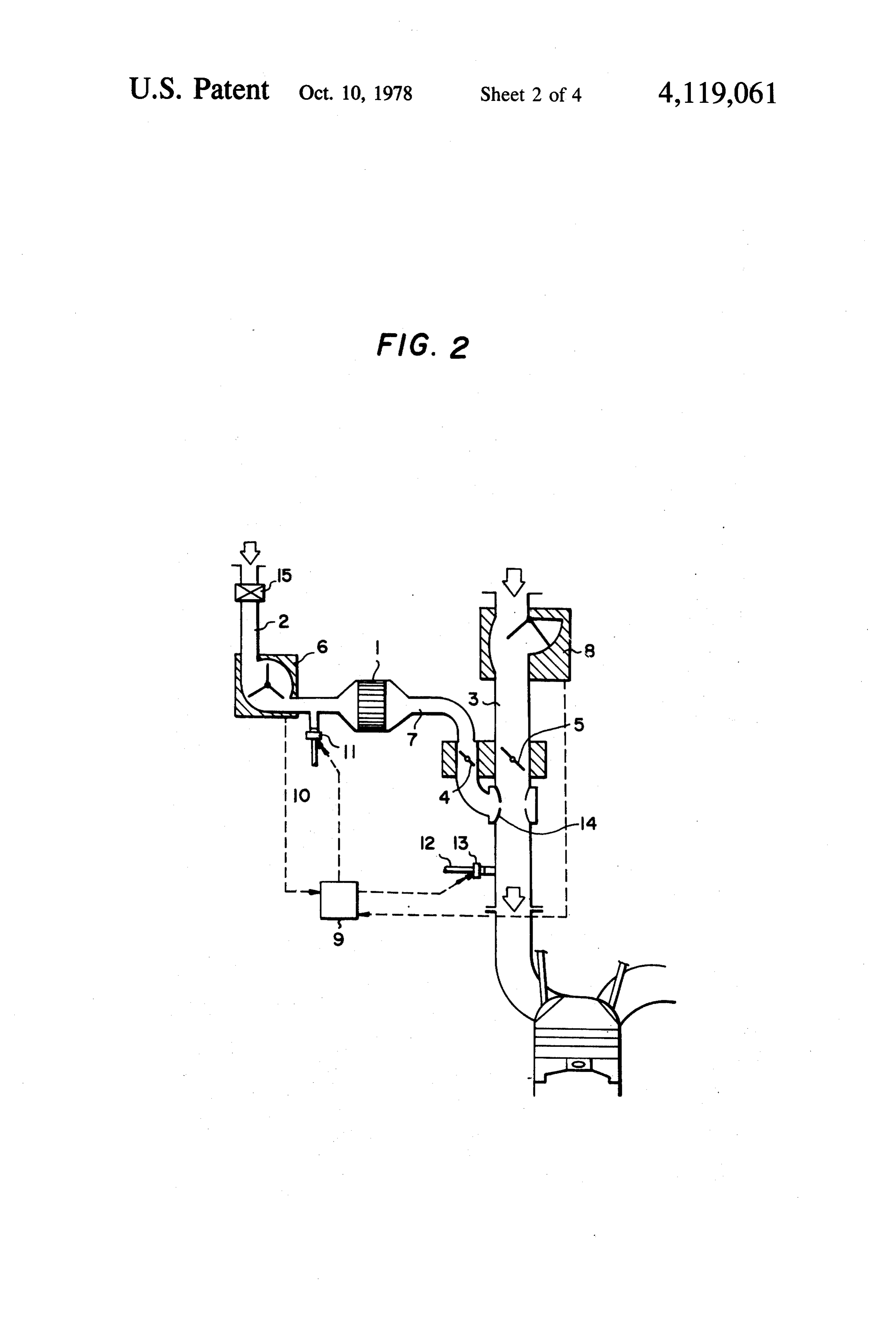
trol is capable of relatively accurate control, it leaves much to be improved because it requires a complicated, FIG. 1 illustrates a system according to the first em bulky apparatus including a feedback circuit. When the bodiment of the present invention. ratio of air to hydrocarbons to be delivered to the fuel 30 FIG. 2 illustrates a system according to the second reforming device is mechanically controlled by means embodiment of the present invention.
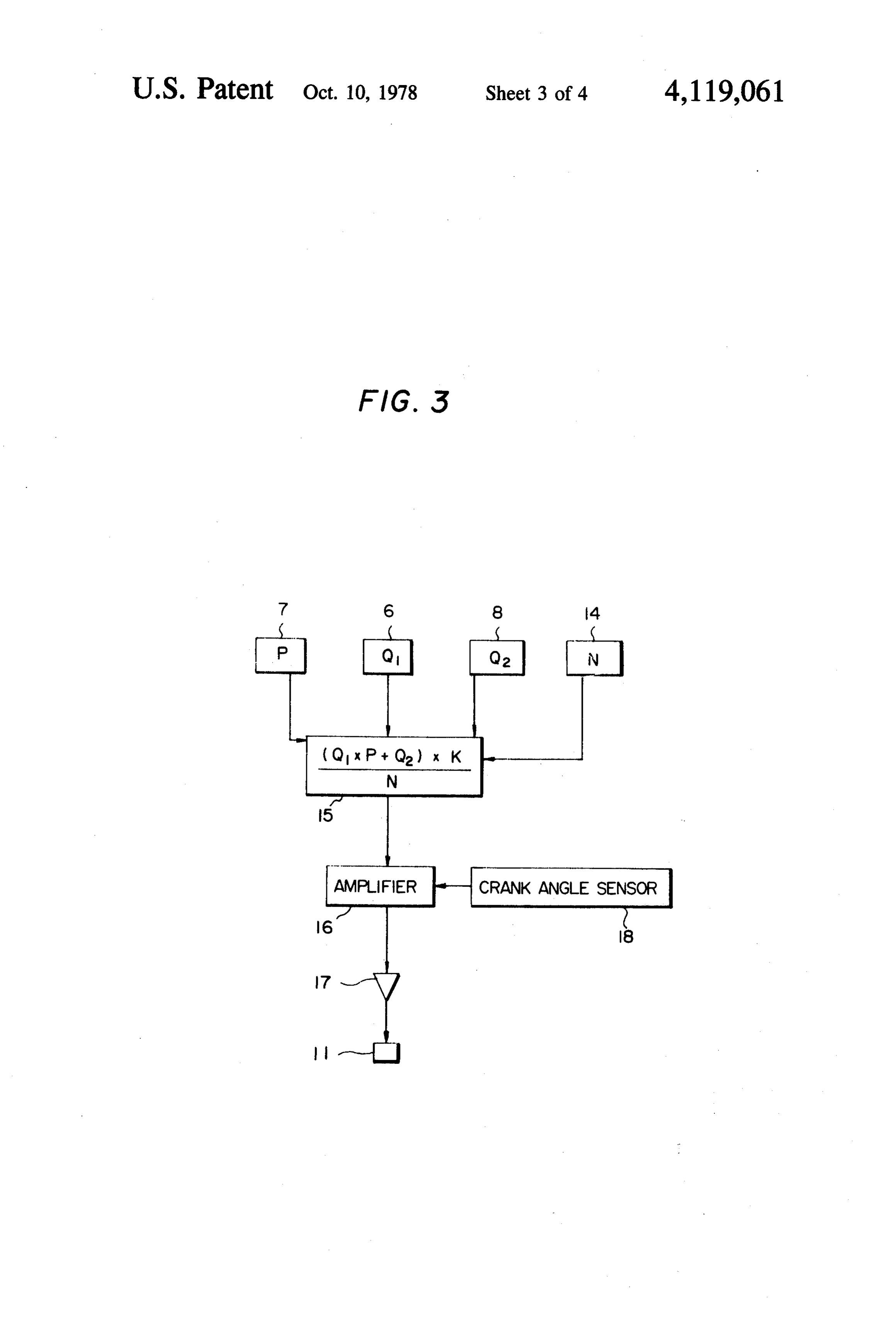
of the carburetor, the apparatus can be made less bulky theFIG. 3 is a block diagram illustrating a controller in first embodiment.
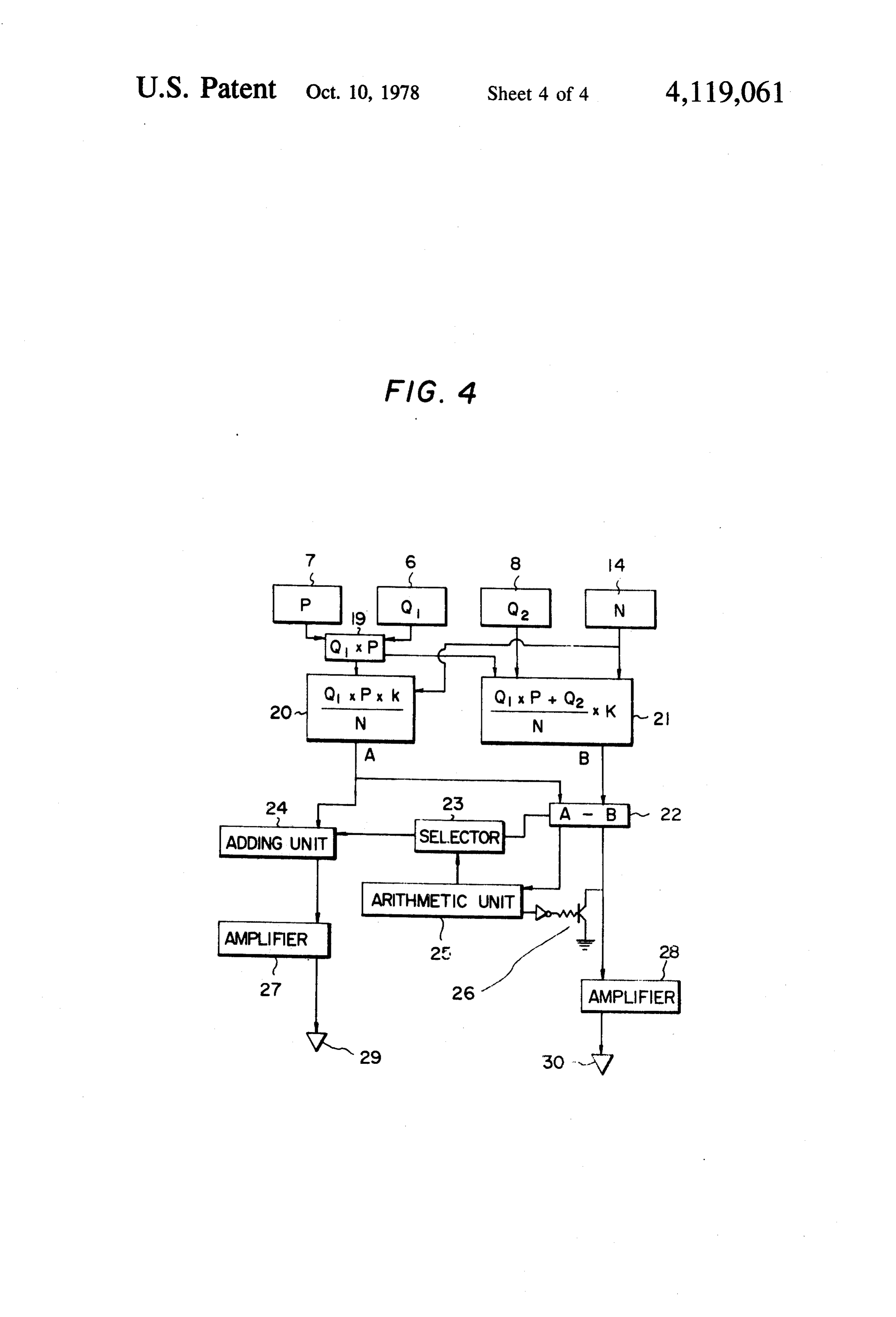
than in the electrical method. Under the condition of extremely little air, for example, the weight ratio of air FIG. 4 is a block diagram illustrating a controller in to hydrocarbons being less than 3, only unreliable and 35 the second embodiment.
rough control can be made. This adverse effect emerges DETALED DESCRIPTION OF THE in the air excess rate of the engine which has a direct PREFERRED EMBODIMENTS bearing on the harmful contents of the exhaust gas or the fuel consumption rate. The method according to the present invention com 40 prises sucking the air into the engine without passing
SUMMARY OF THE INVENTION through the fuel-reforming device; sucking the air, uti A main object of the present invention is to provide a lizing the negative pressure downstream of a throttle method and equipment for control of an internal com valve, through the fuel-reforming device, into the air bustion engine with a fuel-reforming device in which which has not passed through the fuel-reforming de the electrical control unit is made compact and simple 45 vice, the throttle valve serving to control the flow rate through adoption of mechanical control to be coupled of the air; regulating the flow rate of the air passing with electrical control. through the fuel-reforming device in accordance with Another object of the present invention is to provide the flow rate of the air not passing through the fuel a method and equipment for control of an internal com reforming device by interlocking the throttle valve bustion engine with a fuel-reforming device wherein the 50 with a valve to control the flow rate of the air not pass fuel-reforming device is intended mainly for use in a ing through the fuel-reforming device; detecting the partial load range where service is required often such flow rate of the air passing through the fuel-reforming as when running through urban areas. In this load device, electrically calculating the volume of fuel to be range, the internal combustion engine yields very little supplied to the fuel-reforming device in accordance harmful exhaust gas. Therefore, the performance of the 55 with the detected flow rate of the air, and supplying the engine in the high load range is not sacrificed. calculated volume of fuel to the air passing through the Still another object of the present invention is to fuel-reforming device; reacting the fuel with the air provide a method and equipment for control of an inter passing through the fuel-reforming device in the fuel nal combustion engine with a fuel-reforming device reforming device, thereby yielding a reformed gas; and wherein the combustion of the mixed gas takes place calculating the flow rate of the air not passing through usually in the "lean' range and the heat loss in the fuel the fuel-reforming device, finding the total volume of reforming device is redeemed through an increase in the air sucked into the engine from the sum of the calcu thermal efficiency of the engine, thereby holding down lated air volume and the detected volume of the air the total fuel consumption. passing through the fuel-reforming device, electrically Still another object of the present invention is to 65 calculating the necessary volume of fuel for the total air provide a method and equipment for control of an inter volume, whereby a lack in the fuel is corrected by sup nal combustion engine with a fuel-reforming device plying the necessary amount of fuel to the air not pass wherein the temperature in the fuel-reforming device ing through the fuel-reforming device and an excess in 7 the fuel is corrected by reducing the fuel to be supplied the controller 9, where the total air volume sucked into to the air passing through the fuel-reforming device. the engine is found from the signal of the sensor 8 and Mechanical regulation of the volume of air passing the signals of the sensors 6 and 7. Then, the lack or through the fuel-reforming device may be done up excess of fuel is determined in comparison with the stream of the fuel-reforming device or downstream of 5 predetermined necessary volume for the total air vol it. ume. In the case of a deficiency, a magnetic valve 13 For the purpose of increasing the accuracy of mea provided in the fuel supply pipe 12 to supply the fuel suring the flow rate of the air passing through the fuel without passing through the fuel-reforming device 1 is reforming device, in addition to a flow-meter to mea operated, thereby directly supplying the fuel to the sure the flow of the air passing through the fuel-reform 10 engine without passing through the fuel-reforming de ing device, a pressure-detecting means may be provided vice 1. In the case of an excess, fuel is supplied to air so that a signal thereof may be sent to the controller and path 2 passing through the magnetic valve 11. In con correction may be made with this signal. sideration of the ratio of the total air to the total fuel, the The ratio of total air to total fuel to be supplied to the controller 9 works the magnetic valve 11, thereby re engine is thus controlled such that the combustion in the 15 ducing the volume of fuel passing through the magnetic engine may take place. in the "lean' range, thereby valve 11 so that the ratio of total air to total fuel may reducing the harmful exhaust gas and improving the meet the preset value. The preset value is decided so thermal efficiency of the engine. that the combustion in the engine may take place in the An example of the method according to the present "lean' range, thereby reducing the harmful exhaust gas invention is shown in FIG. 1 which illustrates a system 20 and improving the thermal efficiency of the engine. as the first embodiment of the present invention. In this FIG. 2 illustrates the second embodiment of the pres system, the internal combustion engine is supplied with ent invention, where like parts are denoted by like sym the air sucked through the air path (suction pipe) 3 bols in the first embodiment and a detailed account is without passing through the fuel-reforming device 1; omitted. The air volume supplied to the fuel-reforming the fuel which is supplied to the air from a supply sys 25 device 1 is detected by the air volume sensor 6 provided tem if necessary; the air sucked into the air which has in the air path 2. The controller9 activates the magnetic not passed through the fuel-reforming device 1 down valve 11 in the fuel pipe 10, whereupon the volume of stream of a throttle valve 5 which controls the air; and fuel matching the volume of air passing through the air the fuel which is supplied to the air passing through the path 2 is supplied downstream of the air volume sensor fuel-reforming device 1, upstream of the fuel-reforming 30 6 in the air path 2 and upstream of the fuel-reforming device 1. device 1. Hydrogen-containing reformed gas produced This system in which the air supply to the fuel through reaction in the fuel-reforming device 1 is ad reforming device 1 takes place through suction under justed in its flow rate by the valve 4 mechanically inter the negative pressure developed downstream of the locked with the valve 5 provided in the air suction pipe valve 5 of the suction pipe 3 does not require an air 35 3 midway in the path 7 of the reformed gas and is mixed pump which is conventionally provided in the air sup in the mixer 14 provided in the air path 3 downstream of ply path 2 to the fuel-reforming device 1. Of course, the valve 5 (in the example of FIG. 1, a mixer is not such an air pump may be provided if it desirably en shown but, of course, one may be provided) and is then larges the applicabilities of the fuel-reforming device 1. delivered to the engine.
There is a valve 4 in the air supply path 2 to the 40 Sensing the total air volume supplied to the engine fuel-reforming device 1. The valve 4 and the valve 5 are upon the signal from the air volume sensor 8 in the pipe mechanically interlocked by, for example, a linkage, 3 upstream of the valve 5 and the signal from the air whereby the control of the air passing through the volume sensor 6 in the air path 2, the controller 9 deter fuel-reforming device 1 is mechanically associated with mines a lack or excess of fuel through comparison with the control of the air not passing through it. Since this 45 the present ratio of total air to total fuel. In the case of interlocking is mechanical, the control device can be a deficiency, the necessary fuel is supplied into the air or compact and simple as compared with the conventional the mixed gas containing the hydrogen-containing re one using an electrical method of control. formed gas in the pipe 3, downstream of the valve 5, by The volume of the air supplied to the fuel-reforming operating the magnetic valve 13 provided in the fuel device 1 is measured by the air volume sensor 6 installed 50 supply pipe 12. In the case of an excess, the magnetic in the air path 2, while its pressure is measured by the valve 11 is operated to reduce the fuel supply to the pressure sensor 7, thereby helping correct the value fuel-reforming device 1, so that the preset value can be measured by the air volume sensor 6. The values thus met. The valve 15 functions to close the air path 2 at the measured are sent as electric signals to the controller 9. same time the engine stops and it is essential for the Thus, the necessary fuel supply to the fuel-reforming 55 purpose of preventing a release of the reformed gas into device 1 matching the measured air volume is found and the atmosphere in the present example in which there is the necessary volume of fuel is supplied by working the no valve 4 upstream of the fuel-reforming device in the magnetic valve 11 in the fuel supply pipe 10 to supply air path 2.
the fuel downstream of the air volume sensor 6 in the air Description will now be made of the arithmetic cir path 2. 60 cuit in the controller 9 employed in the first and second The air and fuel supplied to the fuel-reforming device embodiments of the present invention. The arithmetic 1 are partially oxidized on the catalyst bed and a re circuit in the first embodiment is described referring to formed gas thus produced which contains much hydro FIG. 3. The signal Q proportional to the air volume gen is sucked into the air path 3. from the air volume sensor 6 to the fuel-reforming de On the other hand, the air volume sensor 8 provided 65 vice, the signal P proportional to the pressure of air in the air path 3 detects the flow rate of the air not from the pressure sensor 7, the signal Q, proportional to passing through the fuel-reforming device 1, the de the air volume from the air volume sensor 8 of the tected value being transmitted as an electric signal to engine, the signal N proportional to the number of revo 8 lutions from the engine rpm sensor 14 and the factor K. ratio of air to fuel in the device, the modified ratio of air to determine the air/fuel ratio of the engine are trans to fuel is liable to become somewhat high and, for this formed to a signal (Q X P + Q)/(N) x K in the reason, the preset value is desirably selected low. Since arithmetic unit 15 and this signal activates the injector usually the air/fuel ratio in the fuel-reforming device 1 17 via the amplifier 16. Upon the action of the injector is set at about 3, deviation from the allowable range is 17, the magnetic valve 11 opens to supply the fuel to the not likely, air path 2. The difference between the first and the second em The amplifier 16, upon sensing the crank shaft posi tion from the crank angle sensor 18, starts the action of bodiments lies in whether the air supply to the fuel reforming device 1 is controlled as the volume of the air the injector 17, whereby its action continues for a per 10 before iod depending on the signal from the arithmetic unit 15. rate of entering the fuel-reforming device 1 or the flow a reformed gas is controlled. This means that, in
The function of the controller arithmetic circuit in the second embodiment is described with reference to the first embodiment, the reaction in the fuel-reforming device takes place under a pressure lower than the at
FIG. 4. The signal P proportional to the pressure of air mospheric supplied to the fuel-reforming device by the pressure 15 the reactionpressure, takes while in the second embodiment, place under approximately atmo sensor 7 and the signal Qi proportional to the air volume spheric pressure. The difference in the relative position from the air volume sensor of the reforming device are of the sensor 6 to the valve 4 is not essential. transformed to a signal Q X P in the arithmetic unit 19. Regardless of whether the air pump is employed or This signal, the signal N from the engine rpm sensor 14 and the factor K to determine the air/fuel ratio in the 20 not, the air supply to the fuel-reforming device 1 is reforming device are transformed to a signal (Q X PX subject to the effect of the negative pressure down K)/(N) in the arithmetic unit 20. stream of the valve 5 in the engine suction pipe 3. When Meanwhile, the signal generated in the arithmetic the operator, trying to increase the output, opens the unit 19, the signal Q, proportional to the air volume valve 5, the pressure downstream of the valve 5 in the from the air volume sensor 8, the signal N, and the 25 air path 3 approaches the atmospheric pressure and, in factor K to determine the air/fuel ratio in the engine are consequence, the ratio of the air volume g in the air transformed to a signal (Q X P -- Q)/(N) X K in the path 2 to the air volume q in the air path 3, i.e., C = arithmetic unit 21. Then, the signal A from the arithme q/q, becomes small beyond a certain range. If the vol tic unit 20 and the signal B from the arithmetic unit 21 ume of fuel flowing through the valve 11 is fi, the air/f. are transformed to a signal, A - B in the subtracting 30 uel ratio in the fuel-reforming device, a1 = g1/f is con unit 22. If this signal is positive, the arithmetic unit 25 stant, and the ratio a, i.e., the total air volume (q1 + q2) acts on the selector 23, whereupon the signal to the / the total fuel volume (f - f2) including the fuel vol adding unit 24 is made zero and the signal A, i.e., (A -- umef flowing through the valve 13 is constant. Then 0 = A) is transmitted to the amplifier 27 to activate the the following relations hold:
injector 29. On the other hand, the transistor 26 does 35 C = g/g, (1) not act, while the amplifier 28 acts, depending on the value of the signal A - B. If A - B is negative, the unit at a g/f (2) 25 causes the transistor 26 to act, thereby grounding the signal to the amplifier 28 and stopping the action of the (3) injector 30. In the meantime, the signal A - B is sent 40 from the selector 23 to the adding unit 24. Addition of Assuming al/a=a, f/f=f, then from (1) (2) (3) is the negative signal makes the signal to the amplifier 27 realized t = a/c -- a - 1 (4) much smaller by the value thereof and, in consequence, Thus t increases with a decrease in c, in other words, the action of the injector 29 is controlled. f increases more than f. Accordingly, the fuel to the The pressure sensor 7 may be omitted, and, in that 45 fuel-reforming device 1 diminishes, while the fuel di case, the signal P is invariably 1. The factor k to deter rectly supplied to the air path 3 increases. In this case, mine the air/fuel ratio in the reforming device remains the fuel to burn in the engine has a high calorific value constant, but the factor K to determine the air/fuel ratio per unit volume. This means that, when the operator in the engine, which has a great influence on the compo opens the valve 5 to increase the output, a fuel with a sition of exhaust gas and the thermal efficiency of the 50 higher calorific value per unit volume is delivered to the engine, may be varied as a function of the engine rpm engine, thereby enhancing the performance of the en and load. If the injector 30 is appropriately designed gine. On the contrary, during running through urban such that it can act in practically the whole operational areas when the valve 5 is half-open, the volumes of fuel range, in other words, the value A - B is active in and air passing through the fuel-reforming device 1 practically the whole range, the engine can be operated 55 increase and, as a result of an increase in the reformed all the time in good condition regardless of the reform gas, the harmful contents in the exhaust gas drop. ing device which is liable to be slow in response to The value off/f changes depending on the manner sudden acceleration or deceleration. in which the valves 5 and 4 are interlocked. Therefore, The action in the above two embodiments will now the mechanical interlocking mechanism of the valves 5 be described. The controllable range of air/fuel ratios in and 4, for instance a linkage, and the structures of the the fuel-reforming device 1 depends mainly on the cata valves 5 and 4 themselves are designed and built taking lyst. But, if the device is used in an appropriate range, a this into account. Basically, however, the performance reformed gas with superior combustibility in the range is satisfactory as mentioned above and therefore it is not of 2 - 6 will be produced. According to the invention, necessary to be so cautious in designing for a high load. the air/fuel ratio in the fuel-reforming device 1 is elec 65 In a time of low loading or when an air pump is em trically controlled and therefore it can be stable in prac ployed, the opening at the valves 5 and 4 and the value tically the whole range. When it is necessary to supply off/f may reverse the above-mentioned tendency. In the fuel to the fuel-reforming device 1 at a modified that case, even if the valves 5 and 4 have been designed 9 to have desirable characteristics, the performance may the flow rate of the air not passing through the as mentioned above, depend on the opening degrees of fuel-reforming device, with the throttle valve; the valves 5 and 4. detecting the volume of the air passing through the Thus, the present invention yields the following ef. fuel-reforming device and electrically controlling fects: 5 the volume of fuel to be supplied to the fuel (a) Being a combination of electrical and mechanical reforming device in accordance with the detected controls, the method according to the present invention volume of the air;
makes it possible to produce a compact, inexpensive generating a reformed gas through reaction in the device with a required capacity and maintenance of a fuel-reforming device of the fuel and the air passing high ratio of total air to total fuel sucked into the engine. 10 through the fuel-reforming device; and (b) According to the present invention, an appropri detecting the flow rate of the air not passing through ate fuel control can be made under any working condi the fuel-reforming device, ascertaining the total air tion of the engine, because the volume of fuel passing sucked into the engine from the sum of the detected through the fuel-reforming device can be increased 15 air volume not passing through the fuel-reforming during frequent use of the fuel-reforming device, device and the detected air volume passing thereby enabling combustion with an extremely low through the device, calculating the necessary vol harmful content of exhaust gas, and, under high load, ume of fuel for the total air so that, when the fuel is the volume of fuel not passing through the fuel-reform insufficient, a necessary volume is supplied to the ing device can be increased to increase the output. air not passing through the fuel-reforming device (c) According to the present invention in which the 20 and, when the fuel is excessive, the volume of fuel volume of fuel to be supplied to the fuel-reforming supplied to the air passing through the fuel-reform device and the total volume of fuel to be supplied to the ing device is reduced.
engine can be appropriately controlled depending on ically 2. The method of claim 1 wherein the step of mechan controlling the air volume passing through the the air volume, the unavoidable heat loss in the fuel 25 fuel-reforming reforming device can be compensated for by an in fuel is reformeddevice in the occurs upstream of where the reforming device.
creased efficiency of the engine, thereby minimizing the 3. The method of claim 1 wherein the step of mechan fuel consumption.
(d) According to the present invention in which the ically controlling the air volume passing through the fuel can be supplied under electrical control to the fuel 30 fuel is reformeddevice in the occurs downstream of where the reforming device.
reforming device, it is possible to hold to the necessary minimum the temperature of the fuel-reforming device of4.the The method of claim 1 wherein the measured value which is otherwise liable to become very hot, thereby device isairfurther volume passing through the fuel-reforming corrected upon a signal from a separate increasing the durability of the fuel-reforming device. pressure-detecting means.
(e) According to the present invention wherein there 35 5. The method of claim 1 wherein the controlled ratio is provided a system of supplying the air and fuel to the of total air to total fuel is set so that the combustion in engine without passing through the fuel-reforming de vice, the engine can run with safety even when trouble the6.engine may take place in a lean range. , Equipment for control of an internal combustion occurs in the fuel-reforming device and the function of engine with a fuel-reforming device comprising: this device is lost. 40 a first path in which the air sucked into the engine (f) According to the present invention in which a flows; - reformed gas generated in the fuel-reforming device is a throttle valve provided in the first path; - sucked in utilizing the negative pressure in the suction a second path in which the air sucked into the first pipe of the engine, no special air pump is needed on the path flows, the second path branching off the first air suction side of the fuel-reforming device although 45 path at a position downstream of the throttle valve; such a pump may be provided. Thus, the device can be a fuel reforming device provided in the second path; made more compact. r a valve mechanically interlocked with the throttle Obviously, numerous modifications and variations of valve provided in the second path, the valve func the present invention are possible in light of the above tioning to control the air flow through the second teachings. It is therefore to be understood that within 50 path in accordance with the air flow through the the scope of the appended claims the invention may be first path;
practiced otherwise than as specifically described a first flowmeter provided in the first path to detect herein. the air flow through the first path; What is claimed as new and desired to be secured by a second flowmeter provided in the second path to letters patent of the United States is: 55 detect the air flow through the second path; 1. A method for control of an internal combustion a first fuel supply pipe branchingly provided in the engine with a fuel-reforming device comprising: first path and a first fuel volume control valve sucking the air into the engine without passing provided in the first fuel supply pipe; through the fuel-reforming device; a second fuel supply pipe provided in the second path sucking the air through the fuel-reforming device 60 and branching upstream of the fuel-reforming de into the air not having passed the fuel-reforming vice and a second fuel volume control valve pro device, downstream of the throttle valve utilizing vided in the second fuel supply pipe; and the negative pressure developed downstream of a controller to electrically control the volume of fuel the throttle valve; to be supplied to the fuel-reforming device upon a mechanically controlling the air flow through the 65 signal of the air flow through the second path from fuel-reforming device in accordance with the vol the second flowmeter and to ascertain the total air ume of the air not passing through the fuel-reform volume to be sucked into the engine from a signal ing device by interlocking the valve for controlling of the air flow through the first path from the first 10 flowmeter and the signal of the air flow through 9. Equipment in accordance with claim 7 wherein a the second path so that the necessary fuel for the pressure gauge is provided in the second path in addi total air volume can be supplied, whereby, when tion to the second flowmeter and a signal from the the fuel is insufficient, a necessary volume is pro pressure gauge is transmitted to the controller to en vided by the fuel passing through the first fuel 5 hance the accuracy of measuring the air flow through supply pipe and, when the fuel is excessive, the the second path.
volume of fuel passing through the second fuel 10. Equipment in accordance with claim 6 wherein a supply pipe is reduced. mixer is provided at the branching point of the second 7. Equipment in accordance with claim 6 wherein the path from the first path.
valve provided in the second path is located upstream 10 11. Equipment in accordance with claim 8 wherein a of the fuel-reforming device. valve to shut the second path upon a stopping of the 8. Equipment in accordance with claim 6 wherein the engine is provided upstream of the fuel-reforming de valve provided in the second path is located down vice in the second path.
stream of the fuel-reforming device. :k k k k k
Provenance
- Collection
- Patents citing this work
- Pages
- 10
- Method
- pdftotext (the PDF's own text layer) + pdftoppm 300dpi page scans
- Patent office record
- patents.google.com →
- Source
- Google Patents citing-documents table
- Assignee
- Toyota Jidosha Kogyo Kabushiki Kaisha
- Published
- 1978-10-10
- Transcribed from
- patentimages.storage.googleapis.com →