

patent · US4029519A
Solar collector having a solid transmission medium
14 June 1977
Text
Page 1bibliographic recordscan →
United States Patent (19) 4,029,519 Schertz et al. June 14, 1977 SOLAR COLLECTOR HAVING A SOLD 3,427,200 2/1969 Lapin et al. ......................... 136189 TRANSMISSION MEDIUM 3,675,552 7/1972 Papke ....... ... 9.5/11 V 3,780,722 12/1973 Swet .................................. 126/270 (75) Inventors: William W. Schertz, Batavia; 3,924,954 12/1975 Decret ............................... 356/188 Solomon Zwerdling, Woodridge, both of Ill. Primary Examiner-John H. Mack
Assistant Examiner-Aaron Weisstuch (73) Assignee: The United States of America as Attorney, Agent, or Firm-Dean E. Carlson; Arthur A. represented by the United States Churm; Paul A. Gottlieb
Energy Research and Development
Administration, Washington, D.C. 57 ABSTRACT (22) Filed: Mar. 19, 1976 There is provided a radiant energy transmission device (21) Appl. No.: 668,345 capable of operation in a concentrative mode in which energy incident on an entrance area is directed toward 52 U.S. C. ........................... 136/89 PC; 126/270; and concentrated on an exit area of smaller area than 126/271; 136/206; 350/96 R the entrance area. The device includes a solid radiant (51) Int. C.’................... H01L 31/04; H01L 35/00 energy transmission medium having surfaces coinci 58 Field of Search ............. 136/89, 206; 126/270, dent with the entrance and exit areas and particularly 126/271; 350/293, 96 R contoured reflective side walls. The surface coinciding References Cited with the entrance area is coupled to a cover plate UNITED STATES PATENTS formed of a radiant energy transmissive material. An energy transducer is coupled to the surface of the me 3,218,924 l/1965 Miller ............................... 88/28.93 dium coinciding with the exit area.
3,310,439 3/1967 Seney ...... v sa 136/89 3,379,394 4/1968 Bialy ...................................... 244/1 10 Claims, 5 Drawing Figures
lars ZV
(Nress
arryxxvrX NYYYYY NYYYY S 2
Drawings
Page 2drawing sheetscan →
Page 3drawing sheetscan →
Page 4drawing sheetscan →
Page 5scan →
dent at an entrance area thereof onto an exit area
SOLAR COLLECTOR HAVING A SOLD thereof of smaller area than the entrance area, an im TRANSMISSION MEDUM proved assembly is provided. The entrance area of the medium is coupled to a cover plate. A plurality of such
CONTRACTUAL ORIGIN OF THE INVENTION 5 media may be coupled to a cover plate to form an array The invention described herein was made in the for a wider area of collection or transmission. An en course of, or under, a contract with the UNITED ergy transducer is coupled to the exit area of each STATES ENERGY RESEARCH AND DEVELOP medium. With mounting of the cover plate on a hous MENT ADMINISTRATION. ing, the energy transducers are suspended, i.e. floating, 10 uncoupled to the housing to allow any differential heat
BACKGROUND OF THE INVENTION expansion of the medium and the transducer. Coupling The present invention relates generally to radiant of the medium to the cover plate can be facilitated in a energy transmission devices and, in particular, to trans variety of manners such as by coupling the medium to mission devices having opposing reflective side walls a cover plate, forming an integral unit including the operable in a concentrative mode whereby energy inci S cover plate and the medium and various related tech dent on an entrance area is directed to and concen niques.
trated on an exit area. In a publication, Solar Energy, BRIEF DESCRIPTION OF THE DRAWINGS
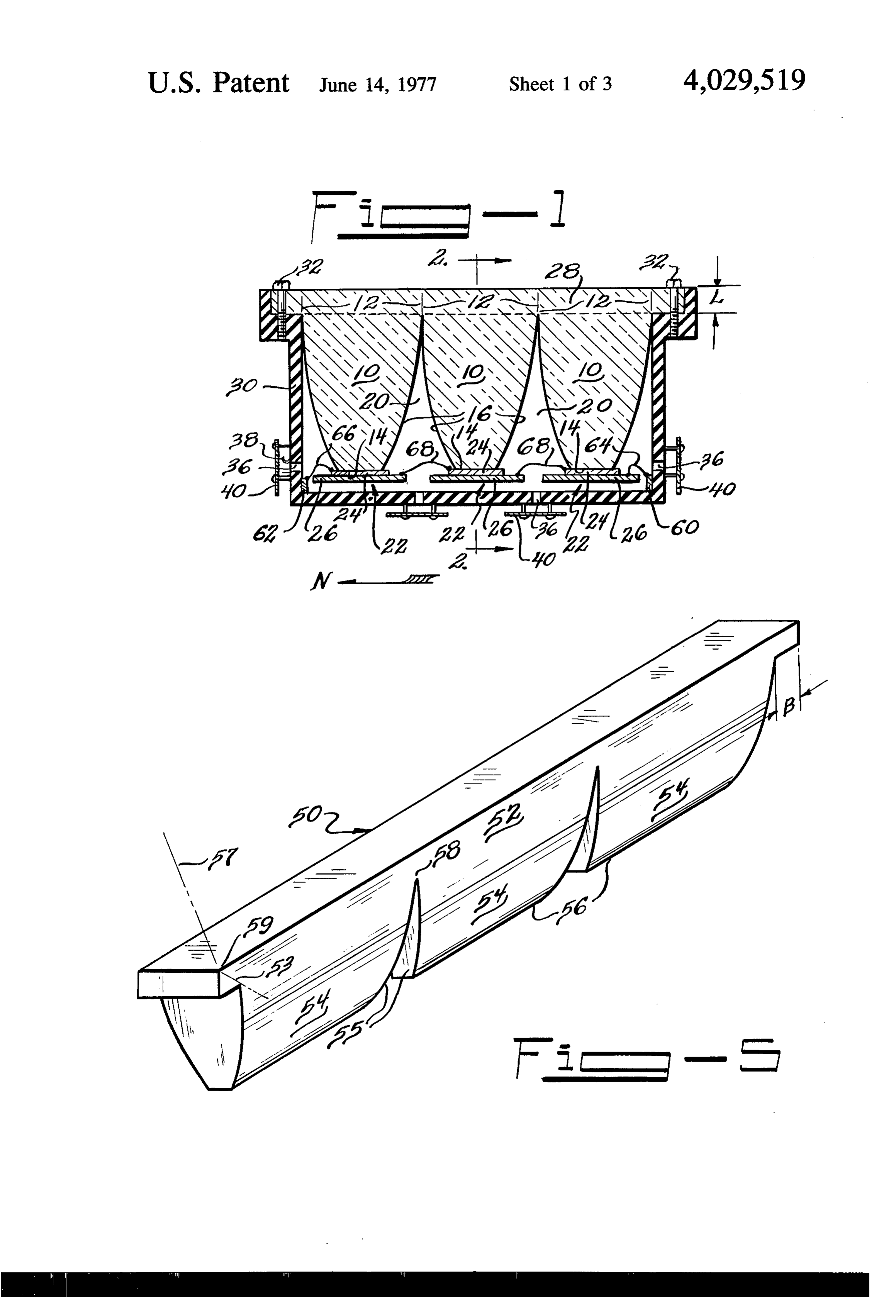
Solar Energy Concentration, Progress Report FIG. 1 is a cross section of one embodiment of the NSF/RANN AER 75-0 1065 (February 1975), in a U.S. invention;
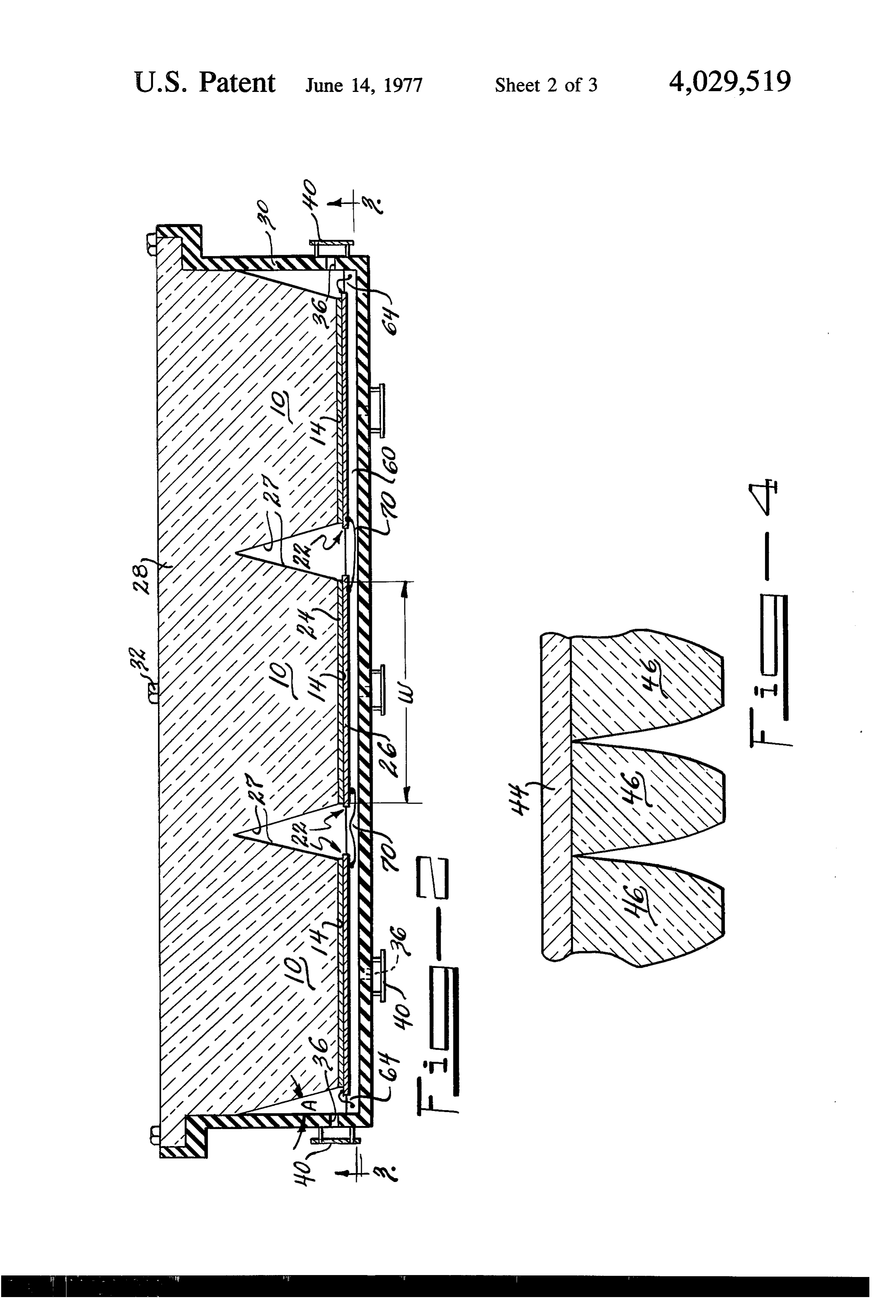
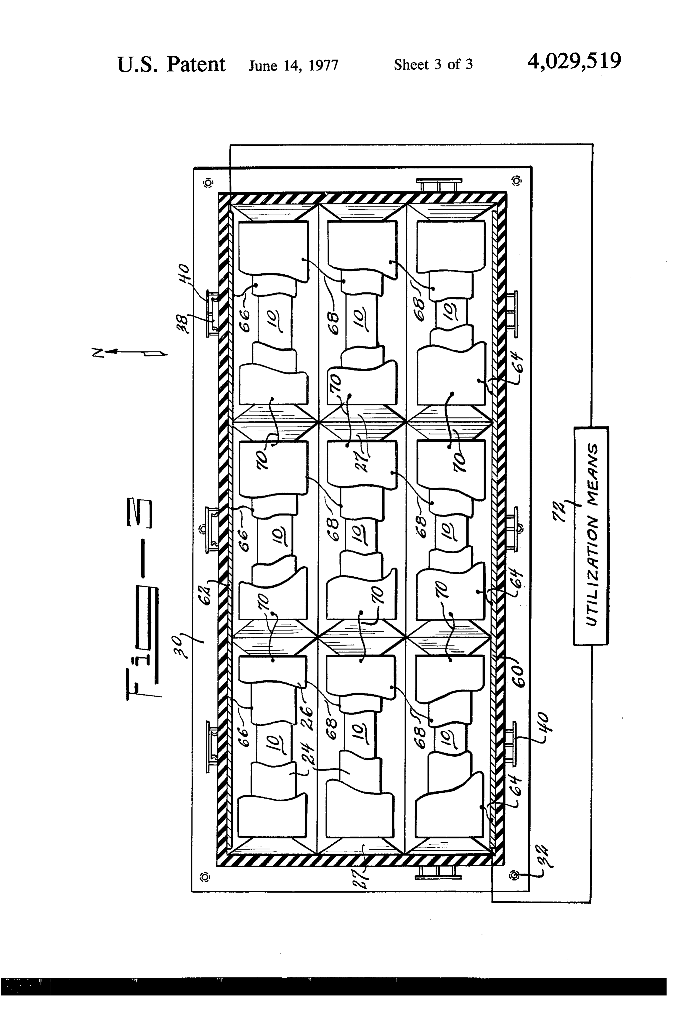
Pat. No. 3,923,381 of Winston and in prior application FIG. 2 is a section through line 2 - 2 of FIG. 1; Ser. No. 581,613 filed May 29, 1975, there are de FIG. 3 is a section through line 3 - 3 of FIG. 2; scribed techniques for generating the ideal side wall FIG. 4 is an alternate embodiment of the assembly of contours for such a collector or transmission device. In medium and cover plate; and a subsequent publication, Applied Optics, Vol. 15, No. 25 FIG. 5 is another alternate embodiment of the assem 2, pages 291-292, February 1976, there is a described bly of medium and cover plate.
the application of the principles disclosed in the above DETALED DESCRIPTION OF THE PREFERRED art relating to ideal reflective side wall contour to trans EMBODIMENT mitting and guiding surfaces at the interface of media of differing indices of refraction for radiant energy. To 30 Referring to FIG. 1, FIG. 2, and FIG.3 there is shown the extent these items contain “essential material' a device for transmitting radiant energy which in the necessary to support the claims hereof or indicate embodiment shown is ideally suited for the concentra background, they are expressly incorporated by refer tion and collection of radiant energy. For such a device ence herein. utilized as a solar energy collector, the cross section of Devices employing these principles include solid 35 FIG. lies in the north-south plane, while the cross dielectric medium. By solid dielectric medium is meant section of FIG. 2 would lie in the east-west plane. The an optically clear material having an index of refraction device utilizes a plurality of solid radiant energy trans at least greater than one. Such media are particularly mission media 10 to direct radiant energy incident at an suited for application with photovoltaic cells and ide entrance area 12 to an exit area 14, where area 12 is ally are configured according to principles contained in 40 larger than area 14. Walls 16 of each medium 10 are of the publication Applied Optics referred to above. The such cross section in the north-south plane, as shown in cells would be positioned at the exit aperture or exit FIG. 1, and the index of refraction of each medium 10 area of the solid medium. The prior art practice has with respect to the external bordering medium 20 is of been to bond the cell to the exit area and then bond the such value that walls 16 operate as energy reflecting cell to a base for the structural support of the assembly 45 and guiding walls. With the appropriate index of refrac of cell and medium. Since the bulk of the solid dielec tion such a medium can be designed to have total inter tric transmission medium is closer to the entrance area nal reflection although such is not required to practice and since the exit area, which is the coupled surface the invention herein disclosed. The ideal cross sections through which structural support is provided, is very are described in the published art previously referred small compared to the entrance area, only a very slight 50 to, such as that in Solar Energy and the issued patent to force is sufficient to break the bond at the exit area end Winston and the application of the ideal wall contour of the assembly, making the assembly of cell and me to solid transmission medium is described in the publi dium very fragile. Further, the differential rates of heat cation in Applied Optics previously referred to. In the cxpansion between the medium and the cell contrib Applied Optics publication the conditions for making utes to the instability of the prior art technique. 55 the medium totally internally reflective of rays incident It is therefore an object of this invention to provide within a given acceptance angle are determined. The an improved radiant energy direction device. medium could also function ideally with the side walls Another object of this invention is to provide an coated with a reflective material. This disclosure is improved radiant energy concentration and collection applicable to either case.
device. () In the embodiment shown, the cross section is ex Another object of this invention is to provide a struc tended parallel to an axis perpendicular to the plane of turally improved solar collector having a solid transmis the cross section to form a trough-shaped structure sion medium and a cover plate. comprised of the solid dielectric. The cross section can SUMMARY OF THE INVENTION also be rotated about an axis to form cone-shaped, solid 65 transmission medium. In any event, the media 10 are
For a radiant energy direction device, having a radi normally provided with an energy transducer 22 posi ant energy transmitting medium defining opposing re tioned at exit aperture 14 for the generation of or the flective surfaces capable of concentrating energy inci absorption of radiant energy. For solar collectors such 6 a transducer would be an energy receiver, a device structural support is provided for the assembly. Since which absorbs energy incident thereon. Energy receiv the entrance area is usually much greater than the exit ers can have a variety of cross sections. For each cross area, there is a greater surface area available for cou section there is a particular preferred contour for side pling of the media 10 to a support means. To allow for walls 16. In the embodiment shown in FIGS. 1 through 5 differential heat expansion of media 10 and transducers 3, the receiver 22 is planar and extends along and is 22, transducers 22 are not coupled to housing 30, but rather float in the external medium 20 which would coincident with area 14. Such a planar receiver might normally be air. Thus, plate 28 by being coupled to be a photovoltaic cell which includes a cell portion 24 responsive to incident energy to develop a voltage medium 10 and housing 30 suspends the array of media 10 in the air. Holes 36 are provided in housing 30 to thereacross and a heat sink portion 26 in electrical 10 allow contact with cell portion 24 for dissipating heat devel air or other coolant fluid to circulate about trans oped by cell 24. The length W of the exit area of each ducers 22 to allow for the removal of heat dissipated medium is tailored to the length of the cells. The cross therefrom.
section in the east-west plane of end walls 27 of each Since the device would normally be tilted so that the medium 10, can have a variety of shapes. These may 15 north end is higher than the south, natural convection either be a straight line end wall, a curved end wall, or will force air through the unit. Of course, artificial a combination of curved and straight line end wall. Cell means for forcing coolant through the unit may also be portion 24 would normally be a semiconductor such as provided. Gutter 38 for the raised north end is provided being primarily of silicon, while sink 26 is preferably a to prevent rain from entering the hole 36 at the north good heat conductor having a rate of heat expansion 20 end. Hole covers 40 for each hole 36 prevent rain and similar to silocon such as copper or steel or Kovar or other splashed material from entering housing 30. In combinations thereof. Heat sink portion 26 is soldered the embodiment of FIGS. 1 through 3, media 10 are to cell portion 24 which, in turn, is coupled to medium integral with plate 28. This assembly lends itself to mass 10. The coupling of cell portion 24 to medium 10 production since plastics may be utilized as media 10. should allow for the transmission of radiant energy 25 plateFor example, the integral unit of media 10 and cover through the coupling. An optically clear epoxy, which 28 can be formed by injection molding. Acrylic is is compatible with the material forming cell portion 24, an ideal material for media 10 and plate 28 and for is satisfactory. injection molding. In the embodiment of FIG. 4 where In the prior art, transducer 22 was bonded to a base 30 cover plate 44 is separate from each medium 46, each which provided the structural support for the assembly medium 46 may be glued to plate 44 to provide the of transducer and medium. The base was then properly necessary structural coupling. Here again an optically oriented so that medium 10 was directed as desired. clear epoxy would be satisfactory to allow radiant en Since the area 14 is ideally much smaller than the area ergy to pass through the coupling. A further embodi 12 to give a large concentration factor, e.g. for use with ment is illustrated in FIG. 5, where rows of elements 50 photovoltaic cells a ratio of entrance area to exit area 35 have a cover plate section 52 and mediums 54 which of 10 to 1 is common, by providing structural support are uniformly made. These rows of elements may be through exit area 14 of medium 10, the resultant as glued together to form the desired array. In FIG. 5, the sembly is very fragile. Because of the narrow support cross section of the row corresponds to the cross sec area of the exit area 14 and the bulk of the assembly tion as described for FIG. 1. Of course, such a row being closer to entrance area 12, the slightest force 40 could correspond to the cross section as described for applied near area 12 would damage and break the With each side wall 16 of ideal contour as described bonding between exit area 14 and cell 22. Because of in the reference publications the maximum concentra the difference in rates of heat expansion of the materi als of medium 10 and the material of cell 24, further tion factor for a trough shaped device is very nearly structural difficulties arise with the assembly. Accord 45 attained. On the other hand, the contribution of the ingly, there is herein described an improved assembly contour of end wall 27 to concentration is small. As the of these elements having greater structural stability. angle of acceptance for each end wall is necessarily A cover plate 28, preferably of the same material as very large a remedial prescription from the ideal con medium 10 and of uniform thickness L, is coupled to tour described in the Applied Optics publication is re medium 10. The cover plate, if separate can also be 50 quired. Such a prescription for a flat receiver involves made of a material having greater ultraviolet absorp combinations of curves and/or straight portions which tion and resistance than the material of medium 10, in extend from the exit area to the cover plate. This is order to further protect medium 10 from degradation shown in FIG. 5 where the end walls 55 extend from the due to the energetic ultraviolet solar photons. As exit area 56 all the way to the bottom of cover plate 52 shown in FIG. 1 and FIG. 2, cover plate 28 is coupled 55 at points 58. Since the end walls make such a small to medium 10 by being fabricated as an integral unit contribution to overall concentration and since extend with medium 10 to form a homogeneous element. As ing such end walls all the way to the cover plate in shown in FIG. 4 cover plate 44 may be coupled to creases fabrication costs, it may be desirable to vary media 46 by having separate elements 46 mounted on end wall contour from the ideal. For example, in FIG. plate 44 such as by glue. Plate 28 is coupled to housing 60 2 the cross section of each end wall 27 is a straight line 30 such as by means of screws 32, with housing 30 so that a V trough is formed between adjacent end completely enclosing the array of media 10. Cover walls. Further, the V trough end walls do not extend all plate 28 serves several purposes. First, it allows radiant the way to the bottom of the cover plate 28. By short energy to pass through it to medium 10 where it is ening the end wall, fabrication costs are reduced. There directed to receiver 22 while at the same time protect 65 exists an angle A that each straight end wall 27 makes ing the medium 10 and receiver 22 from environmental with the vertical which will maximize the concentration factors such as wind, rain, etc. Secondly, as the media factor of such a straight end wall. A is determined by 10 are coupled at entrance area 12 to plate 28, great the following equation:
Page 7scan →
medium are suspended to allow for differential heat
A = 90 - 21sin (11n) expansion therebetween.
where n is the index of refraction of the medium. 2. The device of claim 1 wherein said cover plate is of There also exists an edge effect associated with the 5 beingsame the material as said medium, said cover plate coupled to said medium in such manner that said cover plate. This can be seen in FIG. 5 where the over cover plate and said medium are formed as an integral hang of cover plate 52 is of dimension B. For maximal unit.
concentration, factor B should be large enough so that 3. The device of claim 2 wherein the transverse cross ray 57, incident at the extreme edge 59 of cover plate section of said medium includes opposing side walls 52 and which is refracted along a path 53 determined 10 extending between said exit and entrance areas and by the index of refraction of the medium of cover plate wherein said transverse cross section of said medium is 52, should enter the concentration element 54. If B is extended along an axis perpendicular to said transverse too short, some rays which could be refracted by the cross section to form a trough shaped structure. overhang into medium 54 would not be so refracted. 4. The device of claim 3 wherein said exit surface is When the device is used as a solar concentration 15 device and the transducer is to be a photovoltaic cell, planar and wherein said radiant energy transducer is a radiant energy receiver having a flat surface and posi as illustrated in FIGS. 1 through 3, bus bars 60 and 62 tioned so that said flat surface coincides with said exit are provided. Bus bar 60 is coupled by leads 64 to heat sinks 26 in the row of the array adjacent bus bar 60. 2C2. 5. The device of claim 4 wherein said trough shaped Bus bar 62 is coupled by leads 66 to cell portions 24 in 20 medium the row of the array adjacent to bus bar 62. In rows walls, saidincludes end walls extending between said side perpendicular to these rows all heat sinks are coupled form of a end walls each having a cross section in the by leads 68 to adjacent cell portions, while in the rows away from straight line extending from said exit area the opposing end wall at an angle A with parallel all heat sinks are coupled to the adjacent heat respect to a perpendicular to said exit area, angle A = sinks by leads 70. The bus bars are coupled to utiliza 25 90-2/sin (1/n) with n being the index of refraction of tion means 72 which is capable of utilizing the d.c. the material of said medium. voltage thereby developed. The advantage of the elec trical connection shown is that if one of the photo cells of6.said The device of claim 5 further including a plurality trough shaped media having planar exit areas fail, there will only be a decrease in current rather than a decrease in voltage. 30 and with radiant energy receivers coupled thereto, all It is to be understood the disclosed assembly of ele of said media being of the same material as said cover ments is not limited to trough shaped media, to media plate and being coupled to said cover plate in such with ideal side wall contour, to media having total in manner that said cover plate and said media are formed ternal reflection, or to flat photovoltaic cell receivers. as an integral unit.
The assembly can be utilized with heat absorbing re 35 7. The device of claim 6 wherein said integral unit of ceivers which remove the heat absorbed such as heat cover plate and media is formed as a row of media all pipes or with transducers which generate energy. symmetric about an axis, and wherein said device fur The embodiments of the invention in which an exclu ther includes at least one other integral unit of cover sive property or privilege is claimed are defined as plate and media formed as a row, with said integral follows: 40 units glued together with an optically clear glue. 1. A radiant energy direction device capable of oper 8. The device of claim 6 wherein said housing is in ating in the concentrative mode where energy incident the form of an enclosure surrounding a chamber with on a planar entrance area thereof is directed to an exit said cover plate forming one side of said enclosure and area thereof, comprising: a solid radiant energy trans there being holes in said enclosure to allow air to pass mission medium having surfaces coincident with said 45 from outside said housing to said chamber, said cover entrance and exit areas with the surface coincident plate being mounted on said housing such that said with said entrance area of larger area than the surface media and said radiant energy receivers coupled coincident with said exit area, a cover plate formed of thereto are suspended within said chamber without a solid radiant energy transmission medium to which contacting said housing.
the surface of said medium coincident with said en 50 9. The device of claim 8 wherein said radiant energy trance area is coupled a radiant energy transducer receivers are photovoltaic cells.
coupled to the surface of said medium coincident with 10. The device of claim 9 further including electrical said exit area, and a housing upon which said cover connections coupledck to ksaid> cells.
plate is mounted such that said transducer and said
Provenance
- Collection
- Patents citing this work
- Pages
- 7
- Method
- pdftotext (the PDF's own text layer) + pdftoppm 300dpi page scans
- Patent office record
- patents.google.com →
- Source
- Google Patents citing-documents table
- Assignee
- The United States Of America As Represented By The United States Energy Research And Development Administration
- Published
- 1977-06-14
- Transcribed from
- patentimages.storage.googleapis.com →