

patent · US4520795A
Solar collector having tank and glazing construction
4 June 1985
Text
Page 1bibliographic recordscan →
United States Patent (19)
Parkyn et al.
SOLAR COLLECTOR HAVING TANK AND
GLAZING CONSTRUCTION
Inventors: William A. Parkyn; Horace W. Ladd;
Andrew M. Mellon, all of 1424 W.
259th St., Harbor City, Calif. 90710
51 Int. Cl. ................................................. F24J 3/02 (52) U.S.C. ..................................... 126/443; 126/437 Field of Search ........................ 126/443, 437, 438
2,247,830 7/1941 Abbot .................................. 26/443 3,987,781 10/1976 Nozik et al. .. ... 126/443 4,048,982 9/1977 Pei ................ ... 126/442 4,081,289 3/1978 Campbell ............................ 126/443
4, 19,085 10/1978 Knowles et al. .................... 126/433 4,124,019 11/1978 Heffelfinger ......... ... 126/443 4,134,388 1/1979 Kersten et al. ... ... 126/443 4,306,544 12/1981 Clemens ........... ... 126/434 4,416,257 11/1983 Bale ..................................... 26/443 Primary Examiner-Carroll B. Dority, Jr.
Attorney, Agent, or Firm-William W. Haefliger
Apparatus for integral collection and storage of solar thermal energy, comprises (a) a relatively large storage vessel having side and end walls that absorb solar energy in order to heat its contents;
(b) a translucent enclosure surrounding the large stor age vessel, for suppression of convective heat losses; (c) structure on the vessel for the suppression of thermal radiation heat losses from said large storage vessel; the apparatus providing a ratio of thermal mass, as mea sured in BTU per degree Fahrenheit, to heat-loss coefficient, as measured in BTU per degree Fahren heit per hour, exceeding 36 hours.
24 Claims, 6 Drawing Figures
Drawings
Page 2drawing sheetscan →
Page 3drawing sheetscan →
Page 4scan →
Solar collector having tank and drawing description
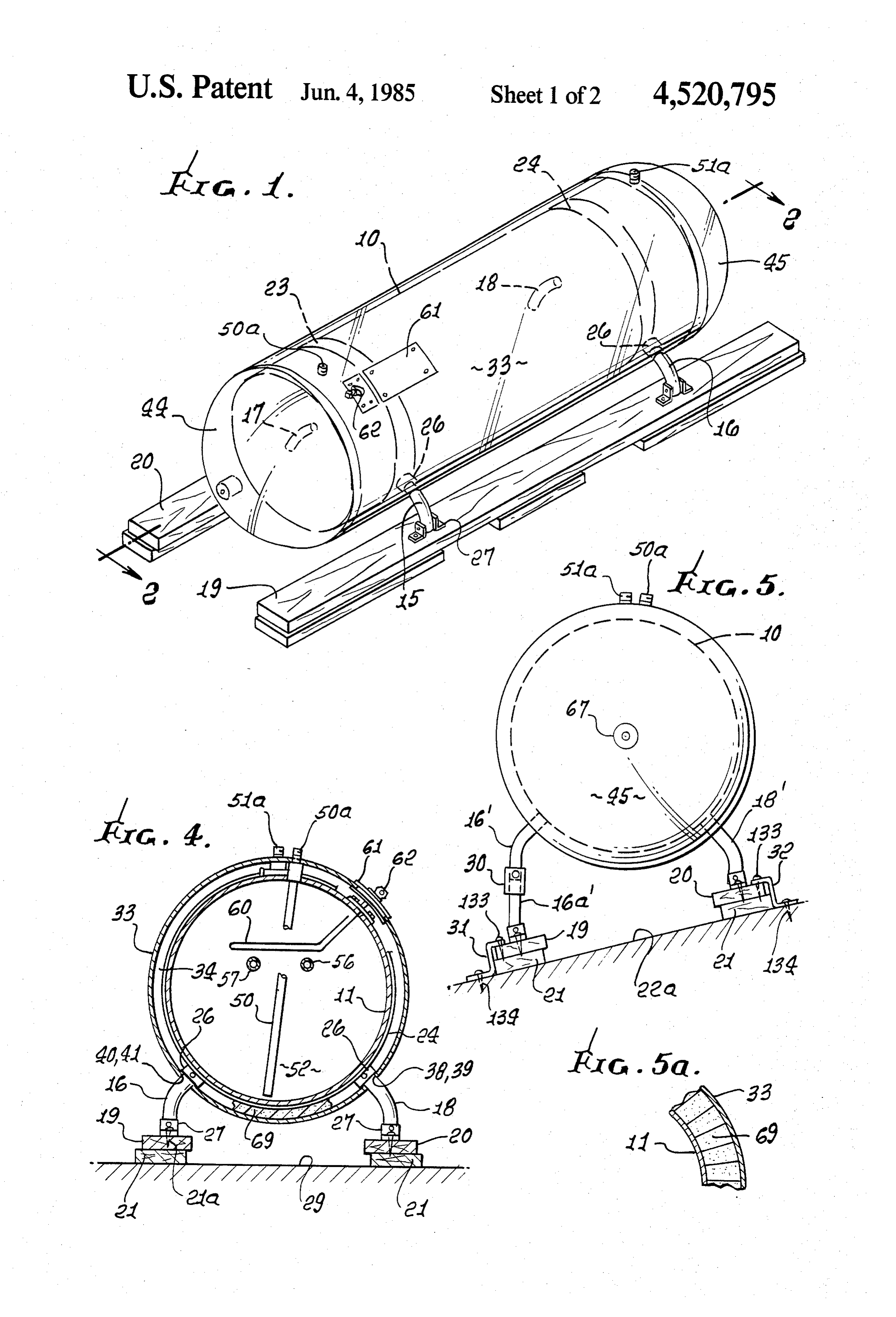
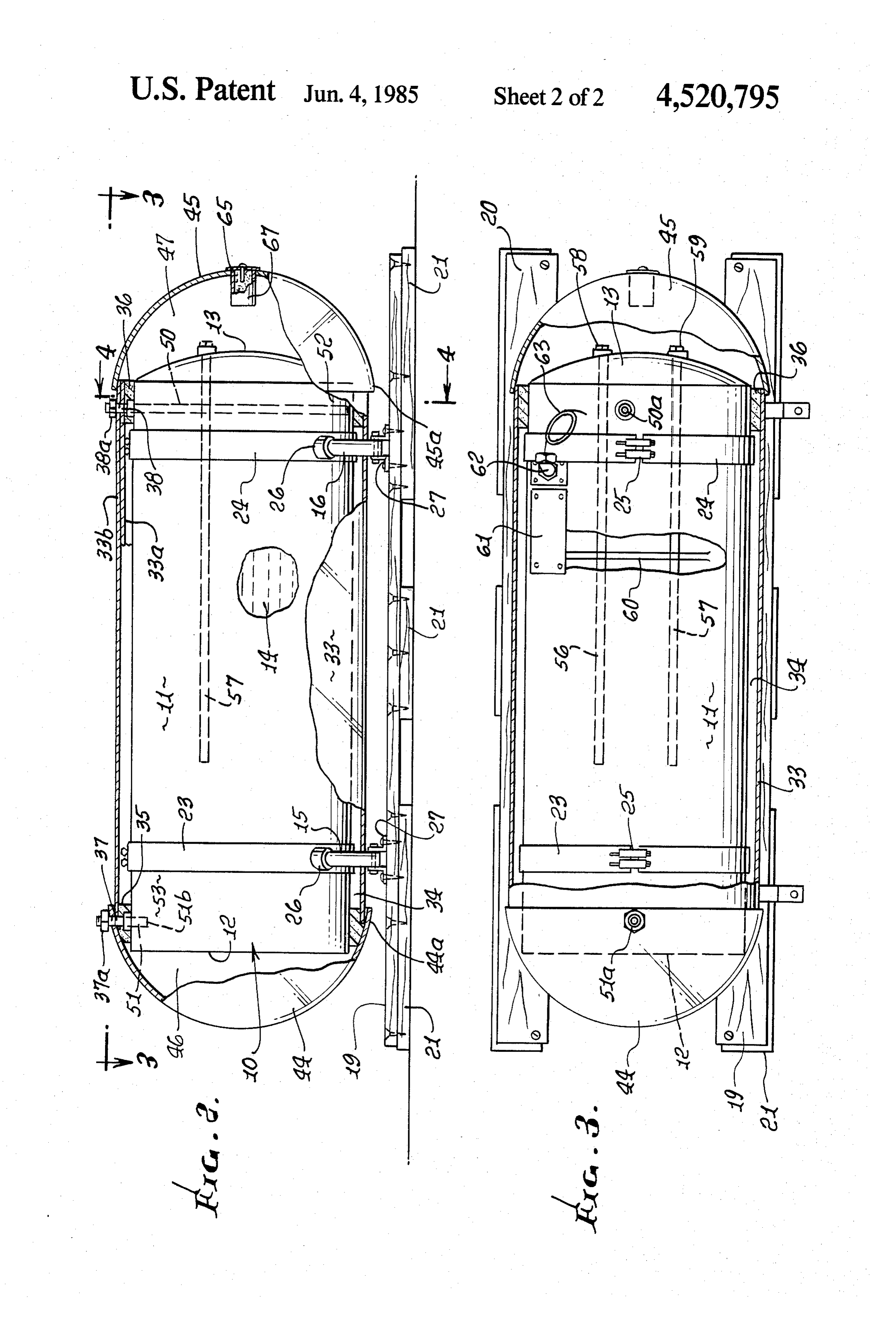
GLAZING CONSTRUCTION FIG. 1 is a perspective view of solar collector appara tus incorporating the invention;
BACKGROUND OF THE INVENTION 5 FIG. 2 is an elevation taken in section on lines 2-2 of This invention relates generally to collection and FIG. 1;
Storage of solar thermal energy. More particularly, it FIG. 3 is a plan view on lines 3-3 of FIG. 2; concerns highly effective and improved apparatus for 2; FIG. 4 is a section in elevation on lines 4-4 of FIG. collecting and storing such energy in the form of mass O FIG. 5 is an end view of modified apparatus; and with its temperature elevated above that of its surround FIG. 5a is a fragmentary showing of a modified glaz ings. ing-tank wall assembly.
There is clearly a need for compact, easily con structed and efficient apparatus of the above referenced DETAILED DESCRIPTION type; in particular, there is a requirement for such appa 15 In the drawings, a container or tank 10 is provided to ratus characterized by a high thermal mass in relation to receive liquid (as for example water) to be heated by its heat loss coefficient, i.e. BTU per degree Fahrenheit transfer of heat from the tank wall on which solar radia per hour. It is particularly desirable that the apparatus tion impinges. The tank is typically metallic, and has a have a construction enabling attainment of such ratios cylindrical side wall 11 which is longitudinally elon (thermal mass/heat loss coefficient) in excess of 24. It is 20 gated, and two opposite end walls 12 and 13. Wall 13 also desirable that the apparatus be easily transportable may be shallowly outwardly convex, as shown. Liquid to a use site, and then finally assembled as by attachment in the tank appears at 14.
of translucent shell components to liquid storing tank Tank support means is provided to include leg struc structure that is sturdily supported by load distributing 25 ture projecting away from the tank wall 11, and in a means, so as to be mounted on roofs, for example. downward direction or directions. In the example, the Known prior apparatus did not afford the above advan leg structure includes multiple legs 15-18 supported by tages or their combination, as in the unusually advanta skid means. The latter is shown to include two longitu geous structures now made possible by the present in dinally elongated and generally parallel wooden skids vention. 19 and 20. Skid 19 supports legs 15 and 16, and skid 20 30 supports legs 17 and 18. Wooden blocks 21 are attached
SUMMARY OF THE INVENTION as by fasteners 21a to the underside of the skids for It is a major object of the invention to provide highly attachment to or support on roof structure indicated at efficient apparatus for collecting and absorbing solar 22The in FIG. 4.
radiant energy, and retention of thermal energy, and 35 such astank support structure also includes band means, metallic bands 23 and 24 wrapped or stretched characterized by the advantages referred to above. about the tank side wall, band connection being shown Basically, the apparatus comprises at 25. The upper ends of the legs are attached to the (a) a metal tank which absorbs solar radiant energy and bands, as via sockets 26 integral with the bands and transfers heat to liquid in the tank, the tank having a receiving the legs. The lower ends of the legs are at side wall and a first end wall, 40 tached to the skids, as via brackets 27; thus, the legs may (b) tank support means including leg structure project be inserted into the sockets and attached to the skids at ing away from the tank for supporting same, and the job or installation site. Note that legs 16 and 18 of (c) translucent glazing shell means supported by the one pair diverge relatively downward, in FIG. 4, as do tank and having a side wall extending about and legs 15 and 17 of the other pair, whereby the skids are spaced from the tank side wall, the shell means in 45 sufficiently spaced apart to support the tank even dur cluding at least one dome in alignment with said tank ing rocking of the roof, as during an earth quake. end wall and spaced therefrom, said shell means In the modification shown in FIG. 5, the leg 18' is adapted to pass radiant solar energy to impinge on the shorter than the overall leg 16" and 16a'; and leg 16a' is tank side wall and end wall. an extension coupled at 30 to leg 16'. This better accom As will be seen, the leg structure may extend from the 50 modates the support of the tank to the inclined roof 22a, tank through the shell side wall, and may include multi whereby skid 19 is lower and further from the tank 10 ple legs carried by load distributing skid means, such as than skid 20. Brackets 31 and 32 engage the skids and two elongated skids which are easily located and sup the roof, and are attached thereto as by fasteners 133 portable on building roof structures. Bands may be and 134, to further stabilize the installation. In accordance with a further aspect of the invention extended around the tank to provide connection of the 55 translucent legs to the tank, the bands located in the zone or space glazing shell means is provided to be sup between the tank and the surrounding translucent shell. ported by the tank, and to be installable at the job site. The shell means is adapted to pass radiant solar energy
Further, the shell domes may be attached to the shell to impinge on the tank side wall, and one or both end side wall ends, to extend at opposite ends of the heavy 60 walls, for heating those walls which then conduct heat tank, for optimizing collection of solar radiation to the liquid thereby providing a "greenhouse' zone of maximum ple, includesina the tank. Such shell means, in the exam shell side wall 33 extending annularly extent, around the tank. (Heat losses are thereby inhib about and spaced from the tank side wall, to provide a ited or suppressed in a simple effective manner.) trapped air space or zone 34 therebetween, for "green These and other objects and advantages of the inven 65 house' heating effect. The shell side wall may comprise tion, as well as the details of an illustrative embodiment, a panel or sheet of plastic material (acrylic for example), will be more fully understood from the following de formed or bent in a circularly curved path to fit over scription and drawings, in which: spacer rings 35 and 36 attached to the tank side wall (see
Page 5scan →
FIGS. 2 and 3). The panel may have edge portions that magnify the apparent size of the vessel to thereby in overlap as at 33a and 33b, and held in that condition by crease its collection of thermal energy. One such liquid fasteners 37 and 38 protruding from the support rings. is glycerine, and one such gel is knox gelatine. Space 34 The shanks of the fasteners may be threaded to receive may alternatively be a vacuum. hold-down nuts 37a and 38a. Vessel 10 may alternatively be spherical; and the The panel 33 also contains openings 38-41 to closely thermal radiation suppression means may consist of a pass or receive the legs, inserted through the panel and coating on the interior surface of the glazing, which into the sockets 26, as at the job site. coating is transparent to Solar radiation and reflective to The shell means includes at least one dome in align thermal infrared radiation.
ment with a tank end wall and spaced therefrom. In the 10 The advantages of this invention, are to be contrasted example, two such domes 44 and 45 are provided, re with the prior art of solar heating of fluids which gener spectively in alignment with tank end walls 12 and 13, ally falls into two major categories, depending whether and spaced therefrom, as at 46 and 47, adding to "green the functions of solar energy collection and storage are house' heating effect. Note that sunlight from all direc separate or combined. Furthermore, both types gener tions may therefore pass through the shell structure 33, 15 ally employ planar transparent apertures for admission 44 and 45 to impinge on the tank walls 11, 12 and 13, for of solar energy to an absorbing means, so that they maximum heating efficiency. The domes may also be collect energy only when the sun is in the part of the sky formed of plastic material (such as acrylic), and they which they are facing.
have annular rims or rim portions 44a and 45a that are Separation of the functions of collection and storage mounted telescopically to the annular ends of the shell allow the respective separate apparatus to be optimized side wall 33. Spacer rings 35 and 36 may be located to without compromise, but entail disadvantages as well. support the ends of the panel 33, as well as the rims of The total apparatus is inherently more complex and the domes, as shown. The attachment of the dome rims expensive, and less reliable. In order to transfer the to the panel or side wall 33 ends may be further secured, collected solar thermal energy to the storage means, the as by adhesive bonding, using epoxide cement, for ex 25 collection means must operate at a temperature above ample. that of the storage, and hence have greater heat losses Also shown are a cold water inlet duct 50 and an and less efficiency. Furthermore, the collection means outlet duct 51. Both ducts open at the top of the tank needs time in the morning to warm up to the necessary and shell (see 50a and 51a); however duct 50 opens to operating temperature, thereby cutting down the hours the lower interior 52 of the tank at one end thereof, 30 of operation and allowing the warm-up heat to be lost at whereas duct 51 is elongated and opens at 51b to the night.
upper interior 53 of the tank at the opposite end thereof. Combining the functions of collection and storage Sacrificial anode elements 56 and 57 are attached at 58 allows considerable simplification of the apparatus, and 59 to the tank end wall 13, to extend lengthwise increasing its reliability and decreasing its expense. within the tank interior. An electrical heater element 60 35 Such systems typically lose a large part of their stored extends in the tank interior, and is energizable to heat solar heat in one night. Moreover, the sunlight entering water therein, as a back-up heater means. An access the planar aperture must be directed onto the surface of plate 61 on the tank exterior supports a duct 62 for the storage vessel. This is usually done with curved external electrical wiring 63 that connects to the heater mirrors mounted on the back wall of a large box con element. Numeral 67 indicates a receptacle for a des 40 taining the storage vessel and having one wall transpar sicator 65 exposed to the space or zone between the ent to admit sunlight. The box is much bigger than the tank wall and glazing shell structure, to absorb moisture vessel, giving rise to strong convection in the air inside and prevent fogging of the shell. The dome 45 may be it. Practical limitations on the box size give concomitant removable, to provide access to the dessicant, for re limits on the size of the storage vessel. placement. 45 The present invention is of the combined type, in that The invention offers a highly efficient apparatus for it has a storage vessel to be directly heated by sunlight. collecting and storing solar energy, and which is easily An important difference from the prior art lies in the transported and assembled at a job site. Also, the con fact that the vessel is entirely surrounded by translucent Struction enables the ratio of thermal mass to heat loss walls, so that its entire external surface can receive solar coefficient (BTU/F/hour) to be very high (over 36 50 radiation. There are several advantages to this feature. hours) which greatly increases efficiency in terms of First, since at least 30% of sunlight is diffuse (coming low heat loss. from the entire sky), the vessel's light-gathering ability The surface of the tank may be darkened, as by a is enhanced. Second, instead of expensive mirrors, the nickel coating (product "MAXOR B' of International apparatus can use the sunlight reflected from adjacent Nickel Co.) to reduce heat radiation losses, at night. 55 white-painted surfaces, which are much cheaper and The space between the glazing and tank may contain more effective than mirrors. Third, spacing the trans cellular or honeycomb material oriented to pass solar parent enclosure close to the storage vessel causes the radiation therethrough, to further increase efficiency. convective heat losses to be much smaller than those of See a portion of said material indicated at 69 in FIG. 5a. a vessel in a large box, both because of the smaller outer Typically, the steel tank may be at least about 5 feet 60 surface area for heat losses and because of the smaller long, and at least about 1 to 2 feet in diameter, for volume of interior air giving weaker convective heat optimum efficiency. If the tank contains for example losses. Given practical constraints on the overall size of 120 gallons of water, and up to 30 gallons of water are a solar heater, the apparatus of the invention can devote used in a day (as in dwellings) the tank water remains a much greater portion of its volume to it storage vessel, hot. 65 giving greater heat-storage capacity. Space 34 may be filled with a transparent liquid or a A second important advantage lies in the relation gel which both suppresses convective and radioactive between storage capacity and heat losses. Whenever the heat losses and, because of its index of refraction, acts to storage temperature is above that of the surroundings, 6 heat will be lost in proportion to that temperature dif 2. In apparatus for collecting and absorbing solar ference, The proportionality constant is called the heat radiant energy, for storing same, the combination com loss-coefficient, and can be measured in BTU per de prising gree Fahrenheit per hour. When there is no sunlight to (a) a metal tank which absorbs solar radiant energy heat the storage vessel, a fixed proportion of its stored 5 and transfers heat to liquid in the tank, the tank heat will be lost every hour. The thermal capacity, or having a side wall and a first end wall, thermal mass, of the storage vessel is the product of its (b) tank support means including leg structure pro mass and its specific heat. Since the specific heat of jecting away from the tank for supporting same, water is one, a vessel filled with 1000 pounds of water and will have a thermal mass of 1000 BTU per degree Fahr- 10 (c) translucent glazing shell means supported by the enheit. When the heat-loss coefficient is divided into the tank and having a side wall extending about and thermal mass, the result is a characteristic time, during spaced from the tank side wall, the shell means which the stored heat exponentially decays to (about including at least one dome in alingment with said 36%) of its original value. If this thermal decay time is tank end wall and spaced therefrom, said shell 36 hours or more, then in a 12-hour night only 18% or means adapted to pass radiant solar energy to im less of the stored heat will be lost, assuring heat delivery pinge on the tank side wall and end wall, in the morning. (d) said leg structure extending through said shell side There are several further advantages to a larger stor wall.
age vessel than was customary in the prior art. In the 3. The combination of claim 2 wherein said support case of solar water heating, the daily draw of hot water 20 means includes skid means supporting said leg structure. becomes a smaller portion of the storage capacity as the 4. The combination of claim 3 wherein: vessel is enlarged. The heat remaining the next day will (i) said leg structure includes multiple legs, augment the heat to be collected. Thus even in poor (ii) said skid means includes skids supporting said legs weather, several days heat can be accumulated in a 25 and elongated in the direction of tank and shell side large vessel having a long thermal decay time. Another wall elongation.
advantage is that solar heat tends to be concentrated at meansThe 5. combination of claim 2 wherein said support includes band means extending about the tank the top of the storage vessel by convection currents side within the enclosed liquid. This means that the upper wall wall and within a zone defined between the shell side tank side wall, the leg means attached to said most portions of the enclosed liquid will heat up rap 30 band means within said zone. idly.
6. The combination of claim 4 wherein
Another feature of the invention is the provision of (iii) said support means also includes two bands ex substantially horizontal area at the top of the storage tending about the tank side wall within a zone vessel, which would receive the greatest portion of the defined between the shell side wall and the tank Solar energy striking the vessel, further adding to the 35 side wall, rapid heating of the top portions of the stored liquid. (iv) first and second of said legs attached to one band, A final feature is suppression of thermal radiation and third and fourth of said legs attached to the heat losses, which combine with the reduction in con other band, vective heat losses to give a low overall heat-loss coeffi (v) the first and third legs attached to one skid, and cient and hence a long thermal decay time. This radia- 40 the second and fourth legs attached to the other tion suppression can be accomplished by suitable coat skid.
ings either on the outer wall of the storage vessel or on 7. The combination of claim 4 wherein there are two the inner surface of the translucent enclosure. Another of said skids spaced at substantially equal distances from means is the use of translucent honeycomb, which sup the tank, there being pairs of said legs, the legs of each presses radiation as well as convection. 45 pair diverging downwardly and respectively connected This invention, because of its simplicity and effective with said two skids.
ness, can in mass production be made for about the same 8. The combination of claim 4 wherein there are two cost as conventional gas-fired and electric water heat of said skids, and pairs of said legs, the legs of said pairs etS.
We claim: 50 respectively connected with the two skids, one leg of 1. In apparatus for collecting and absorbing solar pair each such pair being shorter than the other leg of said radiant energy, for storing same, the combination com the other so that one skid is located closer to said tank than prising energy skid, along the skid lengths, the skids extend ing in generally parallel relation.
(a) metal tank which absorbs solar radiant and trans 9. The combination of claim 2 wherein the tank has a fers heat to liquid in the tank, the tank having a side 55 second end wall, the shell means including a second wall and a first end wall, (b) tank support means including leg structure pro dome in alignment with said tank second end wall and spaced therefrom, said tank side wall having opposite jecting away from the tank for supporting same, annular end portions, the domes having annular rims and extending in telescopic relation with said side wall an (c) translucent glazing shell means supported by the 60 nular end portions, respectively.
tank and having a side wall extending about and 10. The combination of claim 2 including spacer spaced from the tank side wall, the shell means means on the tank, the shell side wall supported on said including at least one dome in alignment with said spacer means, to pass said leg structures through open tank end wall and spaced therefrom, said shell ings in the shell side wall.
means adapted to pass radiant solar energy to im- 65 11. The combination of claim 1 including inlet and pinge on the tank side wall and end wall, outlet ducts passing through the tank wall and said (d) said leg structure extending through at least one glazing shell means, and communicating with spaced opening defined by the shell means. apart tank interior regions.
Page 7scan →
12. The combination of claim 1 having a thermal mass (a) relatively large storage vessel having side and end to heat loss coefficient ratio of at least 24 hours. walls that absorb solar energy in order to heat its 13. In apparatus for integral collection and storage of contents;
solar thermal energy, the combination comprising (b) translucent enclosing means surrounding said (a) relatively large storage vessel having side and end 5 large storage vessel, for suppression of convective walls that absorbs solar energy in order to heat its heat losses; said transparent enclosing means com contents;
prising- a single surrounding translucent surface (b) translucent enclosing means surrounding said which is substantially parallel to the exterior of said large storage vessel, and close enough to it so as to large storage vessel, for suppression of convective 10 cause reduction in convective heat losses, together heat losses; and wherein said transparent enclosing with multiple transparent walls extending perpen means consists of a single surrounding translucent dicularly from the exterior of said large storage surface which is substantially parallel to the exte vessel to said transparent enclosing surface, and rior of said large storage vessel, and close enough forming closed cells of sufficiently high aspect to it so as to cause reduction in convective heat 15 ratio for suppression of convection in the air within losses, them, with said multiple walls having high solar (c) said apparatus having a ratio of thermal mass, as transparency and high absorptance of thermal in measured in BTU per degree Fahrenheit, to heat frared radiation, so as to suppress thermal radiation loss coefficient, as measured in BTU per degree 20 (c)heat said losses from storage vessel, apparatus having a ratio of thermal mass, as
Fahrenheit per hour, exceeding 36 hours, measured in BTU per degree Fahrenheit, to heat (d) the space between the exterior of said large vessel loss coefficient, as measured in BTU per degree and said translucent surface filled with a transpar Fahrenheit per hour, exceeding 36 hours. ent liquid or gel which both suppresses convective 18. The combination of claim 4 wherein the space and radiative heat losses and, because of its index of 25 between the exterior of said large storage vessel and refraction, acts to magnify the apparent size of said said transparent surface is a vacuum. vessel and thereby increase its collection of solar 19. The combination of claim 1 including thermal energy. radiation suppression means which consists of a coating 14. The combination of claim 13 wherein said large on the exterior of said tank which has high absorptance storage vessel has sufficient vertical extend for sunlight 30 of solar radiation and low emittance of thermal infrared to cause thermal stratification whenever its contents are radiation.
a liquid. 20. The combination of claim 2 including thermal 15. The combination of claim 13 wherein said large radiation suppression means which consists of a coating storage vessel has sufficient top area of substantially 35 on the interior of said translucent shell means which is transparent of solar radiation and reflective to thermal horizontal orientation to cause sunlight to rapidly heat infrared up the uppermost contents of the vessel. radiation.
16. The combination of claim 13 wherein said trans 21. The combination of claim 13 wherein said large parent enclosing means consists of multiple surrounding storage vessel has an outwardly domed surface. 22. The combination of claim 1 wherein said tank is a translucent surfaces which are substantially parallel to 40 vertically oriented cylinder.
the exterior of said large storage vessel, and spaced 23. The combination of claim 1 wherein said tank is a closely enough so as to cause reduction in convective horizontally oriented cylinder. heat losses. 24. The combination of claim 1 wherein an electrical 17. In apparatus for integral collection and storage of backup heater is installed in said tank. solar thermal energy, the combination comprising 45 ck k k ck
Provenance
- Collection
- Patents citing this work
- Pages
- 7
- Method
- pdftotext (the PDF's own text layer) + pdftoppm 300dpi page scans
- Patent office record
- patents.google.com →
- Source
- Google Patents citing-documents table
- Assignee
- Parkyn William A
- Published
- 1985-06-04
- Transcribed from
- patentimages.storage.googleapis.com →