

patent · US4031421A
Electric generator
21 June 1977
Text
Page 1bibliographic recordscan →
United States Patent (19)
Geiger
54 ELECTRIC GENERATOR
Inventor: Otto Geiger, Schwabach, Germany (73) Assignee: GeSig Energietechnik GmbH,
Schwabach, Germany
(30) Foreign Application Priority Data
U.S. C. ................................ 310/112; 310/114 5ll Int. Cl........................... . . . . . . . . . . . . H02K 19/34
UNITED STATES PATENTS
3,374,376 3/1968 Kromrey ............................ 310/112 3,396,296 8/1960 Esters .............................. 31046 X 3,426,224 2/1969 Esters .................................. 310,41 3,510,699 5/1970 Fredrickson ... . 310/114 X 3,535,572 10/1970 De Rugeris..... . 310/114 X 3,603,823 9/1971 Mason ........................... 310/112 X
3,713,015 l/1973 Frister ........................... 310/114 X Primary Examiner-Donovan F. Duggan
Attorney, Agent, or Firm-Allison C. Collard
Electric generators having a rotor on a shaft and a stator, both carrying peripherally successive poles that have a substantially uniform angular distance or pole step therebetween, with at least one pair of electrically identical but separate, axially aligned generator sec tions that include pole cores that occupy substantially the same sectors as the gaps between them, and wherein the angular position of the rotor shaft, in which the poles overlap between the rotor and the stator of the same generator section, is offset for both sections by half the angular distance between the poles. Prefer ably at least one group of radially mounted, and at least one group of axially mounted, pole pairs os provided in both the rotor and the stator. Preferred exemplary embodiments are disclosed.
12 Claims, 10 Drawing Figures
Drawings
Page 2drawing sheetscan →
Page 3drawing sheetscan →
Page 4drawing sheetscan →
Page 5drawing sheetscan →
Page 6drawing sheetscan →
Page 7drawing sheetscan →
Page 8drawing sheetscan →
Page 9drawing sheetscan →
Page 10scan →
least two sections that are both mounted on the shaft,
ELECTRIC GENERATOR fitted on both sides with the axially mounted pole pairs, and on their peripheries with the radially mounted pole
This invention relates to an electric generator having pairs.
a rotor and a stator, carrying respective, peripherally The generator can be fitted with a cover, consisting successive poles that have a substantially uniform angu of two or more sections that adjoin, and may have lar distance therebetween. mating terminal or edge portions that allow interen In such generators efficiency is usually impaired in gagement between them. The pole pairs can be partly that the inductive current flows so that its magnetic installed on the cover sections.
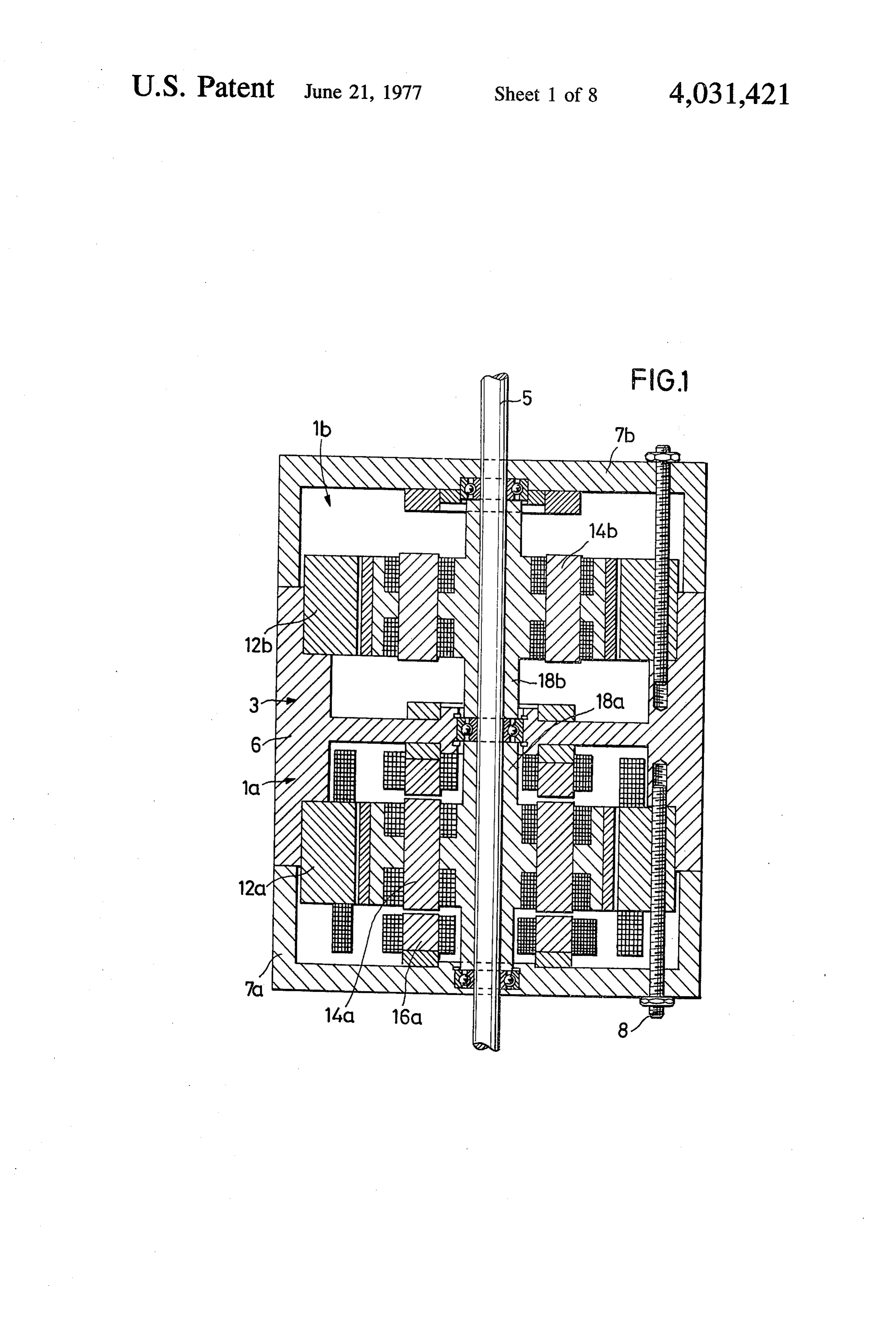
field inhibits the conditional change by which the cur 10 The invention will now be more fully explained, to rent was generated, as a result of which the rotation of gether with further objects and many of the attendant the rotor with respect to the stator is counteracted. It is advantages, and it will be readily appreciated as the however just this rotation, resulting from outsie energy same becomes better understood by reference to the supply, that causes the inductive current to be pro following detailed description, when considered with duced. If one can reduce or neutralize this handicap, 15 the accompanying drawings wherein generally defined as the resultant field braking effect, FIG. 1 is a schematic longitudinal section of an exem the efficiency of such generators can be substantially plary inventive generator embodiment, having two improved. generator sections;
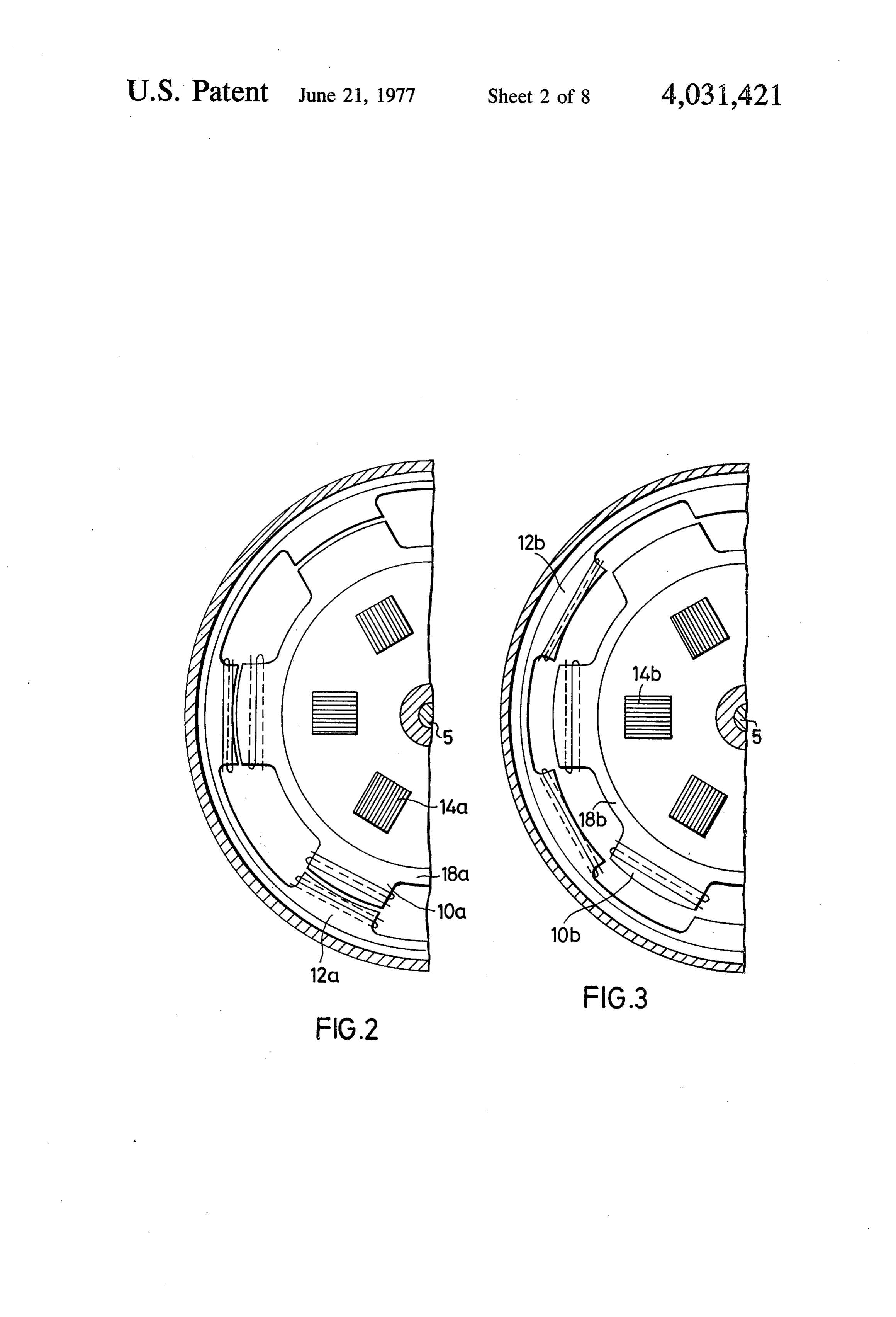
It is therefore one of the objects of this invention to FIGS. 2 and 3 are respective, horizontal sections provide a high-efficiency generator, yet of a simple 20 through the lower and the upper generator sections of structure, by eliminating or neutralizing the resultant FIG. 1, identical angular positions of a common rotor field braking effect that impairs the efficiency. Addi shaft being shown;
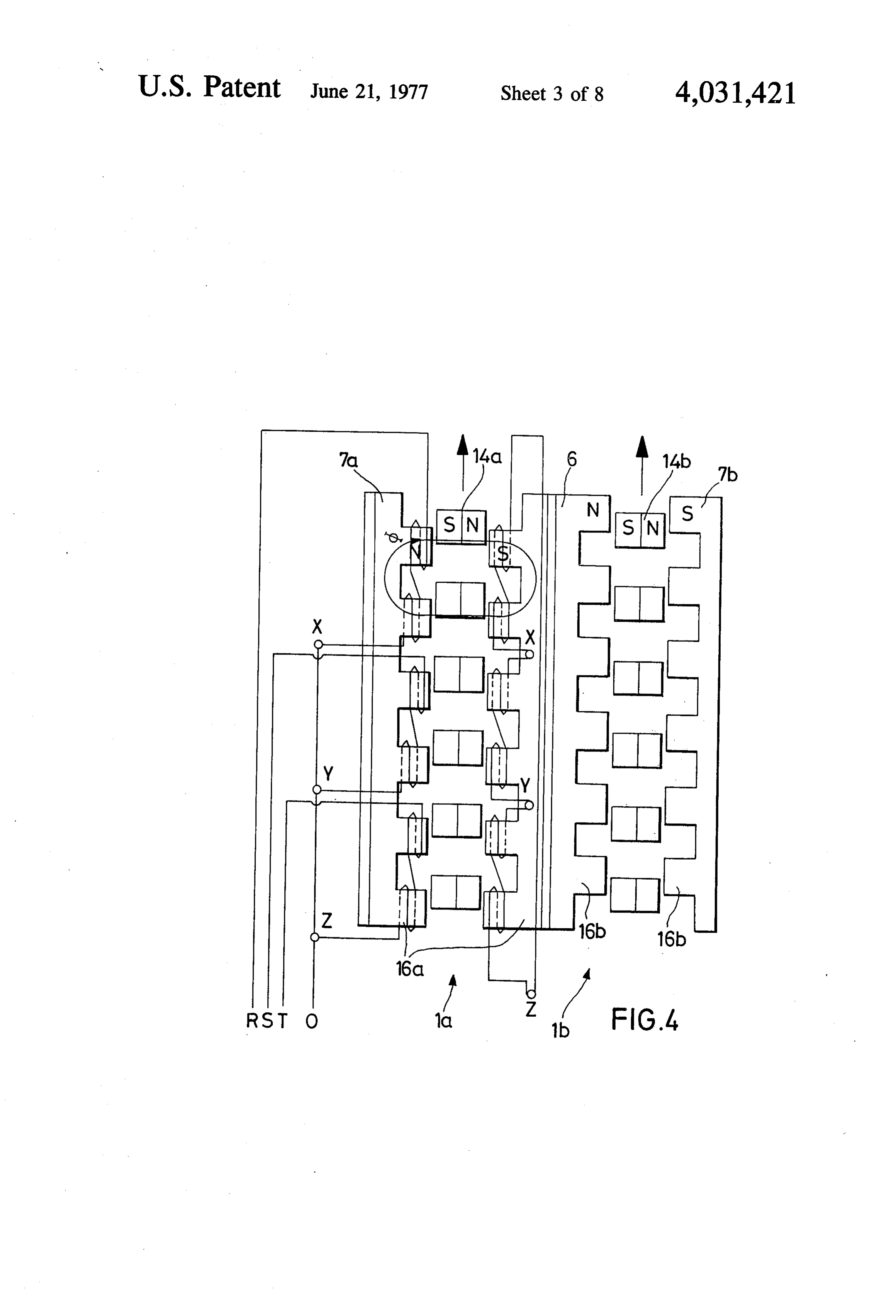
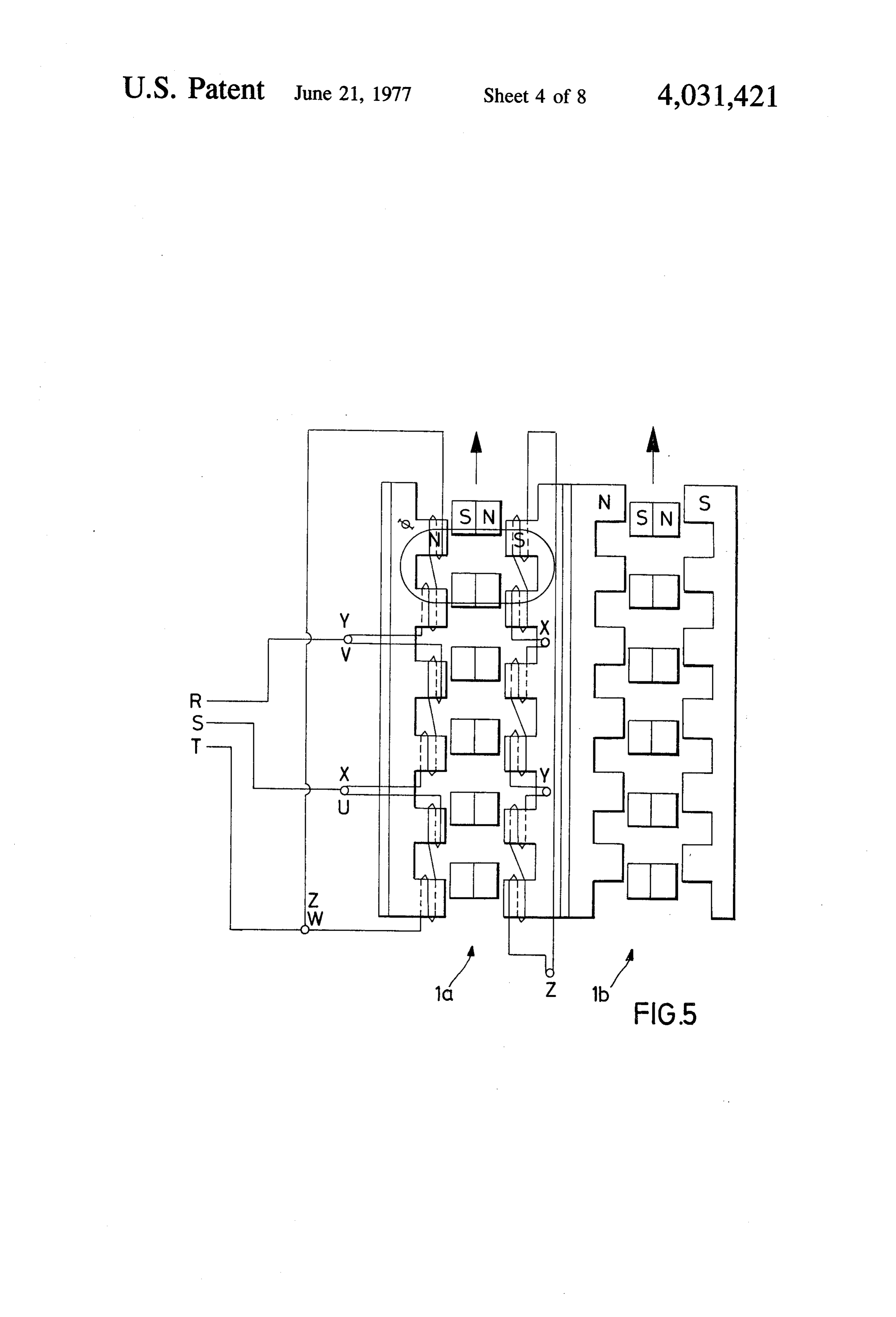
tionally the invention has as its object to use magnet FIGS. 4 and 5 are schematic developments of axially poles with maximum saturation, without a surplus in arranged generator poles according to FIGS. 1 to 3, rotary energy. 25 showing windings of the stator poles in star and delta Economic considerations are to be increased further connections, respectively;
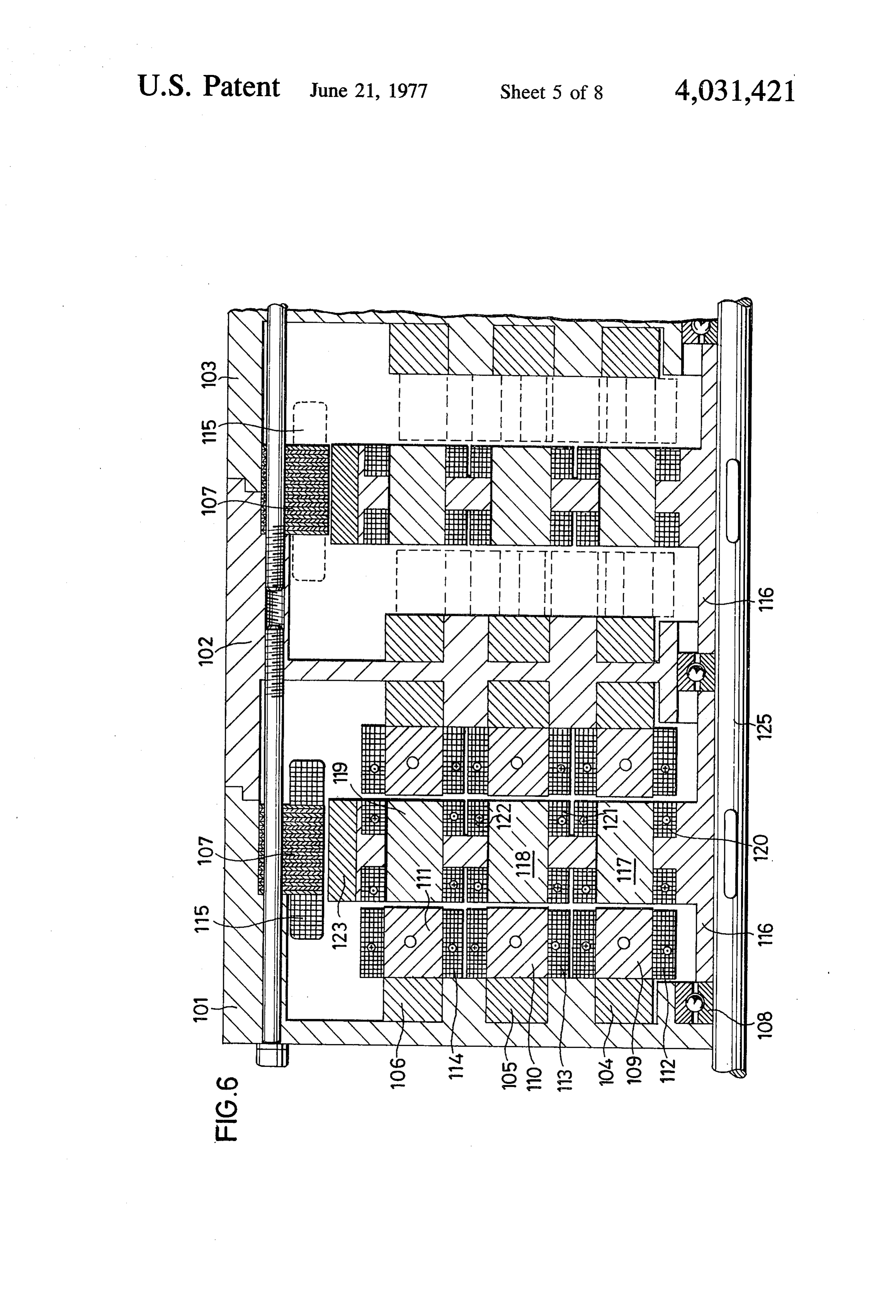
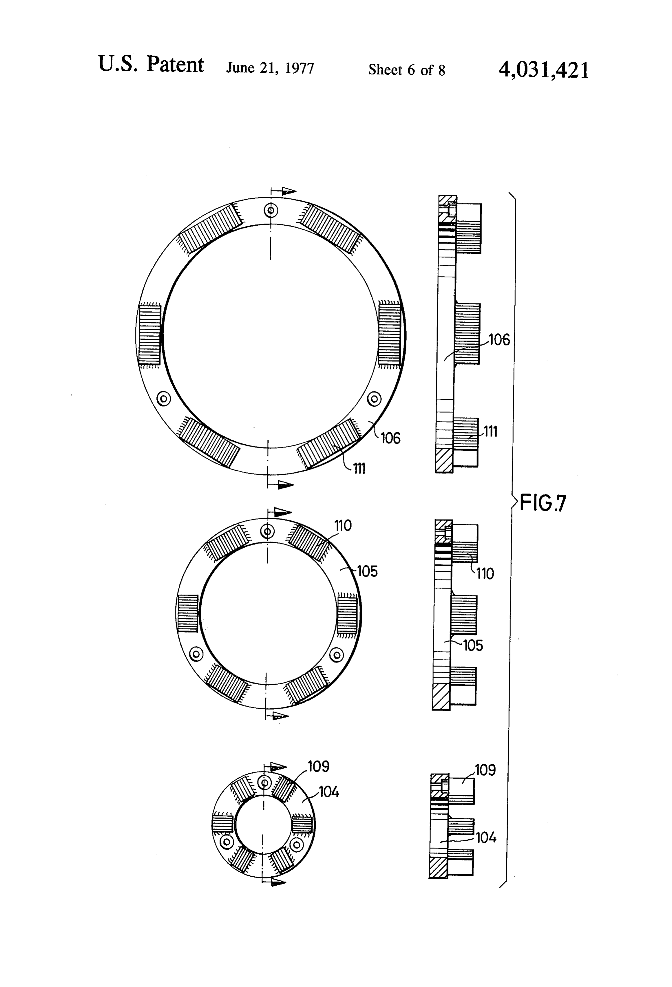
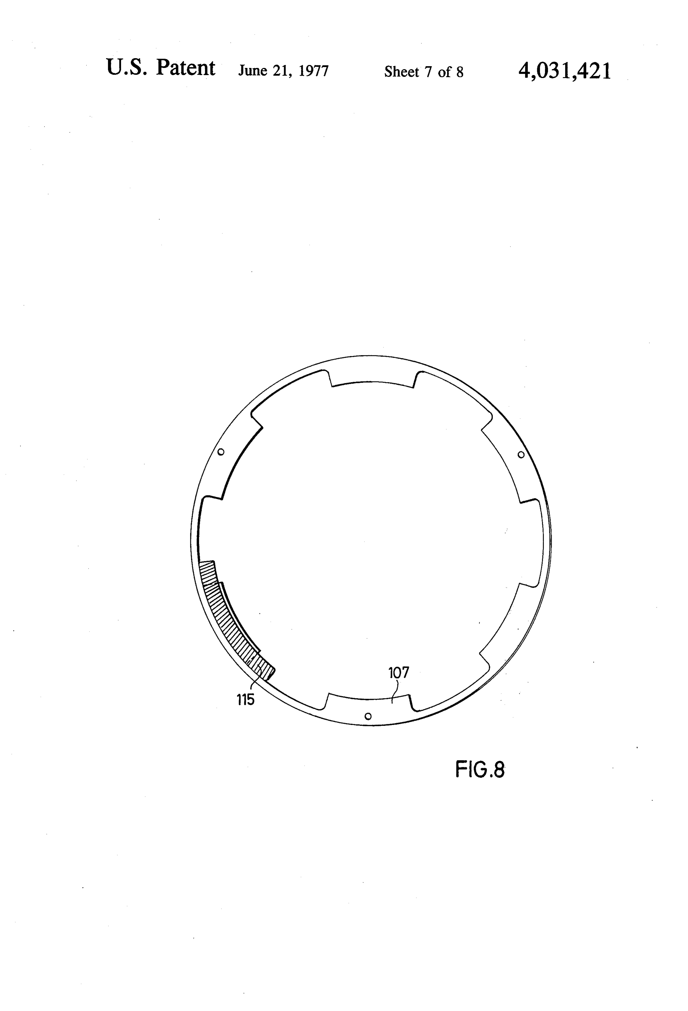
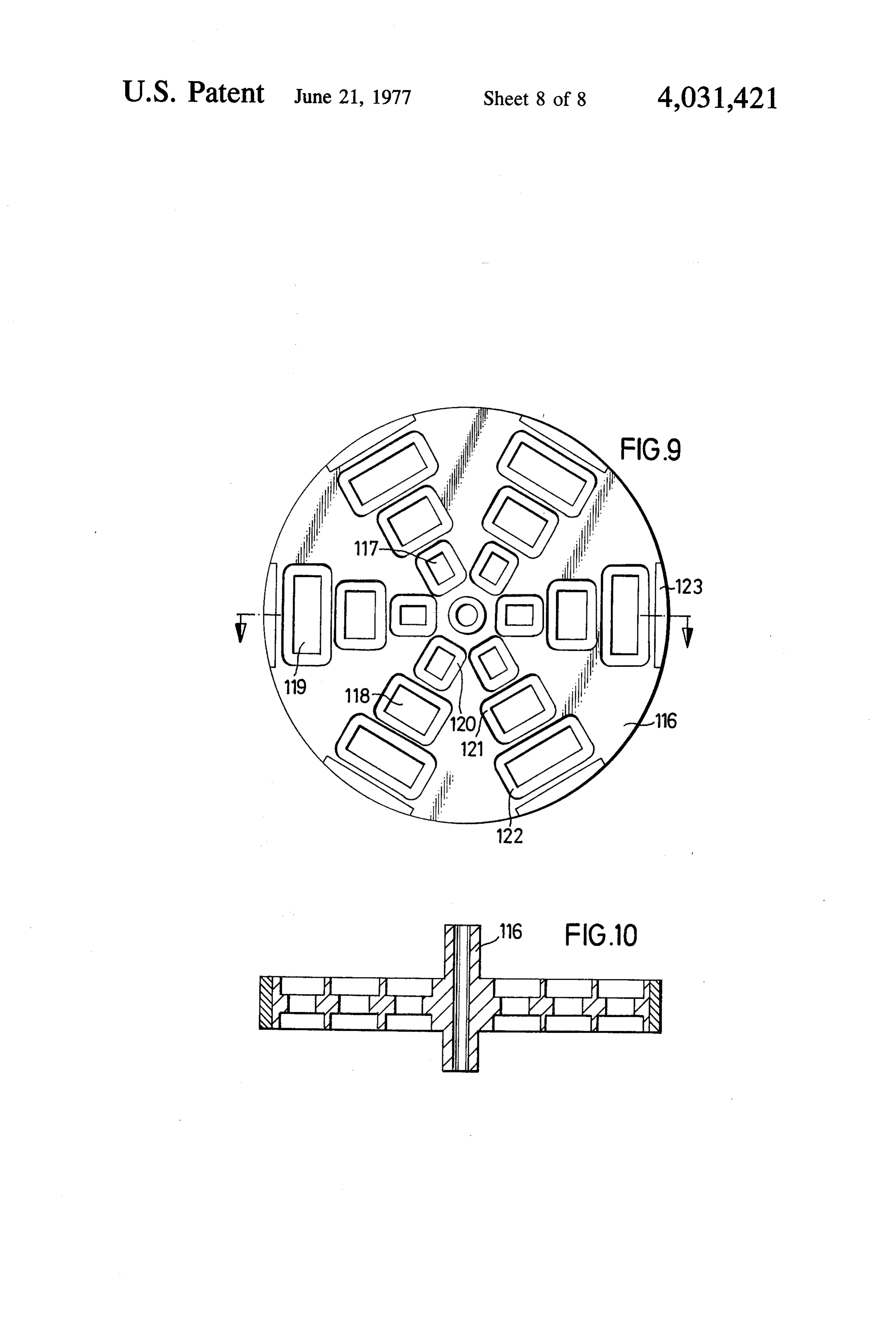
by using appropriate structural elements or units that FIG. 6 illustrates an axial, sectional cut-out (one side can be combined into various types and sizes of genera only) through another exemplary embodiment of the tors that have different outputs. inventive generator, portions thereof appearing in FIG. In accordance with major features of this invention, 30 7 in transversally take end and side views; the objects are attained in that rotors of at least a pair FIG. 7 is a combined detail view, both in front eleva of electrically identical but separate generator sections tion and from the side, of concentric yoke field rings of are mounted on a common shaft, the sections having FIG. 6;
pole cores that occupy the same sector areas as the FIG. 8 is an end view of a laminated yoke field ring gaps between them, and wherein the angular position 35 for radially directed stator poles; of the rotor shaft, in which the poles overlap between FIG. 9 is an elevation of a rotor according to FIGS. 6 the rotor and the stator in the same generator section, to 8; and is offset for both generator sections by half the angular FIG. 10 is a transversal, axial section through a main distance between the poles. body portion of the rotor.
Preferably the terminals or outputs of the two gener 40 The exemplary inventive generator shown in FIGS. 1 ator sections are so connected with a consumer or load to 5 has a very compact and simple construction, con that both sections are subject to about the same load. prising a central rotor shaft 5 having arranged thereon As a specific solution to this optional feature, a dou two groups of poles, namely radially disposed rotor ble transformer can be used between the generator poles 10a, 10b and stator poles 12a, 12b, and axially sections and the consumer. 45 arranged rotor poles 14a, 14b (for the spatial arrange In a further specific structural arrangement accord ment of the parts refer to FIG. 4). Further details will ing to the invention, the rotors of the two generator be given when describing the embodiment of FIGS. 6 to sections can be combined into a single rotor structure, 10.
carrying the poles of both sections, wherein preferably The respective lower and upper generator sections, the stator poles of the two sections are also offset by 50 as illustrated in FIGS. 2 and 3, are identified by numer half the earlier-mentioned angular distance between als 1a and 1b, also in FIGS. 4 and 5. The sections are the poles. coaxially disposed on the rotor shaft and surrounded by The generator sections preferably have at least one a common stator housing 3, the latter essentially in group of radially mounted, and another group of axially cluding a center portion 6 and two end shields 7a, 7b; mounted, pairs of the rotor and the stator poles. The 55 the latter can be pulled together, toward the center axially mounted poles are secured to both sides of the portion, by means of tie rods 8.
rotor. If the generator is constituted by several generator The axially mounted poles may form at least two sections and pairs, it is possible to provide more than concentric rings. This feature can be supplemented by one successive intermediate portion similar to 6. the similarly optional arrangement according to which 60 In the illustrated embodiment two rotors 18a, 18b are the stator poles, in at least one group of the pole pairs, rigidly connected with the shaft 5. The respective poles are disposed on at least two yoke field rings. 10a, 14a as well as 10b, 14b are in identical angular The invention also intends to cover stator poles that positions, as can be seen in FIGS. 2 to 5. have superconductive coils with a helium core, each In the development of planar rolling out of FIGS. 4, coil ring being provided with a separate helium inlet 65 5 the axially directed rotor poles, such as 14a, and also and outlet. the (not included) radial poles e.g. 10a assume posi According to a specific, preferred, exemplary em tions which correspond approximately to the maximum bodiment of the invention, the rotor can include at pull-down moment when the magnetic field breaks off 11 between these rotor poles of the generator section, and 18a, 18b of the first embodiment. In several concentric of the respective stator poles 12a, 16a, or in other groups the rotors are fitted with permanent or electro words to the condition of maximum field braking of the magnets having windings 120, 121 and 122 that are generator section 1a. axially oriented. On the outer peripheries the rotors The stator poles 12b, 16b of the other generator have radially oriented permanent magnets 123 that can section 1 b are offset by half a pole step or angular be applied, for example, by casting.
distance with respect to the stator poles 12a, 16a of the The rotors are surrounded by a common housing, first generator section 1a, the term "pole step' being including, as a matter of example, two lateral or end used herein interchangeably with the angular distance portions 101, 103 (7a, 7b) and one or possibly more between two poles that succeed one another in the O center portion(s) 102 (6). These elements are prefer peripheral direction (sometimes also called pole dis ably plate- or disk-shaped, with cylindrical cut-outs tance). (not shown) on their peripheries, allowing interengage In the position of the rotor shaft 5 shown in FIGS. 4, ment or overlap therebetween so that the generator 5 each rotor pole 10b, 14b of the rotor 18b gets closer presents a unitary and closed outer cover. to the respective stator poles 12b, 16b, and is in the 15 The end portions or covers 101, 103 carry separate illustrated position within a range in which approxi axial yoke field rings 104, 105 and 106 on their inner mately maximum attraction or magnetic moment ex surfaces that face the respective rotors, the rings having ists. The latter is opposed in its direction, related to the dynamo sheet bundles 109, 110, 111 applied thereto, rotation of the shaft 5, to the pull-down moment of the as shown, which latter elements are provided with re first generator section 1a, which also acts on the shaft 20 spective windings 112, 113, 114. 5 by way of the rotor 18a. The pull-down moment of Opposite the outer peripheries of the rotors 116, and each generator section equalizes or cancels out the particularly of the magnets 123, radially outwardly magnetic moment of the other. disposed lamination rings or bundles 107 can also be Practical tests have shown that the proposed arrange arranged on the covers 101, 123, which bundles carry ment of the inventive generator sections is capable of 25 windings 115, constituting yoke field rings. completely neutralizing the resulting field braking, The axially disposed yoke field rings 104 to 106 ap dispensing with (or actually saving) the rotational pear in FIG. 7 in front and side views, while FIG. 8 is an torque that was hitherto used to overcome this effect. end view of a radially disposed yoke field ring or bundle When using superconductive coils or windings agen 107.
erator can be constructed according to the inventive 30 In FIG. 6, the illustration is completed with conven principle that has an extraodinarily high efficiency. tional bearings 108 as well as cores or poles of interme As can be seen in FIGS. 4,5 the pole cores of winding diate members 117, 118 and 119, for the respective, supports require sectors identical with the gaps or in earlier-described windings 120, 121 and 122. terstices between the pole cores or supports. If perma Instead of the permanent magnets 123 on the rotors nent magnets are used as rotor poles, the same applies 35 116, a laminated bundle can be used (not shown) to the surfaces of the opposing poles on which the lines which can either serve as a short-circuited or a squirrel of force concentrate. This has as a result that the re cage rotor, or can have a winding thereon. spective pull-down moments of the generator sections The just described generator arrangement allows are at all times and in all angular positions of the shaft several stages or sections to be axially aligned. the fact 5 identical with the magnetic moments of the other 40 that all pole pairs, both the radial ones and those that sections, considering of course the described angular are axially oriented, have identical pole steps, uniform displacement of the generator sections. frequency conditions are obtained. In order to achieve the desired effect one must how FIG. 9 shows that the axially oriented pole pairs are ever ensure that the two electrically independent gen so grouped and spaced that in each yoke field ring erator sections are always subjected to the same load. 45 identical areas are used for the poles and for thier gaps. This can simply be achieved in that the sections 1a, 1b The arrangement including axially directed pole pairs feed the consumer or consumers through a (not illus results in a space-saving construction which yields con trated, conventional) double transformer and the like siderably high generator energy outputs. expedient. The mentioned simple and compact set-up allows It will be understood by those skilled in the art that in 50 standardized coils or windings to be made for all axially all figures, for ex. FIGS. 4 and 5, the letters N and S directed poles, which can be applied subsequently onto designate the known north and south poles while elec the lamination bundles that are embedded in the yoke trical connections or leads are designated by the inter field rings or placed on appropriate pole cores of the nationally accepted symbols R, S, T, U, V, W, X, Y, Z rotor, and which windings can eventually be intercon and O. The arrows in FIGS. 4, 5 designate the common 55 nected according to any desired electrical scheme, direction of rotation of the rotors 18a, 18b. depending on the particular electrical generator type. The second embodiment according to this invention, It should be understood, of course, that the foregoing shown in FIGS. 6 to 10, improves economy in such disclosure relates only to preferred, exemplary embodi generators, as will be explained, particularly by a spe ments of the invention, and that it is intended to cover cific, rather compact arrangement of the constituent 60 all changes and modifications of the examples de arts. scribed which do not constitute departures from the p FIG. 6 shows the left-hand half of an inventive gener spirit and scope of the invention.
ator with a lower and an upper rotor 116 (similar to the What I claim is:
sections 1a, 1b described so far), axially spaced apart 1. An electric generator comprising, in combination, with respect to a common rotor shaft 125 (similar to 65 a rotor with a shaft, a stator, both carrying respective, shaft 5; in the following similar bracketed numerals will peripherally successive poles with a substantially uni refer to the parts of the earlier-described embodiment). form angular distance therebetween, and at least one The rotors 116 can also be correlated with the units pair of electrically identical but separate axially aligned 12 generator sections, the latter including pole cores that 6. The generator as defined in claim 5, wherein said occupy substantially the same sectors as gaps therebe said axially mounted pole pairs are secured to both sides of rotor.
tween, and wheren the angular position of said shaft, in 7. The generator as defined in claim 5, wherein said which position said rotor poles overlap between the 5 axially mounted pole pairs form at least two concentric rotor and the stator of the same generator section, is rings.
offset from both generator sections by half the angular 8. The generator as defined in claim 7, further com distance between said rotor poles. prising at least two yoke field rings on which said axi 2. The generator as defined in claim 1, further com 10 ally9. mounted
The stator pole pairs are disposed.
generator as defined in claim 5, wherein said prising balancing means for connecting terminals of stator poles, in at least one of said groups of pole pairs, said generator sections in each pair to substantially the have thereon superconductive coils with a helium core. same consumer to avoid uneven loads therebetween. 10. The generator as defind in claim 5, wherein said 3. The generator as defined in claim 1, wherein said rotor includes at least two rotor sections mounted on said shaft, fitted on both sides with said axially mounted generator sections have separate rotor sections that are 15 pole combined on said shaft to constitute said rotor, the mounted pairs, and on their peripheries with said radially latter thus carrying said rotor poles of all sections. 11. The generator as defined in claim 10, further 4. The generator as defined in claim 3, wherein said comprising cover means constituted by at least two stator poles in said generator sections are also offset by 20 adjoining sections for carrying at least some of said half the angular distance between said poles. axially and said radially mounted pole pairs. 5. The generator as defined in claim 1, wherein said 12. The generator as defined in claim 11, wherein generator sections have at least one group of radially said cover sections have mating terminal portions for interengagement with such portions of neighboring mounted, and at least one group of axially mounted, 25 ones of said sections.
pairs of said poles in both said rotor and said stator.
Provenance
- Collection
- Patents citing this work
- Pages
- 12
- Method
- pdftotext (the PDF's own text layer) + pdftoppm 300dpi page scans
- Patent office record
- patents.google.com →
- Source
- Google Patents citing-documents table
- Assignee
- Gesig Energietechnik Gmbh
- Published
- 1977-06-21
- Transcribed from
- patentimages.storage.googleapis.com →