

patent · US4062346A
Solar collector unit
13 December 1977
Text
Page 1bibliographic recordscan →
United States Patent (19)
Rapp, Jr. et al.
(54). SOLAR COLLECTOR UNIT
(75) Inventors: Felix Rapp, Jr., Marlboro; James M.
Barron, Framingham, both of Mass.
73 Assignee: DIY-Sol, Inc., Marlboro, Mass.
(51) Int. Cl?................................................ F24, 3/02 52 U.S.C. .................................... 126/270; 237/1 A
2,213,894 9/1940 Barry .................................... 126/271 2,553,073 5/1951 Barnett ................................. 126/271 2,680,437 6/1954 Miller ................................... 126/270 3,254,643 7/1966 Thomason............................ 126/271 3,866,285 2/1975 Clark .................................... 126/271 3,902,474 9/1975 Pyle ..................................... 237/1 A 3,951,129 4/1976 Brantley, Jr. ........................ 126/271 3,961,619. 6/1976 Estes et al............................ 126/271
4,011,856 3/1977 Gallagher ............................ 126/271 Primary Examiner-John J. Camby
Assistant Examiner-Henry C. Yuen
Attorney, Agent, or Firm-Joseph S. landiorio
A solar collector unit including a corrugated absorber element coated with a reflectively selective coating; a plurality of thin, low mass, low thermal conductivity, thermal isolating elements for supporting the absorber element; and an insulation medium spaced from and generally parallel to the absorber element and disposed on a first side of the absorber element; a reflector sur face carried on said insulation medium between said first side and the medium; and an inner transparent insulating sheet spaced from and generally parallel to the absorber element disposed on the second side of the absorber element for transmitting solar radiation to the absorber element and suppressing heat loss.
8 Claims, 7 Drawing Figures
Drawings
Page 2drawing sheetscan →
Page 3drawing sheetscan →
Page 4scan →
collecting heated air from the absorber element. A sec
SOLAR COLLECTOR UNIT ond outer transparent insulating sheet may be provided FIELD OF INVENTION spaced from and generally parallel to the inner sheet and farther from the absorber element than the inner
This invention relates to a solar collector unit to a 5 sheet. The cold air input manifold may include a long, solar collector system formed of a plurality of said units. narrow input slot for producing a smooth laminar flow
Background of invention
along the inside of the inner transparent sheet and along the reflector surface to provide an insulating barrier
Current installed costs of most solar heating systems between the hotter turbulent air flow proximate the are quite high, often in the range of twenty to thirty-five O absorber element and the inner transparent sheet and dollars per square foot. The solar collector is typically reflector surface, and reducing transfer of heat between the most sophisticated part of such systems and requires that turbulent air flow and laminar flow. great care and skill in fabrication and installation to In a preferred embodiment a plurality of solar collec insure efficient operation. Often the materials and tech tor units are assembled to form a solar collector system niques used to construct solar collectors are quite ex 15 in which longitudinally abutting absorber elements are pensive and construction is best carried out at a special disposed with their corrugations staggered relative to fabrication site, rather than at the installation site. In each adjacent absorber element for promoting turbulent addition, some solar collectors tend to be large and air flow in the corrugations.
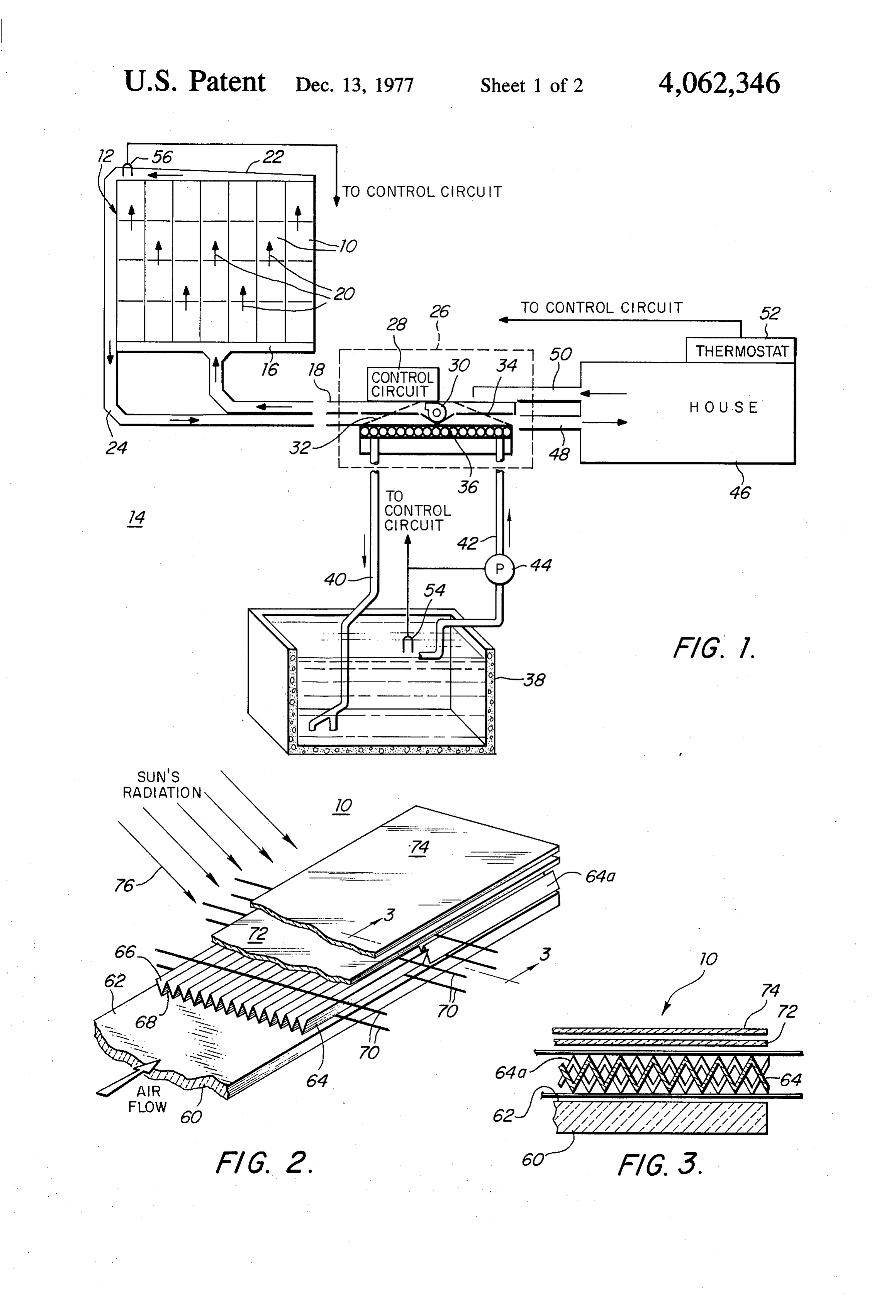
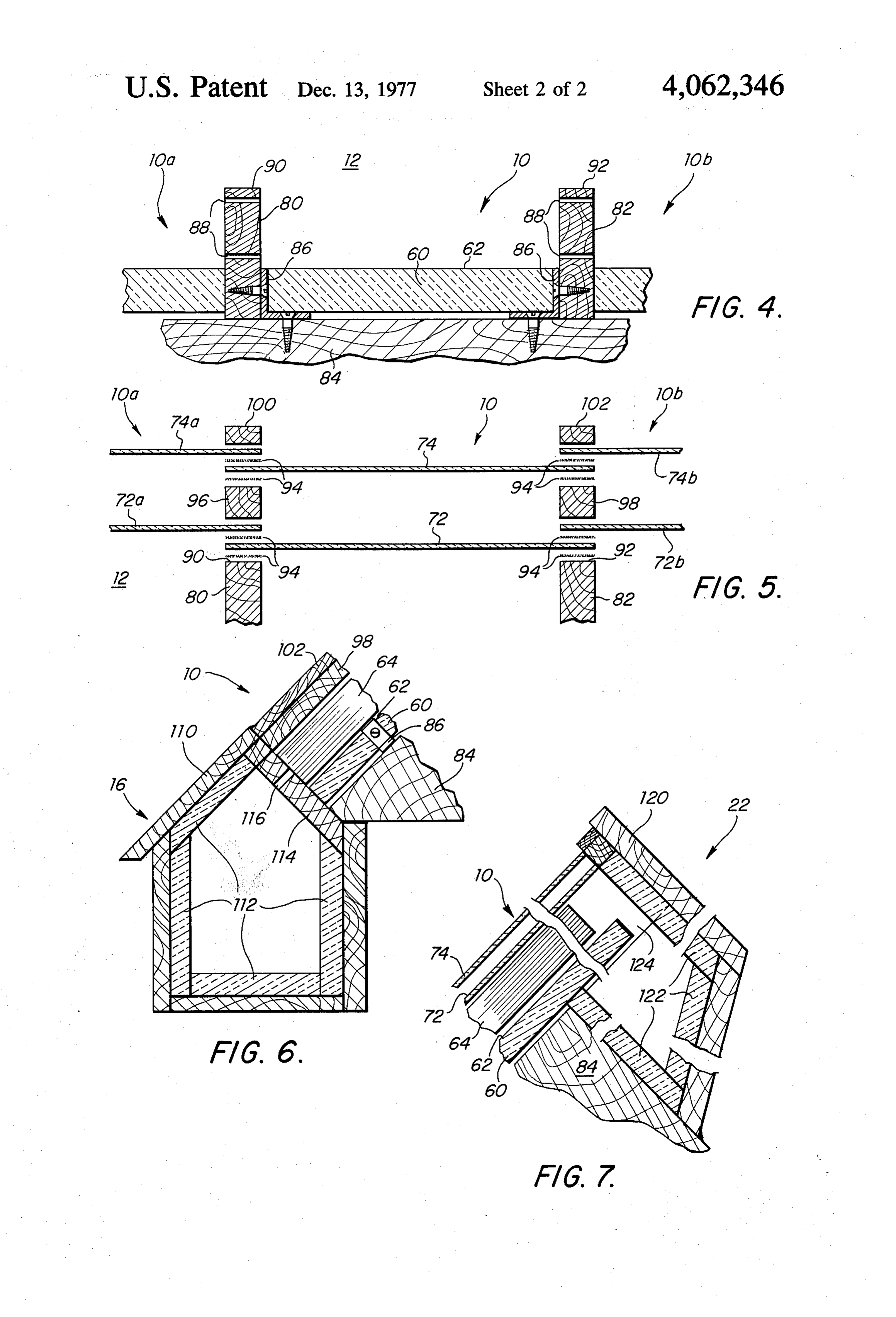
heavy, which makes them difficult to maneuver and Other objects, features and advantages will occur install and causes them to suffer from significant ther 20 from the following description of a preferred embodi mal lag: the delay of the collector in reaching a particu ment and the accompanying drawings, in which: lar temperature. There is a constant need for improving FIG. 1 is a schematic diagram of a solar heating sys heat transfer between the collector and heat-carrying tem which uses solar collector units according to this fluid and thermal insulation between the collector and invention;
the surrounding environment. 25 FIG. 2 is an enlarged detailed axonometric diagram SUMMARY OF INVENTION matic view of a portion of a solar collector unit accord ing to this invention;
It is therfore an object of this invention to provide an FIG. 3 is a cross-sectional view taken along lines 3-3 improved, simplified and relatively inexpensive solar of FIG. 2;
collector unit. 30 FIG. 4 is a schematic diagram similar to FIG. 3, It is a further object of this invention to provide such omitting all but the insulation and showing the side a unit which is simple and easy to install, which is less members;
than a third the cost of most present collectors, and FIG. 5 is a schematic diagram showing the mounting which can be constructed and installed by unskilled of inner and outer glazings on the side members of a persons using readily obtainable, inexpensive building 35 solar collector system which uses a plurality of solar supplies. collector units according to this invention; It is a further object of this invention to provide such FIG. 6 is a diagrammatic cross-sectional view of a a unit which has improved heat transfer from the ab cold air input manifold; and sorber element to the heat-carrying fluid and improved FIG. 7 is a cross-sectional diagram of a hot air output 'suppression of heat transfer from the collector to the 40 manifold. m surrounding environment. There is shown in FIG. 1 a plurality of solar collector It is a further object of this invention to provide such units 10 arranged to form a solar collector system 12 a unit which is extremely efficient and economical and forming a part of a solar heating system 14. Cold air which in a relatively small space, generally two hun manifold 16 fed by cold air duct 18 supplies cold air dred square feet of collector area, may provide approxi through the collector in the direction of arrows 20, mately forty percent of the space and hot water heating which is then collected by hot air manifold 22 which for a conventional house at 42° N latitude. feeds into duct 24.
The invention features a solar collector unit compris The solar heating system 14 also includes a control ing a corrugated absorber element with a reflectively unit 26 which includes a control circuit 28, blower 30, selective coating. There are thin, low mass, low thermal dampers 32, 34, and heat exchanger 36, which commu conductivity thermal isolating elements for supporting nicated with hot water storage tank 38 via input pipe 40, the absorber element, and an insulation medium is in a output pipe 42, and pump 44. Warm air is supplied to position spaced from and generally parallel to the ab house 46 to be heated via conduit 48, and cold air is sorber element on a first side of the absorber element. returned via conduit 50.
There is a reflector surface carried on the insulation 55 The temperature of the house is monitored by ther medium between the first side and the insulation me mostats2, that of the storage tank by sensor 54, and that dium. An inner transparent insulating sheet is spaced of the collector by sensor 56.
from and oriented generally parallel to the absorber In operation, air heated in solar collector system 12 is element on the second side of the absorber for transmit drawn from manifold 22 and duct 24 by blower 30, and ting solar radiation to the absorber element and Sup is directed into house 46 by means of dampers 32 and 34. pressing heat loss. When house 46 reaches a predetermined temperature In preferred constructions, the solar collector unit as indicated by thermostat 52, dampers 32 and 34 are includes a pair of side members disposed one along each manipulated to direct the heated air introduced through longitudinal edge of the absorber element for mounting duct 24 to heat exchanger 36. At this time pump 44 is the thermal isolation elements and the transparent insu 65 turned on so that water from storage tank 38 is directed lation sheet. There also may be included a cold air input up through pipe 42, through the heat exchanger where manifold for introducing cold air to be heated to the it is warmed, and then returned through pipe 40 to absorber element, and a warm air output manifold for storage tank 38. When due to cloudiness or sunset the 5 sun is not available and sensor 56 indicates that solar wires 70 which suspend absorber element 64. In a col collector system 2 is no longer providing heat at the lector system employing a number of collector units 10, desired temperature, a call for heat in house 46 by ther member 80 may perform as part of adjacent collector mostat 52 turns on blower 30 and pump 44 and arranges unit 10a as well as collector unit 10, and member 82 may dampers 32 and 34 so that cold air returned from the perform in the same way with respect to collector unit house is blown through heat exchanger 36, now being Ob, heated by warn water drawn from storage 38 by pump The top surface 90 of member 80 and top surface 92 44. The air is then returned through hot air duct 48 to of member 82 support inner glazing 72, as seen more heat the house 46. Solar collector unit 10 includes an clearly in FIG. 5, where inner glazing 72 is cemented to insulation layer 60 covered with a reflecting surface 62 O the top surfaces 90 and 92 by means of adhesive 94, such above which is suspended a corrugated absorber ele as a transfer film adhesive for "Tedlar' glazing. Inter ment 64 which contains selective coatings 66 and 68 on mediate straps 96 and 98 have been placed on top of each side. The corrugated absorber is suspended by inner glazing 72 after an additional layer of adhesive 94. thin, low mass, low thermal conductivity isolating ele Outer glazing 74 is supplied in the same manner, fin ments, 22ga. galvanized steel wires 70. Spaced above 15 ished off with cap straps 100 and 102, respectively. In absorber element 64 is an inner glazing 72 an typically collector systems having a number of laterally adjacent an outer glazing 74, which transmit the sun's rediation collector units such as shown in FIG. 5, laterally adja to absorber 64 but prevent heat transfer in the other cent inner glazngs 72a, 72b, may be overlapped and join direction. Insulation layer 60 and reflective surface 62 at the same point as inner glazing 72. This same con may be implemented by a rigid insulation such as Celo 20 struction is used for outer glazings 74a and 74b. tex “Technifoam TF 400', a rigid light-weight insula Cold air input manifold 16, FIG. 6, abuts the lower tion board with an isocyanurate foam core and reflec end of a solar collector unit 10 or a solar collector sys tive aluminum faces on both sides, which has a density tem including a group of such units, and includes a of about 1.9 pound/ft3and R factor of 9/inch. Absorber frame 110 whose interior is covered by insulation 112. element 64 may be a one and one quarter inch thick 25 The portion of the inerface panel 114 of frame 110 deeply corrugated, selectively coated aluminum foil which abuts the lower end of unit 10 includes an inlet whose absorptivity is 0.9 to 1.0 and emissivity is 0.2. slot 116 which is typically much narrower and not The absorptivity of the selectively coated aluminum foil wider than the corrugation depth of absorber element absorber element 64 is increased by multiple reflections 64. It typically has a gap width of approximately one within the corrugations. When the sunlight strikes one 30 eigth inch for each 3 feet of absorber element length. side of the corrugation to a greater extent than the Thus for collector system 12 as shown in FIG. 1, there other, the heat is conducted to the darker side, maintain are four three-foot absorber elements longitudinally ing a larger heat transfer area. Typically such sheets aligned; the gap would be approximately 4/8 or inch. come in sections, 2 feet by 3 feet, and weigh approxi Hot air manifold 22, FIG. 7, includes a frame 120 mately one pound. The selective coating 66 and 68 may 35 internally covered with insulation 122 and is provided be Alcoa 655. Inner glazing 72 may be Dupont "Te with an opening 124 communicating with the upper end dlar' 400 BG 20TR Poly Vinyl Flouride film of .004 of collector unit 10. In FIGS. 6 and 7 the manifolds and inch thickness, having a solar transmittance of 92% collector units are illustrated as being mounted on a from 0.4 to 3.0 microns. typical inclined roof of a conventional home. However, Outer glazing 74 may be the same material as the this is not a necessary limitation, as the apparatus may inner glazing 72 or may be Kalwall "Sun-Lite Pre be mounted entirely vertically or horizontally or any mium” Fiberglass reinforced plastic sheet of 0.040 inch other inclination with the geometry of the manifolds thickness having a solar transmittance of 85%. suitably rearranged to fit.
The solar collector system includes a plurality of The frame 120 of hot air output manifold 22 of frame solar collector units 10 in which longitudinally abutting 45 110 and cold air input manifold 16, as well as the side adjacent absorber elements are used. They are typically members 80 and 82, intermediate straps 96 and 98, and placed with their corrugations staggered relative to the cap straps 100 and 102 may be made of a good-quality adjacent absorber element to provide turbulent air flow wood such as Douglas fir without knots, finished clear in the corrugations and to prevent sliding one within the with three coats of polyurethane varnish to protect it. other of the successive corrugated elements placed 50 Other objects will occur to those skilled in the art and vertically or at a sufficient inclination to cause the upper are within the following claims. elements to shift, slide downward, and nest in corre What is claimed is:
sponding corrugations of the lower elements. This can 1. A solar collector unit comprising: be seen in FIG. 2, where like parts have been given like a corrugated foil absorber element of low thermal numbers and similar parts like numbers accompanied by 55 mass;
a lower case letter successively, beginning with a a reflectively selective coating on said absorber unit; There a second absorber element 64a constituting a a plurality of thin, low mass, low thermal conductiv second collector unit is shown with its corrugations ity, thermal isolating wire elements extending in a staggered with respect to those of absorber element 64. plane generally parallel to and beneath said ab This staggered arrangement is shown more clearly in sorber element for supporting said absorber ele FIG. 3, where the end view clearly shows the stagger ment;
ing of the corrugations of elements 64 and 64a, an insulation medium spaced from and generally par Preferably, insulation 60 and reflector surface 62 are allel to said absorber element, disposed on the bot mounted between side members or boards 80, 82, FIG. tom side of said absorber element; 4, which are fastened to the side or roof 84 of a conven 65 a reflector surface carried on said insulation medium tional home by means of brackets 86 and suitable fasten between said bottom side and said medium; and ing means such as screws or nails. Members 80 and 82 an inner transparent insulating sheet spaced from and have small holes 88 drilled in them to receive support generally parallel to said absorber element disposed 6 on the top side of said absorber for transmitting transfer of heat between that turbulent air flow and the solar radiation to said absorber element and sup laminar flow.
pressing heat loss. 7. A solar collector unit comprising: 2. The solar collector unit of claim 1, further includ 5 a plurality of solar collector units, each including: a corrugated foil absorber element of low thermal ing a pair of side members, one disposed along each mass;
longiudinal edge of said absorber element for mounting a reflectively selective coating on said absorber unit; said thermal isolation elements and said transparent a plurality of thin, low mass, low thermal conductiv insulation sheet. ity thermal isolating wire elements extending in a 3. The solar collector unit of claim 1 further including 10 plane generally parallel to and beneath said ab a cold air input manifold for introducing cool air to be sorber element for supporting said absorber ele heated to said absorber element longitudinally along ment; - an insulation medium spaced from and generally par both sides of said absorber element.
4. The solar collector unit of claim 1 further including 15 allel to said absorber element, disposed on the bot tom side of said absorber element;
a warm air output manifold for collecting heated air a reflector surface carried on said insulation medium from said absorber element. between said bottom side and said medium; and 5. The solar collector unit of claim 1 further including medium; and a second outer transparent insulating sheet spaced from an inner transperant insulating sheet spaced from and and generally parallel to said inner sheet and farther 20 gnerally parallel to said absorber element disposed from said absorber element. on the top side of said absorber for transmitting 6. The solar collection unit of claim 3 in which said solar radiation to said absorber element and sup manifold includes along narrow inlet slot for producing pressing heat loss.
8. The solar collector system of claim 7 in which a smooth laminar flow along the inside of said inner 25 longitudinally abutting adjacent absorber elements are transparent sheet and said reflector surface to provide disposed with their corrugations staggered relative to an insulating barrier between the hotter turbulent air each adjacent absorber element to promote turbulent air flow proximate said absorber element and the inner flow in the corrugations. k transparent sheet and reflector surface and improving
Provenance
- Collection
- Patents citing this work
- Pages
- 6
- Method
- pdftotext (the PDF's own text layer) + pdftoppm 300dpi page scans
- Patent office record
- patents.google.com →
- Source
- Google Patents citing-documents table
- Assignee
- Diy-Sol, Inc.
- Published
- 1977-12-13
- Transcribed from
- patentimages.storage.googleapis.com →